good thumb rule (at least in lower range of impedances) is to keep Rdc under 10% of impedance
 hard to make without core
hard to make without coregood thumb rule (at least in lower range of impedances) is to keep Rdc under 10% of impedance
Wow, R=6ohms seems to be not possible with an air choke, 20ohms is almost a limit. What will be a problem with Rdc=30ohms, only efficiency?
Wow, R=6ohms seems to be not possible with an air choke, 20ohms is almost a limit. What will be a problem with Rdc=30ohms, only efficiency?
yup ;
anyway - try it and decide do you like it
yup ;
anyway - try it and decide do you like it
No, better convert it to power amp by using a decent SE trafo. Although offtopic, could you advise requirements for buying Tango, Tamura or James ?
......could you advise requirements for buying Tango, Tamura or James ?
except in one occasion (pair of small Tamuras , from ancient Sony RtR) , I have no direct and broad experience with these ;
except in one occasion (pair of small Tamuras , from ancient Sony RtR) , I have no direct and broad experience with these ;
Other variants also good, Lundhall is not difficult to find out.
good thumb rule (at least in lower range of impedances) is to keep Rdc under 10% of impedance
Does the choke 1H, 450mA, 14ohms (the one from the enclosed table) fit this schematics? I hope its frequency responce is good. Manufacturer indicates it only for transformers. What more problems are possible?
Vladimirk, you might get some ideas on your shunt PS idea at the Borbely Audio website.
I think it is Home Page. He had developed some low and high current shunt regulators and I am using the high current one on my Phone pre-amp. Of course they are a bit more complicated but the schematics may give you some ideas. There was a recent article about them in Audio xpress a few years ago. Hope this helps-dave
I think it is Home Page. He had developed some low and high current shunt regulators and I am using the high current one on my Phone pre-amp. Of course they are a bit more complicated but the schematics may give you some ideas. There was a recent article about them in Audio xpress a few years ago. Hope this helps-dave
Vladimirk, you might get some ideas on your shunt PS idea at the Borbely Audio website.
I think it is Home Page. He had developed some low and high current shunt regulators and I am using the high current one on my Phone pre-amp. Of course they are a bit more complicated but the schematics may give you some ideas. There was a recent article about them in Audio xpress a few years ago. Hope this helps-dave
I still have not decided whether I shall really benefit from more complex shunt reg in this schematics. The PS filter with choke input (0,5 H, 2 ohms), plus I have added RC filtering stage (55ohms, 10000uF), gives less than 1 mV peak-to peak sine-like ripples before the shunt reg current source under rated load. Simple no-noise shunt reg must be enough to suppress the ripples down to 10uV (I can not see these ripples, as well as a noise, with my scope's resolution 1mV/10mm). And I am afraid of getting less dynamic responce from more complicated shunt reg schematics.
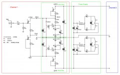
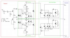
Here is schematics with the modified main power supply. I hope that due to the relatively high dynamic resistance of T5 and T6 current sources, the influence on sound of big c11-c14 electrolytics is suppressed. So, they could be an ordinary grade caps. The C1-C8 caps are still high grade ones.
Attachments
Yep, this one is more stable for draw and Leds more quiet than the first one. Still very simple, adheres to concept. Has no error loop correction with gain. Its a stabilizer, not a reg, and seems adequate for the draw and dynamics here. Could be subjectively very favorable.
Yep, this one is more stable for draw and Leds more quiet than the first one. Still very simple, adheres to concept. Has no error loop correction with gain. Its a stabilizer, not a reg, and seems adequate for the draw and dynamics here. Could be subjectively very favorable.
Thanks, Salas. I confirm, that Zener diodes must be prohibited in such schematics, with RED LEDs I see no even smallest traces of noise (scope's resolution 0,1mV/1mm). Hope to get this working (with 20k DACT input potentiometer) in 2-3 weeks (only some weekends are available for DIY). But, even with plain series PS, similar buffer (25mA current) with 10K ALPS input resistor sounds very detailed and authoritative with 50W Zen9. I like its sound so much that decided to repeat schematics with higher current and shunt stab.
You could replace the FET/LED shunt combo with a TL431, just a thought.
Possibly it will be useful to compare solution with TL431, but I am not sure that chip-based solution is better for sound.
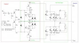
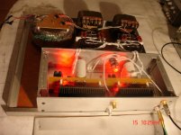
This Buffer Preamp With Shunt PS is almost ready, some case assembling is pending still. Enclosed is an As Built schematics. No electrolytics in the main part of schematics at all.
I shall post some scope screen photos. Speaking preliminarliy, I am able to observe some minor difference between the input and output signals only with 1 MHz square wave signal. No audiophile power cable is used at the moment, just something from scrap.
Sound is superior to both Parasound JC2 and the Buffer Preamp with Series PS. This is not my opinion, but of some relatives and friends. Combination of Current Source + Shunt PS is excellent thing. This solution "cuts out" from the game main supply electrolytics. I join the conclusion of Erno Borbeley and Are Waagbo (AudioXpress 2/08 p.30) in this aspect.
Attachments
Congratulations.🙂
Thanks, Salas. I think I should prepare good quality interconnect cables between signal generator - preamp - scope for taking correct screen shots. By the way, which preamp out load resistor you consider reasonable for measurements - 2k, 5k or 10k? Is where a standard value for it ?
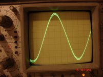
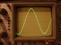
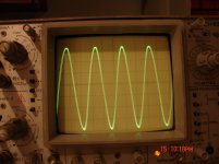
Enclose some scope shots, under 14V peak-to-peak sine signal, 5kOhm output load. First picture 1MHz signal, at maximum volume output is a bit lower than input. In the second picture I adjusted sensitivity of one channel of the scope for having equal amplitudes for both input and output signals. In this case the two signals become almost equal, phase shift of output is very small. The third picture is for 3MHz signal. Phase shift is visible now. It constitutes 1/30-th of a period, i.e. 1sec / (3000000*30) = 11ns. It is an extremely fast schemetics. Although, as we know, it has not too much importance for sound quality, but in this case we have it for free. Output noise is very low, I can not measure it by scope with 100uV/mm sensitivity.
Attachments
Last edited:
- Status
- Not open for further replies.
- Home
- Amplifiers
- Pass Labs
- Buffer Preamp with Shunt PS