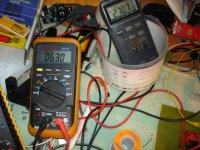
H/V Test with 30ma load
H/V fine.
From left AC input, V(R3), V(C9)(C8).
AC Input 261V
V(R3)=336VDC
V(C9)(C8)=269.3VDC
Load current=30mA
R1=22K, R2=100K
67V headroom for the regulator.
Run up time ~60min
Heatsink on IRF840 7.5C/W
IRF840 Temperature=46C
Room Temperature=27C
H/V fine.
From left AC input, V(R3), V(C9)(C8).
AC Input 261V
V(R3)=336VDC
V(C9)(C8)=269.3VDC
Load current=30mA
R1=22K, R2=100K
67V headroom for the regulator.
Run up time ~60min
Heatsink on IRF840 7.5C/W
IRF840 Temperature=46C
Room Temperature=27C
Attachments

Last edited:
Which particular ones? It looks correct to me? However i'm a noob 😛
Edit: C11 😉. I got ya.
Yep, it's C11 for sure.
Notice on this pic, the trace is on the other side, to what is shown on the board.
http://www.audiodesignguide.com/DACend2/Picture-077.jpg
Is this what you mean....
An externally hosted image should be here but it was not working when we last tested it.
So we just have to change the switch + sign to - right....!!!!
Anymore mistakes need to highlight here ?????
Is this what you mean....
An externally hosted image should be here but it was not working when we last tested it.
So we just have to change the switch + sign to - right....!!!!
Anymore mistakes need to highlight here ?????
No, only C11 needs to be rotated, then the board PASS. I mean this HV PSU board.
The other three need to be checked.
Last edited:
It looks like that the number 11 brings bad luck on H/V PSU board.
I can find 200R trimmer for the heater section. It seems that 220R is not popular.
With 200R trimmer and 9VAC input measured, output voltage cannot be adjusted below 7VDC then the heater bye bye.
I replaced R11 with 560R and you can obtain 6.3V near centre trimmer.
Heater DC output loaded with 1.38A
AC input 9.4V measured
Output 6.3VDC
Temperatures:
LM338 61C
R8 and R9 140C (mounted as Goalpost)
Bridge rectifier 80C
Transformer 33C
Picture shows PSU fully loaded.
Attachments
Last edited:
It looks like that the number 11 brings bad luck on H/V PSU board.
I can find 200R trimmer for the heater section. It seems that 220R is not popular.
With 200R trimmer and 9VAC input measured, output voltage cannot be adjusted below 7VDC then the heater bye bye.
I replaced R11 with 470R and you can obtain 6.3V near centre trimmer.
Heater DC output loaded with 1.38A
AC input 9.4V measured
Output 6.3VDC
Temperatures:
LM338 61C
R8 and R9 140C (mounted as Goalpost)
Bridge rectifier 80C
Picture shows PSU fully loaded.
hot! they are droping about 1.5v (ish) the reg has a pretty good sink on it, maybe better to let the reg burn off the heat. dont know without playing
Last edited:
hot! they are droping about 1.5v (ish) the reg has a pretty good sink on it, maybe better to let the reg burn off the heat. dont know without playing
You are right. 1.5V drop
The resistors are wirewound 4 watt and the current dissipation is 1W each.
The resistors are ok at that temperature but I want to avoid long term dry solder joints. The resistors are clear from the PCB about 5mm. Any suggestion?
I guess that's the way it is. The only thing to do is to reduce the resistor's value.
Last edited:
You are using the LM338 reg correct?
If the 317 was used (as labeled on the board) do you think this will make any substantial difference to the output voltage, still using 1k and a 200r trim?
Or even the LT1084 as described in the BOM. Also would this help drop the temperature of R8 and R9?
Sorry for the noob questions/ suggestions. 😱
they all have pretty much the same formula for setting Vout.
there was no beta phase for this so we are greatful to apelizzo for testing.
there was no beta phase for this so we are greatful to apelizzo for testing.
Cool, you're right. Thanks a lot to apelizzo, yes. I had just soldered my caps in yesterday (the wrong way around) so in maybe a weeks time there would have been a bang 😛. Saved now 🙂.
I'll throughly look over the boards again, see if i can spot any other errors.
Will changing the 1k resistor to a 560r modify anything else other than the range available for the trimmer?
It's just a little strange the way the silk screen has 200r on the trimmer, yet both the BOM's say 220r.
I'll throughly look over the boards again, see if i can spot any other errors.
Will changing the 1k resistor to a 560r modify anything else other than the range available for the trimmer?
It's just a little strange the way the silk screen has 200r on the trimmer, yet both the BOM's say 220r.
at some point, a blog point for all the part, orientation changes would be good. And I am glad someone like apelizzo is putting good due diligence ito bringing this beast up.
Anyone else getting close to finishing their's off?
As would really like to hear some feedback on this dac..
Might try it if it could end up better than my current gigawork cs4398 dac??
As would really like to hear some feedback on this dac..
Might try it if it could end up better than my current gigawork cs4398 dac??
You are using the LM338 reg correct?
If the 317 was used (as labeled on the board) do you think this will make any substantial difference to the output voltage, still using 1k and a 200r trim?
Or even the LT1084 as described in the BOM. Also would this help drop the temperature of R8 and R9?
Sorry for the noob questions/ suggestions. 😱
The LM338 replaced the LM317 because the LM317 (unless is LM317K) is rated only 1.5A so it was pulled to the limit.
As you see in my test for the LM338 I needed to run at least 9VAC input because the high dropout voltage of the LM338 . If you use LT1085 you may use slightly lower voltage. Or the other way around, if your AC voltage on full load is not at least 9V you must replace the LM338 with LT1085.
I had to replace R11 in my case. If I had 220R instead of 200 maybe was just enough to adjust to 6.3V. Not enough play anyway.
With regards to the bang, well.. it would happen after seconds, +/ 1 min. An inverted cap starts gassing and becomes hot very quickly.
Last edited:
I'm using the 1085, will report back on the trimmer once i get the transformer through. looking at the datasheet my guess is i will have to change r11 too.
Another Source for Elna
Another source
Elna Audio Grade Electrolytic Capacitors-ROA,ROB,RFS
Where can I buy Elna Silmic at good price?
Thanks for the parts list Apelizzo.
Another source
Elna Audio Grade Electrolytic Capacitors-ROA,ROB,RFS
No, only C11 needs to be rotated, then the board PASS. I mean this HV PSU board.
The other three need to be checked.
yes This PCb has a bug in the wrong.
You noticed I have marked a square hole or reject the + , alcohol is a circle hole welding -. What is difficult to mistake!
Thank you very much!
Thank apelizzo
Last edited:
Thanks Flocchini 🙂
*********************************************************
* ATTENTION
*
* The polarity of the C11 in the filament power supply pcb is wrong
*
*********************************************************
* ATTENTION
*
* The polarity of the C11 in the filament power supply pcb is wrong
*
*********************************************************
I've noticed a few change sin the BOM in the last week, especially for the power supply for the I/V.
Is it better to use this amended list now?
Have the changes been made been tested, also will it fix the voltage and temperature issues?
Also confirm that all diode's in the I/V PS are 1n4007 and 1n5062 has no place there.
What difference will there be also from 1n5062 to the 1n5819, in the salas shunt?
Last edited:
- Status
- Not open for further replies.
- Home
- More Vendors...
- Quanghao Audio Design
- OLD THREAD DAC End by Andrea Ciuffoli