I am plunging into an amp refurb head first. Ever since I was a young teen I wanted to build a Dynaco, Heathkit or other amp kit, but never got around to it. I got what I think is a good enough deal on this Eico HF-87 and have a copy of the kit assembly manual to work from. I’d like to hear opinions of how deep to go in terms of refurbing/rebuilding this amp.
I am confident that my assembly skills are just fine for the project. My deficiency is in circuitry know how and I am looking forward to learning the basics of tube amp circuitry in the process of this project. This will be learn by doing amp building 101 for me.
The amp works. There is hum at start up, but once warmed up the hum decreases significantly. The trim pots work smoothly and the amp gets very loud, so I am hoping the transformers are good. Apparently the surgistor is still working.
However, the sound is very very flabby, not tight and detailed at all.
The guy I bought it from says he is an amp tech and all he had done was the bare minimum to get sound out of it and try to reduce hum. He tried a few different tubes until he got the least hum, de-oxed the trim pots and re-soldered a few dry joints.
Looking under the hood, the actual build quality does not terrible, but there are still a number of suspicious looking joints. If it’s not really necessary to redo the whole works, I would be happy with a fully working amp with less than pretty build quality. But, I am wondering if I should just go ahead and rebuild pretty much down to new wire. It's not pretty in there but it's not horrible.
Here is a link to download a pdf of the manual complete with schematic and parts list:
Categorized Schematics and Service Manuals for free download
So, opinions please, should I gut the thing entirely and start anew, or work on replacing crucial parts piecemeal?
Also, does anyone know where I can get tubes tested in the Denver/Boulder Colorado area?
[images removed]
The 1st thing to do is look at the schematic, which I've uploaded. The signal topology is known as a Mullard circuit and we'll get back to that soon enough.
The 1st thing to tackle is the power supply (PSU). It is a matter of routine to replace all electrolytic filter caps. in the PSUs of "vintage" amps. 'Lytics literally dry out with time and flabby bass is the least of the trouble that they can cause. The HF-87 employs a Greinacher ("full wave") doubler PSU. Replace the 300 μF. doubler stack parts with 820 μF./250 WVDC parts from Jim McShane. Jim is a goldmine for parts and advice in restorations of this kind. The OEM diodes are noisy and should be replaced.
On the signal front, the 4X 0.1 μF./600 WVDC waxed paper coupling caps. should be replaced by electrically equivalent 716P series Aluminum foil and polypropylene film Orange Drops.
Contact Jim and you'll get all sorts of good hints for putting another quality vintage unit back to work doing what it should, playing music well.
Attachments
Thanks,
I just sent an email to Jim.
-Is there any reason to keep any of the old caps?
-Why change the value of the 300 μF to 820 μF?
-What type of diode is not noisy?
I just sent an email to Jim.
-Is there any reason to keep any of the old caps?
-Why change the value of the 300 μF to 820 μF?
-What type of diode is not noisy?
Last edited:
Thanks,
I just sent an email to Jim.
-Is there any reason to keep any of the old caps?
-Why change the value of the 300 μF to 820 μF?
-What type of diode is not noisy?
Hi Ben,
I got your email, I'll reply in detail.
But for the forum let me just say this amp responds very well to increasing the capacitance in the voltage doubler, that's why Eli made the suggestion.
There are some excellent diodes out there that are much less noist then the old types. I use some in my Citation rebuilds that work quite well, install easily and are inexpensive to boot!!
And no, the old caps all gotta go!
I'll get to your email in a few minutes.
Excellent, thanks. Now I need to start generating a list of parts to buy. Hereare the capacitors and rectifiers copied from the original parts list with recommendations (in blue) so far::
C1,2 elec 25mfd 6v
C3,4 molded .25mfd 400v
C5,6,7,8 molded .1mfd 600v 10% (Sprague orange drops)
C9, 10 elec 50mfd 50v
C11, 12 disc750 mmfd 1000v 10%
C13, 14 disc 225mmfd 10%
C15 elec 40-20mfd 500v
C16,17 elec, 300mfd 300v (Change to 820 mfd)
C18 molded .03mfd 600v
C19 elec 80mfd 500v
CR1,2 rectifier silicon 750ma 600PIV
Dude,
There are tweaks beyond improving the power supply. Jim and I will be delighted to discuss those, should you be interested. The fundamentals of the HF-87 are very sound, starting with a nice trafo set. That which is good to begin with can be improved on.
There are tweaks beyond improving the power supply. Jim and I will be delighted to discuss those, should you be interested. The fundamentals of the HF-87 are very sound, starting with a nice trafo set. That which is good to begin with can be improved on.
Has anyone got an extra output transformer for one of these? I bought one missing an OPT about 20 years ago and it has been sitting on the shelf ever since for want of an OPT.
Dude,
There are tweaks beyond improving the power supply. Jim and I will be delighted to discuss those, should you be interested. The fundamentals of the HF-87 are very sound, starting with a nice trafo set. That which is good to begin with can be improved on.
I've rebuilt a few of these and have another one sitting in the queue. Although it's a reasonably nice amp and the OPTs are impressively large... they're just not that great. Take a look at the original schematic and see what they did on the output stage to make up for a VERY unbalanced primary. Given the large difference in the DCR from side to side and the large cap across one of the halves, I might guess that the sectioning of the primary was minimal.
If the OP wants to keep close to the original circuit, then I'd suggest:
1. Power supply upgrade- bigger and better caps all the way around, replacement of the old diodes with high speed units (e.g., UF series), regulator for driver stage.
2. CCS to replace 18k tail resistor.
3. Matched plate resistors in phase splitter/driver stage.
4. Conversion to fixed bias- there's a handy-dandy extra winding (50V) on the power transformer for this- presumably, this was a feature in the prototypes, but was dropped for production.
4. Output tubes- EL34s work fine, EL37s work better (but are unobtanium), 7027/super 6BG6/6L6GC also work better (lower distortion, slightly more midrange power).
Thanks, I am considering tweaks discussed with Jim, and I think we are already doing several of these. Please let me know your thoughts:
1. Power supply upgrade- bigger and better caps all the way around, replacement of the old diodes with high speed units (e.g., UF series), regulator for driver stage.
Yes
C15 dual section JJ 100/100 500v
C16,17 560/400 clamp mount
C19 dual section JJ 100/100 uf 500 volt cap with both sections in parallel for a total of 200 uf
Also replacing all caps and improving values and types throughout
CR1,2 rectifier: 1000 PIV 3 amp UF5408 Vishay fast diode
2. CCS to replace 18k tail resistor.
I don't know what this means, please elaborate
3. Matched plate resistors in phase splitter/driver stage.
I believe you are referring to matching R28 for V5 and V7 on the other side (V4 and V6) correct? We are also changing value to 250 ohm for modern line voltage
We are also tossing the resistor connected from the EL34 to the 12ax7 heater and rewiring the 12ax7 heater from the regular heater supply. (I really don't get why they did that odd connection originally!)
4. Conversion to fixed bias- there's a handy-dandy extra winding (50V) on the power transformer for this- presumably, this was a feature in the prototypes, but was dropped for production.
Have not considered this yet. Please elaborate what needs to be done here... One practical problem here, Attaching to those leads will be difficult. They are cut quite short.
4. Output tubes- EL34s work fine, EL37s work better (but are unobtanium), 7027/super 6BG6/6L6GC also work better (lower distortion, slightly more midrange power).
I'll go with the EL34s for now. If I feel the need to change after listening for a good while, I'll consider this.
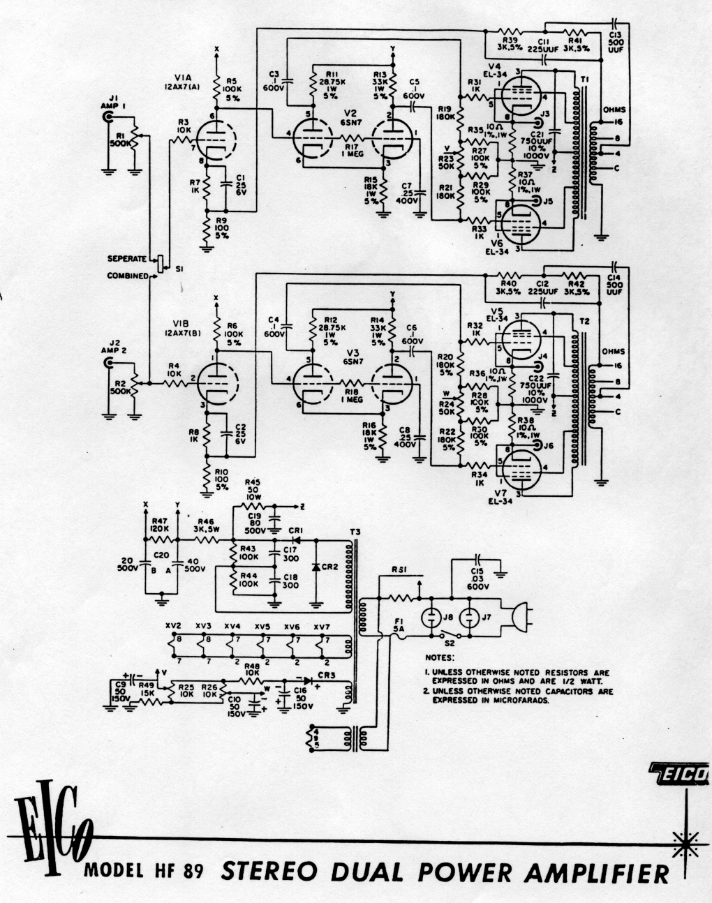
PLEASE PLEASE PLEASE, when referring to part numbers, use this schematic which is from the assembly manual I posted in the OP and matches the parts list I am working from. The part numbers differ from the schematic that Eli posted.
[image removed]
1. Power supply upgrade- bigger and better caps all the way around, replacement of the old diodes with high speed units (e.g., UF series), regulator for driver stage.
Yes
C15 dual section JJ 100/100 500v
C16,17 560/400 clamp mount
C19 dual section JJ 100/100 uf 500 volt cap with both sections in parallel for a total of 200 uf
Also replacing all caps and improving values and types throughout
CR1,2 rectifier: 1000 PIV 3 amp UF5408 Vishay fast diode
2. CCS to replace 18k tail resistor.
I don't know what this means, please elaborate
3. Matched plate resistors in phase splitter/driver stage.
I believe you are referring to matching R28 for V5 and V7 on the other side (V4 and V6) correct? We are also changing value to 250 ohm for modern line voltage
We are also tossing the resistor connected from the EL34 to the 12ax7 heater and rewiring the 12ax7 heater from the regular heater supply. (I really don't get why they did that odd connection originally!)
4. Conversion to fixed bias- there's a handy-dandy extra winding (50V) on the power transformer for this- presumably, this was a feature in the prototypes, but was dropped for production.
Have not considered this yet. Please elaborate what needs to be done here... One practical problem here, Attaching to those leads will be difficult. They are cut quite short.
4. Output tubes- EL34s work fine, EL37s work better (but are unobtanium), 7027/super 6BG6/6L6GC also work better (lower distortion, slightly more midrange power).
I'll go with the EL34s for now. If I feel the need to change after listening for a good while, I'll consider this.
PLEASE PLEASE PLEASE, when referring to part numbers, use this schematic which is from the assembly manual I posted in the OP and matches the parts list I am working from. The part numbers differ from the schematic that Eli posted.
[image removed]
Please disregard the CCS issue. I did a little research. At this time I do not wish to deal with a CCS mod... perhaps at a later date.
Answer to #3 is R13 and R15 (R14/R16) in your schematic.
The PT is somewhat marginal especially the 6.3V supply. That's why it powers the 12AX7 at the cathode of the output tubes. You can power it with a separate small transformer like it's bigger brother HF-89 which uses the same PT and a separate small transformer.
I did the fixed bias conversion to my HF-87 and is a good call. The lead is short but can be done carefully. The HF-89 is fixed bias and uses this -ve supply. If you do this mod, you will need a separate transformer for the 12AX7.
Answer to #3 is R13 and R15 (R14/R16) in your schematic.
my error; splitter stage... V2 and V3.
So what values and type should R13-R15 be replaced with?
The PT is somewhat marginal especially the 6.3V supply. That's why it powers the 12AX7 at the cathode of the output tubes. You can power it with a separate small transformer like it's bigger brother HF-89 which uses the same PT and a separate small transformer.
Understood. So by the following HF-89 schematic, all that is needed is a TF run off the line in? Easy enough. Is this a 12.6/12.6v or 6.3v/6.3v? I hope 12.6v; I already have several. Two show amperage ratings, one is 12.6/12.6 0.45 amps and the other 12/12 1 amp. Will these work OK?
I did the fixed bias conversion to my HF-87 and is a good call. The lead is short but can be done carefully. The HF-89 is fixed bias and uses this -ve supply. If you do this mod, you will need a separate transformer for the 12AX7.
OK, I am interested. Here is the parts list from the HF-89, Stick with these values or tweak?:
C9,10,16 electrolytic 50mf 150v
CR3 rectifier selenium 50ma
R48 10K 1/2W 10%
R23,24 pot 50K
R25,26 pot 10K
R49 15K 1/2W 10%
HF-89 schematic:
There is a Eico group at Yahoo Groups, and there has been quite a few discussion to the HF-87 as well as HF-89. Rather than repeating what others said and pretend I know more than I do 🙂 I suggest you to join the group. You will find quite a bit useful info there. For example, HF-87 and HF-87A have different OT's!!
Regarding to the 12AX7 transformer, I think the 12.6/0.45A is suffice. It only powers one tube.
In my case, I follow the HF-89 component values to create the fixed bias. Since the HF-87 and HF-89 have different OT's, I left the NFB network value untouched. I have neither a scope nor the knowledge to recalculate the NFB network. I have to admit I don't know how far off the optimal after converting t fixed bias.
Man, I hate listserve groups.
OK, easy enough to stick to the specified parts.
Back to #3 once again for anyone who knows (hopefully SY will follow up):
3. Matched plate resistors in phase splitter/driver stage.
I won't change these until I have a firm recommendation and explanation why to change values and what to change them to. What should R13-R15 be replaced with? And why were these pairs unmatched in the first place?
Last edited:
He is talking about R12 and R14. Do this only if you put a CCS in the tail of the phase splitter (R8/R10). The idea is that you buy a batch of 10 or so precision resistors and find two pairs that are the closest. The current design has them intentionally mismatched to make up for the fact that the tail in the LTP is just a simple resistor right now.
Morgan Jone talks about these different methods to make an LTP in his book. Improving this design will reduce distortion.
Morgan Jone talks about these different methods to make an LTP in his book. Improving this design will reduce distortion.
He is talking about R12 and R14. Do this only if you put a CCS in the tail of the phase splitter (R8/R10)... The current design has them intentionally mismatched to make up for the fact that the tail in the LTP is just a simple resistor right now.
Morgan Jone talks about these different methods to make an LTP in his book. Improving this design will reduce distortion.
Exactly. A tail CCS with matched plate resistors (30k or so) will greatly improve distortion performance. Cascoded DN2540 is two transistors and three resistors, not exactly rocket science. At cathode impedances, you probably don't even need to cascode, but it's so cheap and easy, may as well.
Thanks guys,
Can you point me to a schematic and parts list for a CCS addition? Like I said at the beginning, I do fine with hands on assembly and such, and learn through the process, but I lack circuit design know how. I don't learn well at all by reading, but do by seeing and working with things.
Can you point me to a schematic and parts list for a CCS addition? Like I said at the beginning, I do fine with hands on assembly and such, and learn through the process, but I lack circuit design know how. I don't learn well at all by reading, but do by seeing and working with things.
Wait a minute, I am really confused now. What schematic are you using? My schematic shows R12 as a 1 meg between grids of the two V3 triodes, and R14 coming off pin 5.
R13 and R15 are the plate resistors to be matched (30k nominal). I would also match the following grid leak resistors, R23 and R25. Their value can be anywhere from 120k (original) to about 270k, just make sure they're the same (and matched). Again, this is ONLY the case if you use the CCS in the tail- otherwise, the resistors need to be unbalanced as in the original, and the distortion performance will suffer.
The schamatic that Eli posted (Sams) had voltages on it. The 18k tail resistor has 125V across it. That means tail current is 125V/18,000 ohm = 7mA or so. So that's where you need to adjust the current source. There's a set resistor in the source of the "bottom" FET which will enable you to adjust the current. If you have an AudioXpress subscription (or access to back issues), I described how to do this in the Feb 09 issue.
I posted the DN2540 cascode current source a day or two ago. You should be able to find that with a quick search.
edit: Here's a link to the CCS circuit: http://www.diyaudio.com/forums/tubes-valves/156684-ccs-transistor-choices.html#post2033534
- Status
- Not open for further replies.
- Home
- Amplifiers
- Tubes / Valves
- Eico HF-87 refurb