Member
Joined 2002
I went with 3.3K bleeders for R1 and R2...tonight I hooked up the PSU to my xformer on the test bench in the C-C-C setup. It is a 200VA 12VAC toroid. I measured 17.2VDC on the PSU outputs.
I have placed an order for 10 .47ohm 3W resistors with some other misc stuff I needed...The voltage drop obviously will be negligible.
My HiFi2000 chassis shipped today so it should arrive in the next week or 2...cant wait to get it all assembled.
You will like the crc 🙂
Member
Joined 2002
HiFi2000..... You lucky dog!
Order one then 🙂
As soon as i start making a little bit of $$ ill be ordering 2 🙂
OK...I hooked everything up for a quick bench test...no inputs...
On both boards, only one of the mosfets(Q6) have voltage? normal?
Also, even the ones that have voltage are not warm at all...mounted temporarily on a sheet of aluminum...
Can someone give some guidance as to what voltages ought to be at particular critical points? I could probably stumble through but I'm sure someone has been here before...
Thanks in advance...
Member
Joined 2002
OK...I hooked everything up for a quick bench test...no inputs...
On both boards, only one of the mosfets(Q6) have voltage? normal?
Also, even the ones that have voltage are not warm at all...mounted temporarily on a sheet of aluminum...
Can someone give some guidance as to what voltages ought to be at particular critical points? I could probably stumble through but I'm sure someone has been here before...
Thanks in advance...
can you post pictures ?
Do you have all 3 power wires connected ? Positive negitive and gnd ?
jase
Yes...all power and earth ground connected from the wall to PSU board and to ch ground on the amp board.
Here are some voltage observations...
Q1: 9.2 -17.3 3.2
Q2: 0 -15.6 3.2
Q3: 13.2 3.2 16.35
Q4: -17.3 -17.3 -15.59
Q5: 17.1 17.2 17.2
Q6: -17.3 17.1 -15.6
Q7: 17.2 17.3 17.1
I hooked up an input and a small test speaker and there is no sound coming out...
I also took readings at all resistor terminals so I have those if it helps...
Carl
I dont think your source resistors are working,
What is the voltage across both sides of the resistors on Q6 and Q7, or r27 and r28.
So put volmeter positive on one side of the resistor, the other on the other side.
Should be ~.5v or 500mv.
What is the voltage across both sides of the resistors on Q6 and Q7, or r27 and r28.
So put volmeter positive on one side of the resistor, the other on the other side.
Should be ~.5v or 500mv.
Member
Joined 2002
Yes...all power and earth ground connected from the wall to PSU board and to ch ground on the amp board.
Here are some voltage observations...
Q1: 9.2 -17.3 3.2
Q2: 0 -15.6 3.2
Q3: 13.2 3.2 16.35
Q4: -17.3 -17.3 -15.59
Q5: 17.1 17.2 17.2
Q6: -17.3 17.1 -15.6
Q7: 17.2 17.3 17.1
I hooked up an input and a small test speaker and there is no sound coming out...
I also took readings at all resistor terminals so I have those if it helps...
Carl
Post pictures ? Don't forget to short the input side of the balanced to gnd.
R27: 17.29 / 17.29
R28: 17.06 / 17.06
I'll post pics later today...couldn't find my camera until late last night...
R28: 17.06 / 17.06
I'll post pics later today...couldn't find my camera until late last night...
***insert facepalm***
R13 - I ordered 47.5 ohm instead of 47.5k ohm...rookie...
who knows what else I fried as a result...
R13 - I ordered 47.5 ohm instead of 47.5k ohm...rookie...
who knows what else I fried as a result...
Member
Joined 2002
***insert facepalm***
R13 - I ordered 47.5 ohm instead of 47.5k ohm...rookie...
who knows what else I fried as a result...
Probably nothing 🙂
Make sure you short -in to gnd also if you are not using balanced 🙂
I just placed an order to mouser...I had to get some other items as well...I should be able to fire it back up Wed or Thu for some testing...
OK...getting very frustrated...still no voltage across the source resistors...fixed R13 with 47.5K and nothing...
No voltage across R1 D1 or the source resistors. How could I check Q1,2,and3? I don't know what to do next...
No voltage across R1 D1 or the source resistors. How could I check Q1,2,and3? I don't know what to do next...
I tried 2 more things last night...
1. finished adding the R to my PSU...3-0.47ohm resistors per rail (thought maybe the temporary jumper wasn't passing enough current???)
2. replaced the ZTX450's thinking maybe they got fried??? (unsure how to properly test though)
Still getting 17.4V per rail which is good...but why the @#$% is there no current passing through the source resistors and why is there no voltage across D1 and D2?????
Still getting about 17V at each leg of the source resistors to ground.
Once funny thing is that I am getting about 5V at D3...D5 is getting voltage...cant remember exactly but maybe it was 14 or so...
I even replaced the FET's with 2 spares I had not used just in case they blew the first time I fired it up.
This, I guess, is leading me to Q1,2,and 3...I do not know how to test them and by ruling almost everything else out leads me to believe that these may be the cause of my great frustration. Is there any simple DMM check I can perform on them for at least some type of rudimentary GO/NO GO without having to try and remove them??? I have a greenlee DM-20 that does have a diode setting.
Member
Joined 2002
I tried 2 more things last night...
1. finished adding the R to my PSU...3-0.47ohm resistors per rail (thought maybe the temporary jumper wasn't passing enough current???)
2. replaced the ZTX450's thinking maybe they got fried??? (unsure how to properly test though)
Still getting 17.4V per rail which is good...but why the @#$% is there no current passing through the source resistors and why is there no voltage across D1 and D2?????
Still getting about 17V at each leg of the source resistors to ground.
Once funny thing is that I am getting about 5V at D3...D5 is getting voltage...cant remember exactly but maybe it was 14 or so...
I even replaced the FET's with 2 spares I had not used just in case they blew the first time I fired it up.
This, I guess, is leading me to Q1,2,and 3...I do not know how to test them and by ruling almost everything else out leads me to believe that these may be the cause of my great frustration. Is there any simple DMM check I can perform on them for at least some type of rudimentary GO/NO GO without having to try and remove them??? I have a greenlee DM-20 that does have a diode setting.
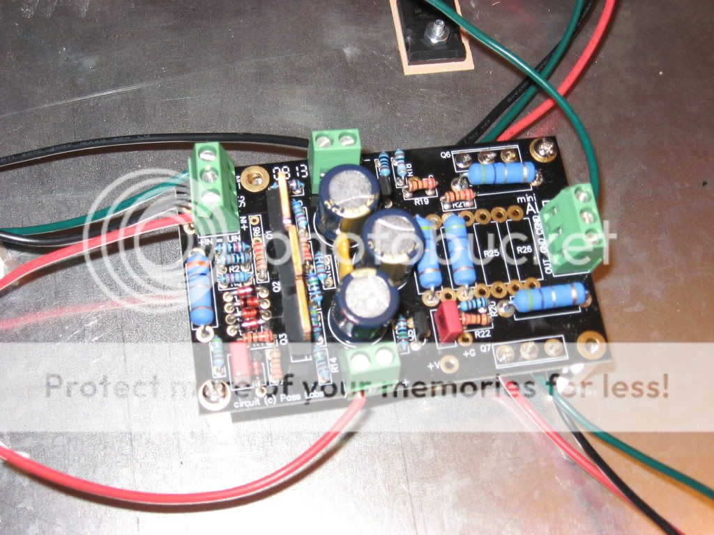
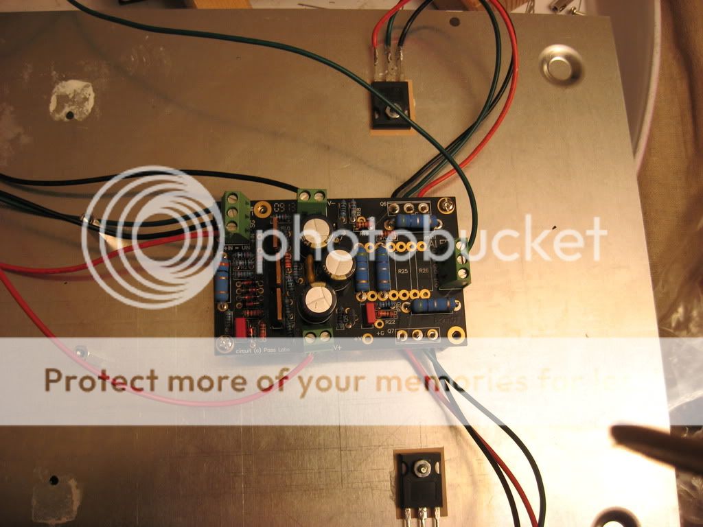
Post pictures please 🙂 take a hand full so i can see 🙂 i have a good eye 🙂
I'm about to throw in the towel...I cant take this anymore...I have checked and checked and checked...nothing makes sense and I'm about to pitch the whole thing...
This is the most frustrating project I have ever worked on....
This is the most frustrating project I have ever worked on....
Take a break and come back, clear mind sometimes helps.
Use the attach schematic to measure the voltage acoss the IRF9610's and the ZTX. Notice that the component names are different from Brian's board, but when you look at both schematic together, you can tell which is which. Hopefully, this will help you to isolate the trouble area.
Use the attach schematic to measure the voltage acoss the IRF9610's and the ZTX. Notice that the component names are different from Brian's board, but when you look at both schematic together, you can tell which is which. Hopefully, this will help you to isolate the trouble area.
Attachments
- Status
- Not open for further replies.
- Home
- Amplifiers
- Pass Labs
- New Aleph Mini PCB GB