My question is that whether this lower voltage have any adverse effect on the distortion figures of the follower. Listening tests didn't show any quality loss in output other than clipping at less volume.
Thanks.
Both lower supply voltage and lower SE class A idle current results in higher distortion.
Regards,
Hmmm...
So adding one more 1ohm resistor(~3A idle current) is a better idea for me. Probably it'll compensate a bit for the distortions due to lower voltage.
thanks.
So adding one more 1ohm resistor(~3A idle current) is a better idea for me. Probably it'll compensate a bit for the distortions due to lower voltage.
thanks.
Member
Joined 2009
Paid Member
Ahh, but there is no DC going through the inductor!
We must be talking cross purposes🙁
I'm simulating a CLC. The waveform after the rectifier diodes contains a good deal of dc with a good deal of ripple. The amount of ripple depends on the current drawn by the load and by the size of the first capacitor. When I look at the waveform after the inductor the ripple is smaller and the 'corners' are all rounded off. When I look at the FFT of the output compared with CRC there are fewer and smaller high frequency components.
All of the dc current flowing through the load, also flows through the inductor. There is a lot of dc going through the inductor.
The current through the L plus the current through the 2nd C is the load current, says Thevenin. Look at the difference in voltage level before the L and after. That was what I was trying to explain.
Can you post the sim curves for the current through the L?
jd
Last edited:
Member
Joined 2009
Paid Member
I don't pay much attention to Thevenin, he's not gonna build my amp for me 😀
I don't have my sims to hand, will try to post later...
I don't have my sims to hand, will try to post later...
Member
Joined 2009
Paid Member
I had a quick look again at the sims. It's going to depend on what I put in as to what I get out. The ideal inductor has no internal resistance and I see a smooth output voltage with enough inductance. To get the same ripple level with CRC I have to use a lot of R and the voltage is clearly much lower. But if I accept more ripple from the CRC option and include internal resistance to the inductor then I can obtain the same drop out voltage in both cases. So I'm not sure which plot would be useful.
Try to remove the first cap, get LC, and analyze under a nominal load.
With no load you would not see any differences.
Now, add first C in CLC and play with it's capacitance. Do you see any differences in output voltage?
Got it?
With no load you would not see any differences.
Now, add first C in CLC and play with it's capacitance. Do you see any differences in output voltage?
Got it?
Member
Joined 2009
Paid Member
I'm a bad student....I should be understanding the issue here much more quickly.
With an LC instead CLC the output is very different, nasty voltage droop and lots of ripple. The current pulses through the diodes are now quite different because they see a markedly different load without that first capacitor.
I introduce a first capacitor that is small and I see no difference. As I increase the size of the first capacitor it makes a more noticeable contribution to the impedance seen by the diodes. Make this first capacitor large enough and the voltage at the output increases significantly over that of the pure LC. I do see how the inductor made for a lower voltage output if you don't have the capacitor in there.
What I objected to originally was the statement: "CLC's do sacrifice substantial voltage compared to a straight C supply.", So I tried simulating CLC verses CC (where total capacitance and load is the same in both cases), the voltage from the CLC sits at the lowest of the range of ripple oscillations from the CC version. The average voltage of the CLC is therefore lower, but as it has no ripple (or at least very little), the usable voltage of the two options is the same ??
Last edited:
In CLC you may vary first C to decrease output voltage, and to decrease current peaks on rectifier.
Hello Dear Experts.
It looks like the topic you are talking about is quite interesting and I think it deserves a thread of its own. That way there might be more elaborate and uninterrupted discussion on the matter of CLCs etc.
Thanks for your cooperation.
It looks like the topic you are talking about is quite interesting and I think it deserves a thread of its own. That way there might be more elaborate and uninterrupted discussion on the matter of CLCs etc.
Thanks for your cooperation.
Hello Dear Experts.
It looks like the topic you are talking about is quite interesting and I think it deserves a thread of its own. That way there might be more elaborate and uninterrupted discussion on the matter of CLCs etc.
Thanks for your cooperation.
Dear Shaan;
back to the follower, everything depends on your load resistance, and how much power do you (and your MOSFETs+heatsinks) agree to dissipate.
Say, you have 8 Ohm load, and can't tolerate more than 100W on both transistors (or they can't tolerate more).
The current source have to provide current no less than peak current on your load (speaker). If it's impedance is 8 Ohm, 50W dissipation means idle current no less than square root from 50/8. Now, you can calculate a voltage of the supply dividing 100W on idle current.
Got it?
In CLC you may vary first C to decrease output voltage, and to decrease current peaks on rectifier.
Are you saying that the charging cycles for the caps cause the diodes to increase voltage drop?
It does at high currents, but at the end of the charge cycle it decreases again because of the lower currents (same with input AC ESR). Also, heating them up will decrease voltage drop; so it's possible that intense charging cycles will actually decrease voltage drop.
I can see how CLC without the first C could be better. The first C takes all the charging cycles, and these high current peaks might pollute grounding.
But at the same time, the faster charging cycles through the L might create magnetic interference.
LC will also charge slower than CLC because the L's see pulse instead of pure DC, and so they can't settle to a DC current value that will charge the caps gradually. So some of the input voltage never makes it to the output at startup, because the pulse turns off before the inductor can establish a DC current.
- keantoken
Are you saying that the charging cycles for the caps cause the diodes to increase voltage drop?
No, I am not so ignorant. I can show you my MS EE Diploma. 😀
I am saying that the higher are ripples on input, the lower is an average voltage on output.
Got it?
Okay, so you seem to be saying that an input with higher ripple will take more of a hit from load current; this is because the supply can only dump a limited amount of current into the caps between the times they are discharged by the load - only DC loading can decrease output via ESR (I almost forgot to compute load current).
On an arbitrary note, it seems that the most power efficient passive CLC supply will have minimal DC current through the inductor, but will never have the inductor turning completely off either. (so the inductive impedance is no more than necessary)
This brings some questions up in my mind whether it would be better use of resources when considering universal ESR, to separate into multiple LC stages, each tackling its own aspect of the work.
Sorry if I inadvertently seem to insult your intelligence on occasion; when language is vague to me I probe details instead of doing the social "plausible assumption" thing.
- keantoken
Dear Shaan;
back to the follower, everything depends on your load resistance, and how much power do you (and your MOSFETs+heatsinks) agree to dissipate.
Say, you have 8 Ohm load, and can't tolerate more than 100W on both transistors (or they can't tolerate more).
The current source have to provide current no less than peak current on your load (speaker). If it's impedance is 8 Ohm, 50W dissipation means idle current no less than square root from 50/8. Now, you can calculate a voltage of the supply dividing 100W on idle current.
Got it?
The follower's idle current is 2.25A. Max voltage is 40V. Dissipation should be 90Watts(45w per device, DoZ pre used to divide voltage into halves at output.). Looks like it is 90watts. The small heatsink needs a fan to remain touchable. Load impedance indeed is 8ohm. So I think I got it. Please don't ask me to go deeper coz I am not in the mood and ain't so bright. 😀
But the follower didn't ever have a problem with dissipation and still doesn't. I know how to calculate max idle current based on load R. I have no problem with that part of the theory, and unlike the oscillation problem it really reflected into the real world too. Lower supply causes earlier clip; not some problem.
thanks for your concern.
Last edited:
Shaan,
I don't think you need worry about not being too 'bright', this ain't rocket science, and it's easy to ramp it up into something involving higher maths, which you don't need here at all... P = IV just about sums it up, after all.
If the mosfet itself is not touchable, it means case temperature is over 65C. At this temperature, MTBF is much reduced, roughly halving with each 10C rise over 20C. I try not to run them at more than about 37 watts, at which temp they will last about fifteen years in my experience. You might consider doubling up on mosfets to spread the load, in fact. Distortion will be slightly higher, but it will be more reliable.
Wavebourn,
KeanT is not challenging you; he's just a young guy, and a very bright one. Your experience outstrips most of us, me included.
Nice circuit, that gyrator. Still trying to figure it all out.
And I still really like your workspace. I'm not showing you mine, it's actually much worse......
Hugh
Last edited:
Okay, so you seem to be saying that an input with higher ripple will take more of a hit from load current; this is because the supply can only dump a limited amount of current into the caps between the times they are discharged by the load - only DC loading can decrease output via ESR (I almost forgot to compute load current).
Not exactly. Jan Didden and myself, we were talking about averaging of a voltage by LC filter. Just draw a waveform of rectified sine wave, and without any math/integrals try to imagine an average voltage after the filter. Now, add some capacitor turning LC filter in CLC filter. It will be charged by peaks of a rectified sine wave, then discharge by load, so there will be some DC + ripples: the lower capacitance, the deeper ripples. The higher is the capacitance of the 1'st capacitor, the higher will be an average voltage. The max will be equal to amplitude of peaks. It is the whole point. No black magic.
We were talking about much simpler thing than you are trying to discuss.
This brings some questions up in my mind whether it would be better use of resources when considering universal ESR, to separate into multiple LC stages, each tackling its own aspect of the work.
I have the same question 🙂
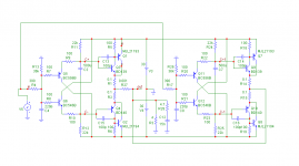
If you guys wanted to play with much more powerful toy, than go for this. Again a follower, now push-pull, class A. Set overall idle about 1.5A. Idle is set by R11, R12, R24, R25.
The photo is here, on the left -
http://www.diyaudio.com/forums/soli...ollower-no-darlington-mod-26.html#post2064444
Have fun,
The photo is here, on the left -
http://www.diyaudio.com/forums/soli...ollower-no-darlington-mod-26.html#post2064444
Have fun,
Attachments
Member
Joined 2009
Paid Member
The Diamond output Looks quite similar to my "Bigun's Botch Up" amplifier version 3
I'm enjoying this foray into Class A 😀
I'm enjoying this foray into Class A 😀
Last edited:
- Status
- Not open for further replies.
- Home
- Amplifiers
- Solid State
- Pavel's MOSFET Follower - No Darlington Mod