Well that is what decoupling is. But it is true that NP has expressed strong opinions against decoupling on the F5.
I would assume that this is highly dependent on the actual implementation, but since decoupling can give you better high frequency performance at best, I think it is very much irrelevant for this amp, unless you as jack use it in the ham bands.
My comment was aimed at those who place supply film
caps right on the channel board. I can make an F5
oscillate doing that, so I think you will want to have a
scope to evaluate the results if you play with this.
😎
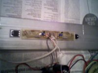
hi.I built an F5 for trying.I didnt use ztx transistors and thermistor for now.DC offset is 1v when bias is near zero and when i am turning the pots I see 0.7 volts on 0.47r resistors and the offset is 700mv.. the 0.47 resistors are getting too hot when i am trying to lower the offset.I connected it to speaker and played music.It works but not properly I think.Did i burned the p channel mosfet?.Does it play with one mosfet ?What can i do ?
Attachments
You have to adjust it to get <10mV offset. Select one 0.47 to be the reference and set that to .59V and close to zero offset. And you don't have to worry about the exact value of the other 0.47 resistor. Let it heat up and do the adjustment again.
No it won't play nice music with one fet burned!
No it won't play nice music with one fet burned!
I remember that it was playing music with only one transistor but not nice about a year before 🙂 I hope nothing burns
You have to adjust it to get <10mV offset. Select one 0.47 to be the reference and set that to .59V and close to zero offset. And you don't have to worry about the exact value of the other 0.47 resistor. Let it heat up and do the adjustment again.
No it won't play nice music with one fet burned!
now i measured the dc supply and saw that it is +-21.5 volts.Here it is snowing cats and dogs and there are electricity outage at somewhere in my country.Maybe this is the reason of low voltage.what is the min supply of F5?I am not sure.
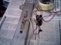
This is the quietest F5 I have built -- 23uV 22Hz - 22kHz -- the transformer is mounted on the front panel and its leads tightly twisted and clamped to the bottom of the chassis. I used 3 lead shielded mike cable with the shield tacked to the chassis. The input and output cables are at right angles to the power cable. The capacitor bank is hard-wired on a piece of FiberGlas but I used some 3M tinned copper tape on the bottom.
The black handles are Chinese imports from Home Depot!
An externally hosted image should be here but it was not working when we last tested it.
The black handles are Chinese imports from Home Depot!
my f5 under load is around 20 V. Whithout load is about 22V ... trasformer is 17V AC.
I think that it is risky to remove the protection circuit ....
I think that it is risky to remove the protection circuit ....
my f5 under load is around 20 V. Whithout load is about 22V ... trasformer is 17V AC.
I think that it is risky to remove the protection circuit ....
Is your circuit original?Does it work well at this voltage?
my amp is biased about 1.2 A (0,57V on resistors due small heatsinks). Transformer 600VA . Output devices Vishay IRFP. Sound is excellent IMHO.
I do not know why my offset is 900mv
That is because you have not properly adjusted the amp. Read my instructions and those in the manual: http://www.firstwatt.com/downloads/F5-om_sm-080527.pdf
It is just like adjusting the water temperature on a old fashion two knob water faucet.
I know and read this instruction.I built F5 amp successfully a year ago but i do not know why it doesnt work properly now.🙁
Ok, I'll repeat myself.
To adjust the F5 is a balancing game. You should NOT aim for equal voltage over the two 0.47, but just to have one showing .6V and zero dc on output. So if you have a positive dc voltage, you need to reduce the resistance over P1 so the current through R11 drops and your dc goes down.
To adjust the F5 is a balancing game. You should NOT aim for equal voltage over the two 0.47, but just to have one showing .6V and zero dc on output. So if you have a positive dc voltage, you need to reduce the resistance over P1 so the current through R11 drops and your dc goes down.
I usually try to start adjustment at 200mv, then 400mv after 10 or so minutes, not trying to reach ~0v offset until .590 or so volts. Usually around 50mv offset to start.
The bias is getting too high when i try to adjust dc offset to zero
How about adjust the other bias-pot instead, fore final dc-offset, and bias should go down a bit instead, right ?
It is just like adjusting the water temperature on a old fashion two knob water faucet.
Exactly!
How about adjust the other pot instead
Indeed.
Last edited:
How about adjust the other bias-pot instead, fore final dc-offset, and bias should go down a bit instead, right ?
I try everything but nothing changes.I see 4.8 volts on R3 and 3.8volts on R4.I will put out these components and replace another ones
I try everything but nothing changes.I see 4.8 volts on R3 and 3.8volts on R4.I will put out these components and replace another ones
Just as I suspected. 😉
- Home
- Amplifiers
- Pass Labs
- F5 power amplifier