IIRC, Hfe linearity improves with higher Vce, and there is also Early affect. This parameter would be Vaf in the model.
- keantoken
keantoken
you say linearity improves, but, would the Hfe increase with higher Vce?
I am not sure. I'm leaning towards no, unless the transistor is near CB saturation.
I'm not sure how Early affect plays here (Ic increases with Vce).
It might even be different for different transistors.
(in short, I shouldn't have tried to answer - sorry)
- keantoken
I'm not sure how Early affect plays here (Ic increases with Vce).
It might even be different for different transistors.
(in short, I shouldn't have tried to answer - sorry)
- keantoken
keantoken,
hey, if you don't try, you don't learn... just thinking about these things helps;
Bob Cordell gave an answer in the Spice Simulation thread
http://www.diyaudio.com/forums/software-tools/101810-spice-simulation-new-post.html
Ken
hey, if you don't try, you don't learn... just thinking about these things helps;
Bob Cordell gave an answer in the Spice Simulation thread
http://www.diyaudio.com/forums/software-tools/101810-spice-simulation-new-post.html
Ken
I looked at Andy_s's models for the mjl3281 and the BF= 438 and mjl1302 BF=122. Very different, seems like the N device will be doing the heavy current lifting...
Ken L
Ken L
Interesting, the answers and ensuing discussion bring up more questions.
In the Allison, both output transistors share current equally, so really it's only the drivers you need to worry about. (same for a darlington EF as long as you have low enough impedance base drive, as Ic then depends more on Vbe than on Ib)
- keantoken
In the Allison, both output transistors share current equally, so really it's only the drivers you need to worry about. (same for a darlington EF as long as you have low enough impedance base drive, as Ic then depends more on Vbe than on Ib)
- keantoken
Interesting, the answers and ensuing discussion bring up more questions.
In the Allison, both output transistors share current equally, so really it's only the drivers you need to worry about. (same for a darlington EF as long as you have low enough impedance base drive, as Ic then depends more on Vbe than on Ib)
- keantoken
yeah, but, the outputs are multiplying current as well as the drivers yes?
Maybe you should look at this from a transconductance point of view. A transconductance amplifier takes a certain input voltage and turns it into output current.
A transistor is just that. You might even say that Ib is a parasitic property. (nevermind the odd coincidence that it is roughly a factor of Ic)
You could use current drive on the base (like driving it with a modulated CCS), but that's less reliable - transconductance (Gm) is constant among transistors, Bf is not.
Where Ib fits in is that if you plan on making a change in Vbe you must accept that you have to drive Ib as well. This strongly affects OLG in an amp. Think of an electrometer. It takes no current, just give it some voltage and it'll do work. Not much different from a MOSFET. An electrometer won't even tickle most circuits. Setting aside EMI and capacitance, it would be a joke to design a HI-FI, wire-with-gain amp if what you were driving was an electrometer.
But since in a BJT Ib is roughly proportional to Vbe, it's more or less a nonlinear resistor as seen by what's driving it. This loading decreases gain. (obviously, of course. I must be rambling)
Maybe I misunderstood you. Are you just saying that the lower Bf device will take more of a beating because of the increased Ib? Principally, it is different, but AFAIK there's no more or less power going through the transistor than there would be on the higher gain device. It's the transistor that comes before that (driver) that I'm worried about, since a low Bf tends to add up once you factor in high-current gain rolloff.
Pardon me if I'm making a little less sense in the way I'm responding. Christmas break is over and I could use some sleep. /:
- keantoken
I'm sort of understand what you're saying... I would interpret it as the hFe of the output transistor puts a demand on the driver transistor. A low hFe transistor will draw more current through the driver to satisfy the load requirement... yes?
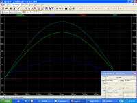
So, I ran the Allison V6 sim at 26v in 4r0 load. Each output transistor produced a the same 6.499A pk, but the pnp driver had to produce approx 97ma current vs the npn at 87ma pk. Plots attached.
Interesting...
Probably not over taxing the driver, but, I'll have at what happens when I turn up the wick.
Ken
Attachments
Ok, so, I wasn't goofy after all...
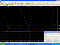
Here's the plot for the pnp - V(be2) vs Ie(Q2) not Ic(Q2). If I put Ic(Q2) into the bottom of the graph, I don't get a line... and the Ie(Q2) vs V(be2) looks like the plot in the data sheets. Thoughts?
Ken
Here's the plot for the pnp - V(be2) vs Ie(Q2) not Ic(Q2). If I put Ic(Q2) into the bottom of the graph, I don't get a line... and the Ie(Q2) vs V(be2) looks like the plot in the data sheets. Thoughts?
Ken
What are you talking about? Which transistor, and what are you trying to do with it?
Looks like it's working right though.
With the way the simulation is set up, it's impossible to put Vbe on the X-axis. I think I remember being able to do Ic vs. Vbe though...
- keantoken
Looks like it's working right though.
With the way the simulation is set up, it's impossible to put Vbe on the X-axis. I think I remember being able to do Ic vs. Vbe though...
- keantoken
What are you talking about? Which transistor, and what are you trying to do with it?
Looks like it's working right though.
With the way the simulation is set up, it's impossible to put Vbe on the X-axis. I think I remember being able to do Ic vs. Vbe though...
- keantoken
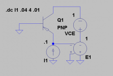
For the pnp tranistor, sorry, I renamed it Q2 with the npn being Q1. Schematic attached
Have a look at the prior plot, at the bottom, it is Ie(Q2) not Ic(Q2).
Attachments
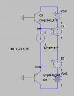
Look at the current source I1. Why not rename this to Ie? E2 and E3 don't draw any current.
I'm going to see if I can make a better fixture...
- keantoken
I'm going to see if I can make a better fixture...
- keantoken
Version 2.1!
Changes:
1: G for tranconductors was decreased.
2: Node names modified to be less redundant.
3: .op simulation command added with instructions for the use thereof.
4: PNP transconductor reversed, so that Ib2 plots correctly as a negative value.
Bugfixes:
1: Certain transistors would cause it to malfunction, this was fixed by decreasing the G's. If any errors result, this value should be decreased to see if that fixes the issue.
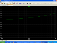
I think a Vce sweep for viewing Vaf is possible as it is, but I think it could be modified to be made more intuitive.
- keantoken
Changes:
1: G for tranconductors was decreased.
2: Node names modified to be less redundant.
3: .op simulation command added with instructions for the use thereof.
4: PNP transconductor reversed, so that Ib2 plots correctly as a negative value.
Bugfixes:
1: Certain transistors would cause it to malfunction, this was fixed by decreasing the G's. If any errors result, this value should be decreased to see if that fixes the issue.
I think a Vce sweep for viewing Vaf is possible as it is, but I think it could be modified to be made more intuitive.
- keantoken
Attachments
Version 2.2! (wow, these updates come fast...)
Changes:
1: Changed from current driven base to voltage driven.
2: Added Vbe compensation. Now there is no variation in Vce caused by Vbe. This has the added feature that you can change from Vce mode to Vcb mode.
3: Various cosmetic changes, added instructions, etc.
Bugfixes:
1: I found that during an AC analysis to view Ft, the increased Ib at high frequencies was causing Vce to modulate as well, throwing off Ft measurements. To fix this, I changed from current source driven base to voltage source driven. This also gave rise to a new feature.
(and no, I don't get tired of this...)
- keantoken
Attachments
- Status
- Not open for further replies.
- Home
- Design & Build
- Software Tools
- BJT SPICE Models, reality-check