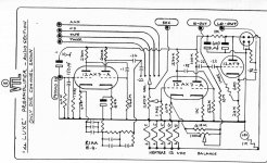
For this preamplifier I need schematic diagram
I don't find a download aera about
Music creates the dimension
and
Manley_Laboratories_Hi-Fi_Main_Page
perhaps one of you know, where I can ask - thank you very much.
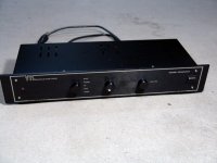
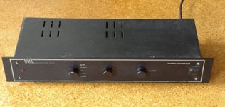
in the attachement some pictures of this preamp:
I don't find a download aera about
Music creates the dimension
and
Manley_Laboratories_Hi-Fi_Main_Page
perhaps one of you know, where I can ask - thank you very much.
in the attachement some pictures of this preamp:
Attachments
Have you checked with VTL? Manley Labs and VTL are completely separate companies now.
I can't tell from looking at it whether you have U.S. built VTL product or an earlier U.K. built VTL product. Unfortunately I no longer remember which models were made where either.. (It's been at least 10yrs since I last worked on a VTL product.)
You might have to ask their service department directly for a schematic.
Edit: I have to say looking at the inside shots it doesn't look much like the U.K. made products I saw which had excellent build quality.
Last edited:
.......
perhaps one of you know, where I can ask - thank you very much.
.....
ask ZM

in case that you have one in front of you - you can send me missing values in phono feedback loop

Attachments
Thank you for your comments and the schematics. This preamp was ordered arround 1990 by tube audio professional
tube audio professional [Atelier Rainer Roeder]
in a modified version (only cap devices in enhanced quality against the serial caps - not changed/modified circuit topology)
I know, that Manley Labs and VTL now are completely separate companies (look at my webaddresses at post #1)
But in those aera, where this preamp device was developed, David Manley works still yet for VTL and he was also the developer of VTL's "Maximal" - so I think.
But neither VTL nor Manley Labs can send me the schematic or an according download aera some months ago. This was the reason to start this thread.
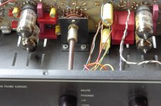
If you see by photo of inside view (solder view of PCB), the missing values in phono feedback loop I can send you only, if I dissass'y the main PCB complete - there are connections between the rear outsite pannel and PCB about the cinch (chynch) female connectors (only approximately 5mm distance) !!! The most devices are between the PCB and rear panel and I want definitely to avoid to disass'y this worse mechanical design.
If I have a complete schematic so as a assembly arrangement and PCB layout/insertion printing, then I can introduce a interface for an outdoor power supply without remooooove the main pcb from the enclosure.
Who is ZM ??
tube audio professional [Atelier Rainer Roeder]
in a modified version (only cap devices in enhanced quality against the serial caps - not changed/modified circuit topology)
I know, that Manley Labs and VTL now are completely separate companies (look at my webaddresses at post #1)
But in those aera, where this preamp device was developed, David Manley works still yet for VTL and he was also the developer of VTL's "Maximal" - so I think.
But neither VTL nor Manley Labs can send me the schematic or an according download aera some months ago. This was the reason to start this thread.
If you see by photo of inside view (solder view of PCB), the missing values in phono feedback loop I can send you only, if I dissass'y the main PCB complete - there are connections between the rear outsite pannel and PCB about the cinch (chynch) female connectors (only approximately 5mm distance) !!! The most devices are between the PCB and rear panel and I want definitely to avoid to disass'y this worse mechanical design.
If I have a complete schematic so as a assembly arrangement and PCB layout/insertion printing, then I can introduce a interface for an outdoor power supply without remooooove the main pcb from the enclosure.
Who is ZM ??
Last edited:
......
Who is ZM ??
who else than : http://www.diyaudio.com/forums/members/zen-mod.html
in any case - if you ever stumble upon these missing values , don't forget me ...
😉
ask ZM
in case that you have one in front of you - you can send me missing values in phono feedback loop
It's pretty much a 45 year old Dynaco PAS circuit dressed up with a nice front panel. The values from that would work fine.
who else than : http://www.diyaudio.com/forums/members/zen-mod.html
in any case - if you ever stumble upon these missing values , don't forget me ...
😉
Ok. ZM = abbrevation of "ZEN MOD" - that was new for me (I cannot mind all abbrevations over this world).
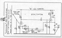
I have found a hand sketched part of the circuit and I recall, that I have measured the resistance DC values in order to avoid the disass'y of PCB.
Since you are professional electronic man, it is easy for you to calculate the values for the capacitors according to receive the appropriate RIAA equalizing frequency response
Attachments
Yes the circuit is simple looking, but their sonic quality was in the execution. Very careful attention to detail. Chassis design was for sound, not ease of repair. Probably some mount of justification for the price as well. If I remember, they were horribly expensive. Compare a PV-5 with a PAS-3. Again, execution.
Yes the circuit is simple looking, but their sonic quality was in the execution. Very careful attention to detail. Chassis design was for sound, not ease of repair. Probably some mount of justification for the price as well. If I remember, they were horribly expensive. Compare a PV-5 with a PAS-3. Again, execution.
I worked on a few Deluxe and in my opinion this model sounded in no way particularly special - not horrible, but not great either, unfortunately it wasn't particularly reliable, nor was it well put together. I have heard and worked on the Maximal as well and wasn't impressed. IMO there was nothing special about the chassis, I think design choices were greatly dictated by aesthetic considerations, and there was no real mechanical isolation between the case, pcb, and tubes - these were quite prone to microphonics. People loved tweaking these with expensive acoustical isolation devices -- needn't wonder why... 😛 U.K. versions were very well put together, the later U.S. built ones weren't nearly as nicely executed. (Not even close) Regardless these pre-amps are very traditional in their electrical design approach and their sound is well... traditional... 😀😀 One thing I will say for them is that they were a bit less expensive than most of the competition so they did offer reasonably good value IMO as an introduction to tube sound. (Most of the people I serviced these for were first time tubies, and soon moved on to other pre-amps.)
Last edited:
Yes the circuit is simple looking, but their sonic quality was in the execution. Very careful attention to detail. Chassis design was for sound, not ease of repair. Probably some mount of justification for the price as well. If I remember, they were horribly expensive. Compare a PV-5 with a PAS-3. Again, execution.
What means "sonic quality was in the execution" ?
perhaps "only average sound quality" ?
The printed wiring board of the whole PCB of this preamp also needed (to avoid the disass'y from the rear pannel).
Either component site view or solder site view (at best both).
Where I can get this?
Either component site view or solder site view (at best both).
Where I can get this?
Yes the circuit is simple looking, but their sonic quality was in the execution. Very careful attention to detail.
That was not the case for the one i had... very early version thou.
dave
That was not the case for the one i had... very early version thou.
dave
Wasn't the case for most VTL stuff I have looked at frankly and the sound was not so hot either.. I've been into DIY for so long that I no longer follow the majors to any degree, getting to hear something commercial just often enough to know I am happy where I am.. 😀
Wasn't the case for most VTL stuff I have looked at frankly and the sound was not so hot either..
In the end we gutted it and built something else inside.
dave
Yes the circuit is simple looking, but their sonic quality was in the execution. Very careful attention to detail. Chassis design was for sound, not ease of repair. Probably some mount of justification for the price as well. If I remember, they were horribly expensive. Compare a PV-5 with a PAS-3. Again, execution.
One more reason to publish a proper service manual
More important than schematic for me is now the printed wiring board of the whole PCB of this preamp (solder site).
I still don't get reply from mail@vtl.com (Music creates the dimension) and also not from gmleng@earthlink.net so as brad@transaudiogroup.com (found by Manley_FAQ_Frequently_Asked_Questions)
Because I don't know who of both will provide currently technical support and repairs from these two companies I contact both.
Perhaps the reason for "no-reply" are outdated e.mail addresses though not updated websites. Perhaps one of you knows more.
Last edited:
Not to be a curmudgeon about it, but I would be surprised if either company offered to provide technical support for this product. I was unable to get schematics for VTL amplifiers I was fixing even when they were current, this unit is something like 25yrs old - and it's designer died a while ago unfortunately.
Perhaps a (very) poor analogy but it might be a little like going to an OPEL dealer and asking for a new factory service manual for an early '80s Opel Commodore...
You need to tackle this on your own or find someone who can.
Perhaps a (very) poor analogy but it might be a little like going to an OPEL dealer and asking for a new factory service manual for an early '80s Opel Commodore...
You need to tackle this on your own or find someone who can.
Unwanted Short Wave Reception by select the Phono-Input
A friend of me observe issues regard that - go to post #14 about
http://www.diyaudio.com/forums/anal...tion-broadcast-sw-stations-2.html#post3166962
A friend of me observe issues regard that - go to post #14 about
http://www.diyaudio.com/forums/anal...tion-broadcast-sw-stations-2.html#post3166962
- Home
- Amplifiers
- Tubes / Valves
- Schematic wanted for VTL Preamp "Maximal"