Hi Telstar,
I would like to clarify something. These three issues are all different:
1) test the design/circuit
2) test the pcb layout
3) test the manufactured pcb
1) This tries to establish whether the circuit itself works up to the desired specifications. I know it's too much to read, tons of pages, but we have been doing a lot towards this goal. Not only simulations, but built several actual prototypes. Measured noise and line rejection to the best of my ability. Compared with other regulators that I built (other designs). Stormsonic has also done some tests. Hifinutnut also built the design and has done some of his tests. I would have loved to send a built regulator to syn08 or Jan Didden to test, because these two guys have both the tools and the skills to run proper tests. syn08 has me on his ignore list. Jan Didden has shown absolutely no interest in this regulator. In any case, the design has been tested for stability by more than one person, has also been tested for normal functionality, and measured to some extent. The only thing we lack are state of the art measurements.
2) I have etched pcbs myself, manually, to test the layout design. Built several, they all worked.
3) The purpose of this test is only to check that the pcb manufacturer has done a good job. I do understand though that many members would feel much better to see the design tested again at this point. But I expect no design changes at this point.
If people have trust issues with the design then we should not do a group buy. I'm serious. We should stop the GB or delay it, and wait until people are happy with whatever measurements and tests.
No, sorry, you're not wrong. I misunderstood what keantoken said. At some point he said that his scope has internal noise of 10uV, and that would not compete with my 100uV/cm scope. However, his 3a9 diff amp module has 10uV/div as the most sensitive setting, and that is better than my 100uV/cm. This being said, I truly do not believe that many of us will achieve lower noise than 20-30uV peak-to-peak ripple. It's just my opinion after doing a lot of these and my own measurements.
Iko
I understand you point of view , but please take a note that everyone from us belive you made an excellent job.
So I would rather think that way
We (members ot this thread) support you with the statement , that the final regulator ( circiut and layout) shows excelent quality / price ratio,
( taking into the account lack of any exotic parts used )
Cosidering above we (and specially you iko as constructor) challenge some EE to show us ( with the support of the tests) that we could be wrong in our belive.
As always where there is a challenge , it should be some arward.
In this case the additional fee calculated per board would build some sort of arward budget
Hi Iko,
Please let me ask to a friend capable to do very good measurements, he is working all day with mechanical robots for medical labs, he has all we needs but first to offer I have to ask him if can do me the help.
Please let me ask to a friend capable to do very good measurements, he is working all day with mechanical robots for medical labs, he has all we needs but first to offer I have to ask him if can do me the help.
no problem Merlin, as you can see its some pretty serious PCB action going on there; i'll let you know how the I/V stage board goes, will be doing it in 3-4 weeks
ikoflexer, no problem, just say the word and i'll PP you
ikoflexer, no problem, just say the word and i'll PP you
I understand you point of view , but please take a note that everyone from us belive you made an excellent job.
So I would rather think that way
We (members ot this thread) support you with the statement , that the final regulator ( circiut and layout) shows excelent quality / price ratio,
( taking into the account lack of any exotic parts used )
I second this statement.
Would´t it be a good idea to integrate the mountings for a SK104 heatsink?
For those who want to place the pcb not at a side of a enclose, this makes it much much easier. 😉
For those who want to place the pcb not at a side of a enclose, this makes it much much easier. 😉
Thks for advice🙂
Could you test the Iko regs. please?
Out of curiosity I already did, in simulation and practice. They are both a living disaster in terms of performance and stability.
But apparently they "sound good", so who am I to debate this "design".
Then why not show the results of your measurements?Out of curiosity I already did, in simulation and practice.
Great! How did you setup the practice part?Out of curiosity I already did, in simulation and practice.
Could you specify that? Specially the performance?They are both a living disaster in terms of performance and stability.
Well, then don't. But could you give us some figures?But apparently they "sound good", so who am I to debate this "design".
you cannot come in here and say such a thing without backing it up, without this it is tantamount to trolling
I have already posted the simulation results here.
http://www.diyaudio.com/forums/powe...e-shunt-voltage-regulator-40.html#post2017916
Under 55dB open loop gain, 100KHz unity loop gain frequency and 35 degs phase margin are recipes for disaster. Your analog stages have usually 1-2MHz unity loop frequency and anything under 60 degs of phase margin is considered potentially unstable. There's a long discussion about the impact of the output cap on this crap, I may expand, but I guess anybody with a LTspice and knowledge about the Middlebrook method of determining the loop gain can replicate these results. Sorry, I don't use LTspice so I can't post the files.
Experimentally, I've build the pos regulator, dead bug. I decided for the "opamp method" (that is, an opamp injection device) described here:
http://cp.literature.agilent.com/litweb/pdf/5989-6304EN.pdf
to measure the loop gain and phase margin, using my 89410A VNA. AD829 video opamps were employed. The experimental results confirmed the simulation to +/-20%: loop gain was actually lower at about 50dB, phase margin was 41 degs and unity loop gain frequency about 125KHz.
In both simulation and experiment I used IRF610/IRF9610. I have no reason to believe that other similar MOSFET types will dramatically impact the results.
BTW, the poor stability is the reason why you guys got some trouble in determining the best place to connect the output cap.
I'll be back with the output impedance results (have to look for the results in my files), if memory serves it was slightly under 100mohm in the audio band, in a stable configuration.
Sincerely,
Your best troll
Last edited:
no problem Merlin, as you can see its some pretty serious PCB action going on there; i'll let you know how the I/V stage board goes, will be doing it in 3-4 weeks
ikoflexer, no problem, just say the word and i'll PP you
Which I/V are you doing?
I have this Erno's Borbely:
An externally hosted image should be here but it was not working when we last tested it.
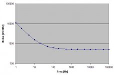
Noise measurements
I've found the noise measurements, see attached.
510nV/rtHz plateau noise, up to 11,000nV/rtHz at very low frequencies (1Hz). Corner frequency is around 100Hz, not bad.
This is in my book "noisy as hell". Imagine you would try to feed a MC stage with this regulator. To keep the power supply negligible, the MC stage would need a HF PSRR of not less than 60dB. There's not many low noise opamps with such a PSRR, for a full discrete low noise design that's almost impossible to get.
Attachments
Wow, look at that. I go out for a bit and hell breaks loose 🙂
Now, how do I respond to this being on his ignore list? Well, let's do it anyway.
Things don't add up syn08. I've already told you that your loop gain analysis was wrong. You probably didn't check it again because you cannot see my replies.
Regarding the noise. This circuit has as its basis Salas' v1 circuit, with very few parts added. The most important modification was one transistor to make the first gain stage of the error amp cascode, and the buffer right after it, another bjt. A lot of people, probably hundreds, have built the Salas circuit and all have reported "black background" and described it as the lowest noise regulator they used. Does it make sense that a couple of extra transistors would make the noise so huge that it's a disaster? Not to me.
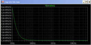
I also attached a simple noise simulation of the circuit. I know very well it's just a simulation. But this noise simulation shows better results (i.e. lower noise) than most regulator designs out there. How can reality be 300 times worse than the simulation? Again, it doesn't make sense to me.
Now, the output impedance. 100mOhm? I have measured it up to about 50kHz with my totally non professional devices and a layout that I wasn't even careful about, on purpose, and it was way below 10mOhm. I don't remember exactly the number but now I want to do it again and write it down.
I've described it before, but this is how I measured the output impedance manually. I used a mosfet as load, biased with two resistors so that there was a DC load of about 100mA. Then I injected a sine wave (also tested with square wave, but the measurement was easier with sine wave) into the gate such that the AC component of the load was about 20mA. I have tried other values as well, like 200mA DC + 50 to 100mA AC, etc. Measured the ripple on the regulator output and divided by the current, at a few frequency points, such as 100Hz, 500Hz, 1kHz, 3kHz, 5kHz, 10kHz, 15kHz, 20kHz, 30kHz, 40kHz, and 50kHz.
I had to do it this way because I just don't have the instruments to sweep over the frequency and just get a plot. That would be nice.
In any case, in my opinion you must have made a mistake somewhere syn08.
However, I think it would be best to delay the group buy until there are measurements that satisfy people. I don't want anybody to be unhappy.
And now more people are reading this thread than before, so I will repeat. I have built all the major designs that I could find a schematic on the web for. The one that finally had the right sound was salas' That's the reason I continued with it as the basis for this design here. I know syn08 always laughs at people because they talk about the "sound." Well, I don't even think I have good ears like most people around here. But even I could hear the difference between the Salas regulator and the Jung super regulator. It wasn't even subtle. I'm sorry, the Jung regulator is a great design and I recommend it to everyone, but I liked Salas' regulator more.
Now, how do I respond to this being on his ignore list? Well, let's do it anyway.
Things don't add up syn08. I've already told you that your loop gain analysis was wrong. You probably didn't check it again because you cannot see my replies.
Regarding the noise. This circuit has as its basis Salas' v1 circuit, with very few parts added. The most important modification was one transistor to make the first gain stage of the error amp cascode, and the buffer right after it, another bjt. A lot of people, probably hundreds, have built the Salas circuit and all have reported "black background" and described it as the lowest noise regulator they used. Does it make sense that a couple of extra transistors would make the noise so huge that it's a disaster? Not to me.
I also attached a simple noise simulation of the circuit. I know very well it's just a simulation. But this noise simulation shows better results (i.e. lower noise) than most regulator designs out there. How can reality be 300 times worse than the simulation? Again, it doesn't make sense to me.
Now, the output impedance. 100mOhm? I have measured it up to about 50kHz with my totally non professional devices and a layout that I wasn't even careful about, on purpose, and it was way below 10mOhm. I don't remember exactly the number but now I want to do it again and write it down.
I've described it before, but this is how I measured the output impedance manually. I used a mosfet as load, biased with two resistors so that there was a DC load of about 100mA. Then I injected a sine wave (also tested with square wave, but the measurement was easier with sine wave) into the gate such that the AC component of the load was about 20mA. I have tried other values as well, like 200mA DC + 50 to 100mA AC, etc. Measured the ripple on the regulator output and divided by the current, at a few frequency points, such as 100Hz, 500Hz, 1kHz, 3kHz, 5kHz, 10kHz, 15kHz, 20kHz, 30kHz, 40kHz, and 50kHz.
I had to do it this way because I just don't have the instruments to sweep over the frequency and just get a plot. That would be nice.
In any case, in my opinion you must have made a mistake somewhere syn08.
However, I think it would be best to delay the group buy until there are measurements that satisfy people. I don't want anybody to be unhappy.
And now more people are reading this thread than before, so I will repeat. I have built all the major designs that I could find a schematic on the web for. The one that finally had the right sound was salas' That's the reason I continued with it as the basis for this design here. I know syn08 always laughs at people because they talk about the "sound." Well, I don't even think I have good ears like most people around here. But even I could hear the difference between the Salas regulator and the Jung super regulator. It wasn't even subtle. I'm sorry, the Jung regulator is a great design and I recommend it to everyone, but I liked Salas' regulator more.
Attachments
I should add, everywhere I looked, to have a stable circuit, the engineering "rule of thumb" for phase margin value is a minimum of 45, not 60, although 60 is used as a typical aim.
Don't worry Iko, I trust you, so I buy your pcbs. About test I am sorry mine friend is very busy & can't do it in a very reasonable time so can't count in him.
I should add, everywhere I looked, to have a stable circuit, the engineering "rule of thumb" for phase margin value is a minimum of 45, not 60, although 60 is used as a typical aim.
Hi,
If the circuit on page one of this thread is the correct up to date one, it would not simulate stable for me.
Hi,
If the circuit on page one of this thread is the correct up to date one, it would not simulate stable for me.
It's the one in Iko signature (pos and neg version).
It's the one in Iko signature (pos and neg version).
Link is just taking me to this page...😕
- Status
- Not open for further replies.
- Home
- Amplifiers
- Power Supplies
- My take on a discrete shunt voltage regulator