I shall go for differential any time. And you can go for both.
The slowest process is the reclocking (D-FF).
The fastest D-FF you can get is 10EP52, which is differential, and also smallest jitter.
The disadvantage is that you need 4 of them, which makes clock connection a bit tricky.
ECL is supposed to be P2P and not daisy chain.
> Perhaps with some tricks the DAC chips will reliably switch directly from PECL.
With 800mV level switching for PECL or NECL, it is a bit tricky. You would need some amplification.
The people at Micrel or Onsemi are not idiots. I doubt we can do any better.
Patrick
The slowest process is the reclocking (D-FF).
Do you mean the translator ( slower ) does not matter ?
Please explain.
With 800mV level switching for PECL or NECL, it is a bit tricky. You would need some amplification.
The people at Micrel or Onsemi are not idiots.
Onsemi makes some of the finest digital chips money can buy 🙂
But they need to offer universal failproof troublefree solutions. 😉
Just tested:
My DAC chips accept high levels down to 1,70 V.
The datasheet asks for 2,4 V.
Let's see what about the low level.
> Do you mean the translator ( slower ) does not matter ?
Of course it matters, because it is (at least from ECL to TTL) the biggest jitter contributor.
But then we were discussing differential or speed, and not jitter, a while ago.
For me, power supply (or ground bounce) sensitivity also contributes to extra jitter. And you can reduce that a lot by differential.
> But they need to offer universal fail-proof trouble-free solutions.
You mean they are not reliable ?
Have you tried Micrel ?
I am very tempted to use Micrel at half the price.
Patrick
The PCM56 seems to have a very tight switching point of 1,7V.
Low level voltage of 1,6 V still seems to work.
I will make a final test with low logic swing.
The 0,8 V from PECL should be more than enough. I hope.
Low level voltage of 1,6 V still seems to work.
I will make a final test with low logic swing.
The 0,8 V from PECL should be more than enough. I hope.
You probably would need to have very low ground noise (which eats out of the 800mV budget), and a super fast level shifter ( probably a resistor network with a coupling cap with resonance above say 20MHz), and then you can drive directly from the D-FF, which would of course be great news.
Patrick
Patrick
No, I meant that they need to offer something like a translator that works 100% in every application.
They would not tell you to try to match the two families with tricky glue.
But that does not necessaryly mean that it is impossible.
Obviously it is not possible to make faster TTL translators abd that for sure has to do with the large voltage swing.
Still I do not understand what did you mean with:
The slowest process is the reclocking (D-FF).
What is slow here ? What is faster ?
Also, don't you think there is a relation between speed and jitter ?
Faster ECL usually has less Jitter ?
I will put antiparallel diodes into the bitclock line to reduce swing for testing, hope that works.
> Still I do not understand what did you mean with:
> The slowest process is the reclocking (D-FF).
The D-FlipFlop has the largest propagation delay in the whole chain, I tried to say.
My belief is that the larger the propagation delay, the larger will be the jitter.
It is certainly easier to keep a 100ps conversion process (whatever it is) constant to 1ps, than to keep a 500ps process constant to 1ps.
So if I want to improve jitter of the entire process, I would start at the component with the highest jitter first; and my suspect is still the D-FF and probably then the translator. But the D-FF is all ECL, whereas the translator is mixed. So maybe the translator is still the largest contributor to jitter, even though the propagation delay is less than the D-FF.
But maybe the experts from Onsemi can give you the real answer. It depends on what is really inside the chip, and how the translation is done.
Also I would be very interested to know what the jitter figures are in the audio band (10Hz to 40kHz) and not only cycle-to-cycle.
Patrick
Last edited:
The D-FlipFlop has the largest propagation delay in the whole chain, I tried to say.
But the translator is also in the chain.***
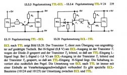
The translators: ELT21 has 3,5 ns tpg and the H125 2,5 ns, while the flipflop E131 that I use at the moment has only 0,5 ns tpg.
My belief is that the larger the propagation delay, the larger will be the jitter.
It is certainly easier to keep a 100ps conversion process (whatever it is) constant to 1ps, than to keep a 500ps process constant to 1ps.
Agreed. Plus: Rise time, propagation delay and max. clock speed are all in relation. More or less.
So if I want to improve jitter of the entire process, I would start at the component with the highest jitter first; and my suspect is still the D-FF and probably then the translator.
Why, if the flipflop is faster ?
But the D-FF is all ECL, whereas the translator is mixed. So maybe the translator is still the largest contributor to jitter, even though the propagation delay is less than the D-FF.
Again, where is the pgd less ???????????????
*** Not for so long anymore, I guess.
This is the bitclock with adjusted logic swing from ca. 1,45 V to 1,95 V.
Makes 0,5 V logic swing and works.
There are artefacts when I reduce it further, it is now biased to ca. 1,7 V.
Perhaps the swing could be reduced further when the bias voltage is also adjusted to the exact middle point.
That would mean that I either switch to PECL completely or find a fast NECL to PECL translator that I can use as distributor and buffer at the same time.
But now I want to use that first reclocker for some time ...

Last edited:
You probably would need to have very low ground noise (which eats out of the 800mV budget), and a super fast level shifter ( probably a resistor network with a coupling cap with resonance above say 20MHz), and then you can drive directly from the D-FF, which would of course be great news.
LVPECL ( 3,3V ) is very close to what I need with minimal or no level shifting at all.
Also the EL89 provides double = 1,6 Vpp output swing.
But the DC levels in the datasheet are either wrong or I don't understand something here.
I need buffers to drive a total of 32 DAC chips, a single flipflop per data/bitclock/LE won't do it.
Without translators it will be by far the fastest and lowest jitter reclocker that has ever been built for audio, if not already. 😎
Last edited:
You are right with the translator slower than the FF. I misread the data sheet.
As to EL89, 1.6Vpp is differential (output+ve - output-ve), so it is still 0.8V single ended, which you need to use to drive the DACs direct. Then no point using EL89, as it has worst jitter than EL11 (if I remember correctly).
As to LVPECL, it has the right DC voltage level, but only 250mV swing, and the centre voltage changes with temperature. So I am sceptical (may work, but not robust solution). But perhaps worth trying. In any case great progress. Congradulations.
I am planning to use PCM1704, which is supposed to be 2V/0.8V per data sheet.
I guess it might be similar to PCM56 ??
BTW How are you shifting the logic level & setting the bias voltage right now ?
Patrick
Last edited:
You are right with the translator slower than the FF. I misread the data sheet.
As to EL89, 1.6Vpp is differential (output+ve - output-ve), so it is still 0.8V single ended, which you need to use to drive the DACs direct. Then no point using EL89, as it has worst jitter than EL11 (if I remember correctly).
As to LVPECL, it has the right DC voltage level, but only 250mV swing, and the centre voltage changes with temperature. So I am sceptical (may work, but not robust solution). But perhaps worth trying. In any case great progress. Congradulations.
I am planning to use PCM1704, which is supposed to be 2V/0.8V per data sheet.
I guess it might be similar to PCM56 ??
BTW How are you shifting the logic level & setting the bias voltage right now ?
The DC levels in the EL89 datasheet that is inside the highperformancedata.pdf are wrong.
I will only download the newest datasheets in future.
3,98 V high - 2,3 V low makes 1,68 V swing.
For example the LVEL90 ECL to LVPECL translator @ Vcc = 3,3 V has 2,345 V high - 1,6 V low makes 0,75 V swing, centered to 2 V.
@ Vcc = 3 V the swing is 0,75 V centered to 1,7V. That is exactly what I need. But I still consider other solutions.
I would just test the PCM1704 to be sure.
My test setup was 2 x 1N4148 + 1 x BYT08P in series plus the same antiparallel and the whole thing inserted into the clock line. 910 ohm to + 5V and 500 ohm to ground on the DAC input for bias. Optional a variable resistor in the 220 ohm range for fine tuning across one or both of the BYT08.
A test to find the exact switching point could be to leave the bitclock input open and bias to an adjustable voltage. When playing music, the DAC will output white noise in the metastable area. The best switching point would be located in the middle.
> 3,98 V high - 2,3 V low makes 1,68 V swing
Indeed. This is more than required for TTL inputs.
Only need to shift from 3.2V midpoint to 1.4V midpoint; one red LED, e.g.
😉
Patrick
Indeed. This is more than required for TTL inputs.
Only need to shift from 3.2V midpoint to 1.4V midpoint; one red LED, e.g.
😉
Patrick
Bernhard,
Take a look at MAX9404.
I don't know where to get it, but it looks like a very interesting device.
One can reclock and output to drive the PCMxxs direct.
MAX9401, MAX9404 Quad ECL/PECL Differential Buffers/Receivers
Patrick
Take a look at MAX9404.
I don't know where to get it, but it looks like a very interesting device.
One can reclock and output to drive the PCMxxs direct.
MAX9401, MAX9404 Quad ECL/PECL Differential Buffers/Receivers
Patrick
Only need to shift from 3.2V midpoint to 1.4V midpoint; one red LED, e.g.
Maybe we can manage to use blue LED ?
Take a look at MAX9404.
I don't know where to get it, but it looks like a very interesting device.
One can reclock and output to drive the PCMxxs direct.
Thanks, could save a lot of work if it wasn't so small. 5 x 5 mm 😱
Also what I see, it uses 2 unnecessary gates per signal path.
And, do you think one output can drive 32 Latch Enable inputs ?

If you make a pcb for the small chip it might work for you.
Keep me updated if you find something interesting.
Last edited:
What about a feature for the front panel ?
A scope that displays the data stream or something like that.
A scope that displays the data stream or something like that.
A 80 cent solution for the TQFP package :
Sockets - SMD Adapters
The problem is where to get the thing. It is everything in one that I would need. (I just asked Maxim.)
What a mess in comparison to do it with 4 individual D-FFs with unspecified device-to-device skews, and 4 clock lines.
This thing has a in-device skew of 1ops.
Are you trying to tell me LEDs are too slow as level shifter ?
I thought they can do 1MHz+ easy, and I have no MCLK to the PCMs. Also it is always conducting, right ?
If you use a cap and a potential divider as in AND8020, you also need to find a cap with resonance above 30MHz or so, right ?
Patrick
I am listening to the previous version with less ideal grounding and it sounds a bit better than a pair of industrial clocks, however I have no specs or datasheets from manufacturers.The influence on sound.The clock is located inside the DAC and it fixes all the typical degradations caused by SPDIF & bad CD player clocks, for example corrupted tonal balance, irritating sound, lack of precision and separation.
I don't like the superlative vocabulary that is used regularly in this place 😉
The clock frequency has nothing to do with TDA1541, it is just comfortable to divide down to what my transport expects as word clock.
What is important with any clock: The oscillator part must be shielded. Otherwise it will pick up all the noise it can get, you can see it on a spectrum analyzer.
Industrial clocks are not put into hermetically sealed metal cases for fun or for the shiny look.
- Status
- Not open for further replies.
- Home
- Source & Line
- Digital Source
- differential clock