Got a PSX that's blowing a fuse when switched on (FS2). All else seems fine. On/off switch lacks a positive action so I'm thinking that may be the culprit. Has anybody ever replaced the switch? Any suggestions for a replacement?
HI there,
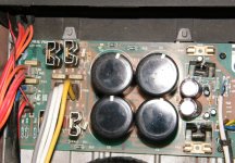
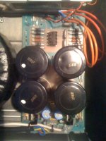
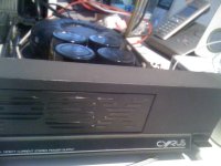
after having restored my beloved Cyrus II succesfully, I want to go for servicing my PSX unit which I acquired some month ago. It is the toggle switch version with the Holden&Fisher toroid and Slit-Foil caps. The PCB is missing the diode D16 😱. Anybody got an idea which value to solder in here? Is this diode needed here or not? I have the Cyrus 1/2 service manual, is there a PSX service manual existing as well?
Thanks in advance for any input here!
Best regards and merry x-mas to all!
Rad
My PSX is the latest metal/toggle version and I can only find up to D15 labelled on the PCB. Where is your D16 supposed to be? 😕
Hi Sonusthree,
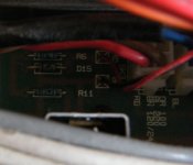
Diode D16 is located above the red and black cables for the red led above the toggle power switch in front. Below D16 is an resisitor R11. As already stated the diode is missing here... Any clue?
Thanks and best regards
Rad
Diode D16 is located above the red and black cables for the red led above the toggle power switch in front. Below D16 is an resisitor R11. As already stated the diode is missing here... Any clue?
Thanks and best regards
Rad
Hi Sonusthree,
Below D16 is an resisitor R11. As already stated the diode is missing here... Any clue?
I have no clue!
 I have checked again and my PSX has no D16.
 What is it's function? That will help you determine what is missing. Is it part of the same LED circuit as D15?
Attachments
HI Sonusthree!
My PCB looks different from yours as does the printing on it:
Strange!
I need help attaching a picture to my reply.
Thanks and best regards
Rad
My PCB looks different from yours as does the printing on it:
Strange!
I need help attaching a picture to my reply.
Thanks and best regards
Rad
No, I have located D15 as part of the LED circuit as well on my PCB. It´s there. I still have no idea about D16.
Regards
Rad
Regards
Rad
Hi Sonsthree, thanks a lot for the hint!
OK, here some pics:
http://s4.dastatic.com/forums/images/attach/jpg.gif
http://s4.dastatic.com/forums/images/attach/jpg.gif
http://s4.dastatic.com/forums/images/attach/jpg.gif
Hope that helps!
Best regards
Rad
OK, here some pics:
http://s4.dastatic.com/forums/images/attach/jpg.gif
http://s4.dastatic.com/forums/images/attach/jpg.gif
http://s4.dastatic.com/forums/images/attach/jpg.gif
Hope that helps!
Best regards
Rad
Attachments

Have you looked under the board to see if anything was ever soldered there?
I'm guessing it was never installed and that my board is a later revision. Look under the board at the solder pads and you should be able to tell.
Also my board is issue 1A. Which is yours?
I'm guessing it was never installed and that my board is a later revision. Look under the board at the solder pads and you should be able to tell.
Also my board is issue 1A. Which is yours?
Hi Sonusthree,
I don´t have any clue about the revision of the board since there is no printing on it, neither on top nor on the bottom side.
Strange!
Best regards
Rad
I don´t have any clue about the revision of the board since there is no printing on it, neither on top nor on the bottom side.
Strange!
Best regards
Rad
Hi, is there someone who knows which diode to solder into my PSX pcb? Anyone has a clue why it is missing in my pcb? There is no printing on the pcb, so no idea which rev.?
Thanks for any advice
Best regards
rad
Thanks for any advice
Best regards
rad
Have you looked under the board to see if anything was ever soldered there?
I'm guessing it was never installed and that my board is a later revision. Look under the board at the solder pads and you should be able to tell.
Did you look for solder or evidence of de-soldering?

Hi,
Be aware that there are two versions of the PSX-R, and they look the same. One simply puts out the full voltage and is intended for the amplifier only. The other has a circuit that recognizes what it's plugged in to and adjusts it's output voltages to what is required. They are not interchangeable and I don't know how to tell them apart. I did have to design a jig that allows me to operate the PSX-R through it's various output voltages.
It's really advanced, I am impressed.
The PSX-R improves the performance of the CD players by separating the servo draw from the audio side, there is a digital supply on it's own in the newer machines as well.
Hi angulo,
What you have is simply the Mission version of the Cyrus One. I've fixed many. Basically the same beast in a cast chassis. They went with sheet metal soon after.
Hi Andrew,
Yes, I completely disagree with both increasing the capacitance and especially with using fast recovery diodes. The two changes together will increase the diode switching noise on the supplies.
I have worked on units that have been afflicted with these changes and compared them to stock units. Guess what? No difference in sound quality can be heard or measured. They can't be measured either unless the diode switching is more severe.
I'll tell you straight up, if fast recovery diodes improved anything, industrial electronics would use them by the boatload. They don't. The regular diodes are engineered very well for a balance of efficiency and reduced noise. The only reason the rectifiers exist that you are recommending are for switching power supplies.
We will always disagree on this I guess. I think that the reason these myths come to be is the idea that the manufacturer always designs cheaply. The really sad thing is here is that the people at Cyrus design extremely well, and they do not skimp anywhere.
Do you know what they use for prototyping units Andrew? Real spectrum analyzers and also an Audio Precision II (back in 2004). The service benches are equipped with AP series I. After they design anything, it goes to the listening room for subjective testing. I think you are selling these people short, and that's too bad considering they are one of the most advanced designs out there. Their engineers (who I spoke with at length while I was there) are people who really do understand audio design - including the proper design of the power supplies.
Bedini went all out in some of his amps. The caps stretched the entire depth of the chassis from front to back. A disaster, since they had far too much inductance to even take care of the 120 Hz ripple. Large caps are not the answer, they need to be properly sized and not too large. Sounds like real engineering is required here.
Want further proof? Look at the schematics of test equipment where all noise is bad. You will see they do not use extremely large capacitors.
-Chris
Hi,
i am looking to overhaul my 2 x Cyrus 2 (mono config) + 2 x PSX system. I am really happy with the sound but want to give them their life expectancy back.
Does anyone have a list of which parts to change from and to? That would be really helpful and appreciated.
Also, does anyone know why my Cyrus 2's LED's do not light up? They did before enabling them to work with PSX. It doesn't make any sonic difference but i would prefer them to all look the same.
I will post some pictures in a month or so showing the refurb i will do to the casing as my 2 x Cyrus Ones are at the spray booth as i type awaiting a new Ferrari Red paint job! Mad i know but it will suit the environment they will be in. They will also be fitted with spike feet and each have a marble platform.
Many thanks for any info given.
Just figured out why the LED's are not lighting up - the power cables were faulty. So that is now sorted.
Has anyone got a list of the parts to replace?
Thanks.
Has anyone got a list of the parts to replace?
Thanks.
I wanted to ressurrect this thread because I recently bought a 1st generation, plastic case PSX. Mine is the British unit that is wired for 240V. I opened the case and noticed that the toroidal's primary wires are brown and red, but there's a twisted pair colored blue and black unused. Are those for 120V operation?
I lifted the lid on my PSX - 120 V - the blue & black also the brown & red wires all go into a four pin PCB connector... THere is mating connector on the PCB with a code showing which goes where for voltage conversion - seems one would just turn the connector around 180 degrees and plug back in...?
Now, furthering the thread: I actually have a Cyrus LFAU/PSX combot that goes with the Mission 767 speakers. I seem to be having trouble balancing the low frequencies (woofer drive from the LFAU/PSX) with the mid & high frequencies driven from my main amplifier. I figure it might be low output from the LFAU (PSX output appears O.K.).
Does anyone have experience with this speaker system that might be able to shine a light (or a woof) on my issues??
Thanks...
Hi Sonsthree, thanks a lot for the hint!
OK, here some pics:
http://s4.dastatic.com/forums/images/attach/jpg.gif
http://s4.dastatic.com/forums/images/attach/jpg.gif
http://s4.dastatic.com/forums/images/attach/jpg.gif
Hope that helps!
Best regards
Rad
Hello, sorry for my English, I'm from Russia.
Understand that the topic is old, can you have a photo where the wire does not close the D15, R6. I got the PSX which everything is burned or if it is possible ratings D15, R6, R11
With respect Alexander!
- Home
- Amplifiers
- Solid State
- Cyrus PSX dead