best to have a mechanical switch between dsd and pcm and then make selection in software. If you are using s/w, have it control the mechanical switch
I'm not exactly sure what you mean by this. There are DSD and PCM headers on the board, so wire both those up, then bring out the existing DSD switch that's on the PCB to say the front panel, or bring out a new switch all together and use that to toggle software? How can software "control" a mechanical switch?
I'm not exactly sure what you mean by this. There are DSD and PCM headers on the board, so wire both those up, then bring out the existing DSD switch that's on the PCB to say the front panel, or bring out a new switch all together and use that to toggle software? How can software "control" a mechanical switch?
The PCM and DSD lines connect to the same pins in the DAC, so you need some switch such as the OTTO to switch between pcm and dsd. (it is probably OK to have them both pcm and dsd connected all the time provided you make sure you only have one on at any given time. Keep in mind that a source will still be ON even when not playing music)
If you are using the h/w interface, then you will use one switch to toggle the OTTO and another switch to toggle dsd/pcm. If you use s/w then you can program a single switch to do both. A mechanical switch such as a relay (OTTO) can be controlled with s/w and a controller such as Arduino by pulling the control pin in the relay high or low.
The PCM and DSD lines connect to the same pins in the DAC
really? pin1 is LRCLK for PCM and pin1 is DSDL for DSD. pin22 is unused for PCM and DSDR for DSD. I do see that there is overlap for 2 pins though. Ok, let me think about this some more.
Russ, so the metronome doesn't really play a role with DSD?
with regard to just leaving them connected, either DSD or PCM is selected by the player, so I cannot see how they would both be on at the same time. But, I'm assuming that Russ has tried sending PCM from DSD chip in the Denon, so perhaps a switch is needed?
Otherwise, if I were to use the OTTO I could just hardwire pin22 (DSDR) and then toggle pin1, pin3, *and* the DSD switch with a single OTTO, as there are enough poles on the relay to do this. I'm not sure if I 'd have to remove the DIP switches all together though, or just solder wires underneath... I'm assuming this comes pre-soldered?
Last edited:
I see you plan to use the Denon player. It could be the case that the Denon would turn one off while enabling the other, but not guaranteed. With a switch you will have a more flexible implementation
pin 22 is the OSR pin (for hardware mode) for PCM (OSR controls the DAC's internal oversampling)
pin 22 is the OSR pin (for hardware mode) for PCM (OSR controls the DAC's internal oversampling)
I see you plan to use the Denon player. It could be the case that the Denon would turn one off while enabling the other, but not guaranteed. With a switch you will have a more flexible implementation
pin 22 is the OSR pin (for hardware mode) for PCM (OSR controls the DAC's internal oversampling)
glt: nice website. I cannot seem to find a schematic or connection diagram though for how you hooked up the Arduino to the board, that might be rather handy addition to your website. Seems obvious enough from the code provided perhaps? How large is your code, compiled with -Os (edit: oops, you're using "sketches" and what not, probably this doesn't apply)? How many I/O lines are you using? Point being, could you use one of the smaller Arduino platforms?
luvdunhill, thanks!
I'm using the standard Arduino. I think the code compiled with the Arduino development tool is 8K or so. Plenty of space left. I'm sure you can use any Arduino depending on what you use for LCD. Since I use an I2C LCD, the same two I2C lines controls the DAC and the LCD. I'm using two line for the rotary encoder and I think two lines for the remote receiver. The Arduino connects to the OPUS board like this: H I F I D U I N O: Arduino Controller & DAC after 5v to 3.3v conversion, since the wm8741 is not 5v resistant.
I'm using the standard Arduino. I think the code compiled with the Arduino development tool is 8K or so. Plenty of space left. I'm sure you can use any Arduino depending on what you use for LCD. Since I use an I2C LCD, the same two I2C lines controls the DAC and the LCD. I'm using two line for the rotary encoder and I think two lines for the remote receiver. The Arduino connects to the OPUS board like this: H I F I D U I N O: Arduino Controller & DAC after 5v to 3.3v conversion, since the wm8741 is not 5v resistant.
glt,
Are you using the AD chip to interface the Arduino to the Opus DAC? I read your website and think that is what you are describing.
Is it the AD 1251 chip you have selected?
Are you using the AD chip to interface the Arduino to the Opus DAC? I read your website and think that is what you are describing.
Is it the AD 1251 chip you have selected?
That was the original plan, but too lazy to buy the chip. Right now I just have a level conversion. The Arduino levels are 5V, the DAC levels are 3.3V and the DAC is NOT 5V tolerant. I built the level converter myself: H I F I D U I N O: Implemented 5V to 3.3V I2C level Shifting but you can buy one now: H I F I D U I N O: Logic Level Converter. And then you connect digital gnd from DAC to Arduino gnd.
Looking at the schematics of the little nck board, you use the TX pins, not the RX pins and you connect both 5V and 3.3V to the Arduino board.
Looking at the schematics of the little nck board, you use the TX pins, not the RX pins and you connect both 5V and 3.3V to the Arduino board.
Last edited:
glt,
The parts are on order, so just waiting on the package to arrive.
Happy Holiday's to you and yours! 🙂
The parts are on order, so just waiting on the package to arrive.
Happy Holiday's to you and yours! 🙂
One of which was certainly something like that. I also though about using something with galvanic isolation.
Russ, I think I'll just try the hex inverter approach. I do have a question though, is the DSD signal 3.3V or 5V TTL, and which does the Opus prefer? I'm assuming they are compatible, since you directly connected them. I'm just wondering if I need a 5V or 3.3V supply for the hex inverters (or perhaps a buffer cannot be used for level shifting anyways? I'm rather new to this.) I'm looking to use TI SN74HCU04D.
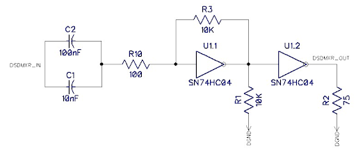
Also, any recommendation on the input caps? Similar application notes I've seen, said they should be used. I was thinking np0 ceramic or similar? I was also thinking about adding a nearby LP2985 and a few caps, as you did on the Opus.
Last edited:
Correct. Opus uses 3.3V for VD and 5V for VA. You will need too use 3.3V for anything digital.
opus module partially dead?
I've got a problem, I fear the module has gone but I accept some suggestions.
My setup:
-2 Opus 8740 based modules in mono mode
-1 spdif receiver module
both dac modules share the ps, analog and digital separated (8Vdc), receiver has its own ps.
-Broskie Cathode Follower output stage bal->se
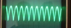
I noted a low volume from left channel yesterday, a rapid check with the scope showed that pins 13 (VOUTRN) and 17 (VOUTLP) in left channel module are mute, so the output stage delivers a 0.5*V signal (1.15Vpp against 2.3Vpp, less than balanced output due to output stage <1 gain).
This condition is true with stereo mode, mono left mode, mono right mode. In stereo mode the signal on 13 and 16 pins is not a complete sine wave (see picture). The other two modules are ok.
I think the 8740 is partially dead, but I'm glad to hear any ideas from you about it.
If the 8740 is dead, is there any chance to swap the IC with a fresh one?
I can set the working module in stereo mode and starting again, but I'm curious to understand what happened.
Thanks.
I've got a problem, I fear the module has gone but I accept some suggestions.
My setup:
-2 Opus 8740 based modules in mono mode
-1 spdif receiver module
both dac modules share the ps, analog and digital separated (8Vdc), receiver has its own ps.
-Broskie Cathode Follower output stage bal->se
I noted a low volume from left channel yesterday, a rapid check with the scope showed that pins 13 (VOUTRN) and 17 (VOUTLP) in left channel module are mute, so the output stage delivers a 0.5*V signal (1.15Vpp against 2.3Vpp, less than balanced output due to output stage <1 gain).
This condition is true with stereo mode, mono left mode, mono right mode. In stereo mode the signal on 13 and 16 pins is not a complete sine wave (see picture). The other two modules are ok.
I think the 8740 is partially dead, but I'm glad to hear any ideas from you about it.
If the 8740 is dead, is there any chance to swap the IC with a fresh one?
I can set the working module in stereo mode and starting again, but I'm curious to understand what happened.
Thanks.
Attachments
It does indeed look as through the chip is dead. As to what happened, it is hard to say.
Is your output stage healthy?
Is your output stage healthy?
I changed the Lp 2985 for the 5 V to New Class D regulator and removed the ferrit perles and ceramic capacitor because the Dac was Screaming at me 😀
What a difference.
What a difference.
Is your output stage healthy?
Thank Brian for your reply,
yes I think so, I'm using the remaining good module in stereo mode now and everything is going smooth. I listened a couple of cds last evening and I should say I prefer the dual mono setup in terms of sound quality especially in the high frequencies.
I suppose it's not a good idea to mix 8740 and 8741 based modules in a new dual mono setup. What do you think?
Is there any chance to replace the dead IC or I've to consider the whole module dead?
in my previous post there was a typo
"....stereo mode the signal on 13 (read 12) and 16 pins is...."
Last edited:
Transformer failure.
Just a heads up. I had a mains transformer supplied with my Opus parts fail on me recently. It ignited internally. Fortunately it caused the windings to go open circuit so there was no major fire.
Just a heads up. I had a mains transformer supplied with my Opus parts fail on me recently. It ignited internally. Fortunately it caused the windings to go open circuit so there was no major fire.

- Home
- More Vendors...
- Twisted Pear
- Mr White's "Opus", designing a simple balanced DAC