another Schroeder clone
This isn't in the same league with Frank's own work of Jeff's recent work, but it confirmed for me that DIY clones are possible and worth the effort.
This isn't in the same league with Frank's own work of Jeff's recent work, but it confirmed for me that DIY clones are possible and worth the effort.
Attachments

Last edited:
More parts coming in, the builds continue....
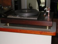
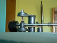
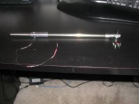
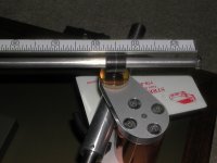
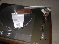
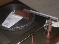
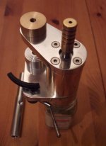
I'm still waiting for the bottom magnet pots, but I decided to mock up the arm on the table to check geometries, etc.. I have a dummy cartridge body I use.
The arm-wand still needs to have the wiring installed, but so far so good. Hopefully by this time next week the arm should go live and put the deck into service.
Attachments

DIY Schroeder Tonearm???
Jeff - those arms are absolutely beautiful. To say I'm envious just shows my inadequacy with the language. If I understand correctly, you had them made to specs you worked out with Frank Schroeder. Is that right? Or did you do the work yourself?
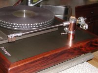
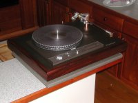
I finished the Schroeder Model I clone in the pictures - using wood for the pivot structure - over the past three weeks. I did it primarily because I was fascinated with the basic Schroeder ideas and also because I wanted to see if a DIY version was feasible. It definitely is. The arm performs far beyond anything I expected.
I'm very curious about the outrigger arrangement on your counterweight. Is that your design?
I'm looking forward to your report after you've had a chance to listen.
Jeff - those arms are absolutely beautiful. To say I'm envious just shows my inadequacy with the language. If I understand correctly, you had them made to specs you worked out with Frank Schroeder. Is that right? Or did you do the work yourself?
I finished the Schroeder Model I clone in the pictures - using wood for the pivot structure - over the past three weeks. I did it primarily because I was fascinated with the basic Schroeder ideas and also because I wanted to see if a DIY version was feasible. It definitely is. The arm performs far beyond anything I expected.
I'm very curious about the outrigger arrangement on your counterweight. Is that your design?
I'm looking forward to your report after you've had a chance to listen.
Attachments
@JD: Nice work, keep posting. I will be getting my arm metal parts this weekend. Why did you go for that sort of counter weight mechanism ?
@Doug: Was that arm lift made by yourself ? Hopes, you can help me to build one... 🙂
Best regards,
Bins Paul.
@Doug: Was that arm lift made by yourself ? Hopes, you can help me to build one... 🙂
Best regards,
Bins Paul.
Thanks,
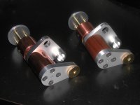
Specs from my own observation and working out the dimensions of what was needed according to the tonearm geometry I wanted using a 10.5" arm and the turntable / plinth I was building. I laid everything out in a CAD program and fiddeled with everything for a few weeks before I was satisfied with everything before I had the pieces made. Main help from Frank was the info I gathered from "this "thread" (read a few dozen times all the way thru) and a pointer or two from an email from him on how a potted magnet works. No hard dimensions.. worked them out myself with a bit of research on the priciples.. I posted earlier the links to that info.
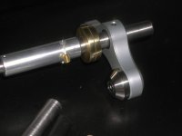
I can not take credit for the outrigger counterweight. It is made by company called "GrooveTracer". It is made for the Rega arm and it's variants. Because I wanted to use this counterweight, I made my endstube the same diameter as the Rega (1/2")
It's available in 110, 130 1nd 150 gram weights, They can make heavier ones on custom order as well as out of Tungsten rather than their standard Stainless Steel. Both have a central block out of aluminum. I did a bit of researching all the forums I could and it was mostly agreed that this was the best for the Rega.. Maybe or maybe not for this arm, but the outrigger design seemed best for this arm becaus of its self balancing low slung weights on each side. It also has a nylon tipped set screw for fixing and a delrin bushing around the end stub, so it has a decoupling effect as well.
If you look at the pics carefully, you'll see a brass ring on the endstub. It can slide back and forth to fine tune the tracking force once the main weight is set. It's a sliding fit and has some friction so it will stay put in whatever position it's put. Groovetracer's website is groove tracer
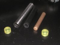
Also, what you cant see in my endstub is a dampning system. The endstub is a thin wall Titanium tube with a silicone plug about 1/4" thick on each end. In between the plugs is a closed cell foam rubber tube and in foam rubber tube is a short solid bronze rod. What this does is completely damp all vibrations on the endstub. If you take a metal tube with no internals and drop it, it will bounce and ring. If you take my endstub and drop it the same distance it just lands with a dull thud and does not bounce at all as all the energy is more or less almost completly dampened. Almost like dropping a rubber ball verses a ball made of Sorbothane. We'll see how this contributes to the sound of the arm, tho I don't have a "control" arm to cmpare it against.. just a bit of intuition here.
here are some more detail shots...
Jeff
Specs from my own observation and working out the dimensions of what was needed according to the tonearm geometry I wanted using a 10.5" arm and the turntable / plinth I was building. I laid everything out in a CAD program and fiddeled with everything for a few weeks before I was satisfied with everything before I had the pieces made. Main help from Frank was the info I gathered from "this "thread" (read a few dozen times all the way thru) and a pointer or two from an email from him on how a potted magnet works. No hard dimensions.. worked them out myself with a bit of research on the priciples.. I posted earlier the links to that info.
I can not take credit for the outrigger counterweight. It is made by company called "GrooveTracer". It is made for the Rega arm and it's variants. Because I wanted to use this counterweight, I made my endstube the same diameter as the Rega (1/2")
It's available in 110, 130 1nd 150 gram weights, They can make heavier ones on custom order as well as out of Tungsten rather than their standard Stainless Steel. Both have a central block out of aluminum. I did a bit of researching all the forums I could and it was mostly agreed that this was the best for the Rega.. Maybe or maybe not for this arm, but the outrigger design seemed best for this arm becaus of its self balancing low slung weights on each side. It also has a nylon tipped set screw for fixing and a delrin bushing around the end stub, so it has a decoupling effect as well.
If you look at the pics carefully, you'll see a brass ring on the endstub. It can slide back and forth to fine tune the tracking force once the main weight is set. It's a sliding fit and has some friction so it will stay put in whatever position it's put. Groovetracer's website is groove tracer
Also, what you cant see in my endstub is a dampning system. The endstub is a thin wall Titanium tube with a silicone plug about 1/4" thick on each end. In between the plugs is a closed cell foam rubber tube and in foam rubber tube is a short solid bronze rod. What this does is completely damp all vibrations on the endstub. If you take a metal tube with no internals and drop it, it will bounce and ring. If you take my endstub and drop it the same distance it just lands with a dull thud and does not bounce at all as all the energy is more or less almost completly dampened. Almost like dropping a rubber ball verses a ball made of Sorbothane. We'll see how this contributes to the sound of the arm, tho I don't have a "control" arm to cmpare it against.. just a bit of intuition here.
here are some more detail shots...
Jeff
Jeff - those arms are absolutely beautiful. To say I'm envious just shows my inadequacy with the language. If I understand correctly, you had them made to specs you worked out with Frank Schroeder. Is that right? Or did you do the work yourself?
I finished the Schroeder Model I clone in the pictures - using wood for the pivot structure - over the past three weeks. I did it primarily because I was fascinated with the basic Schroeder ideas and also because I wanted to see if a DIY version was feasible. It definitely is. The arm performs far beyond anything I expected.
I'm very curious about the outrigger arrangement on your counterweight. Is that your design?
I'm looking forward to your report after you've had a chance to listen.
Attachments
Last edited:
DIY Schroeder Tonearm???
Bins Paul,
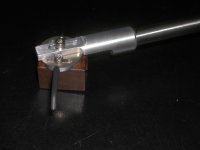
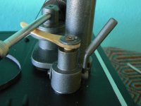
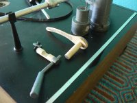
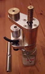
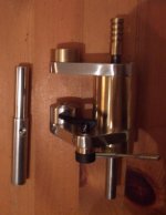
The pictures pretty much tell the whole story of the lift construction. The notch in the horizontal dowel makes it a cam. The vertical dowel with the lift arm attached rides the cam. It's lubed with candle wax. Gravity does the work. The final fitting between the plinth and the tonearm is the hard part because of all the geometry involved and you'll have customize that.
Jeff,
I'm seriously impressed with the amount of thought and work you've invested in your project. If you're building a roof, you can use a framing square and rafter calculation tables or you can do it 'farmer style,' which is where you hold a piece of material in place, eyeball it, and keep cutting until it fits. It's pretty obvious which technique I used.
I got distracted by the arm porn you posted 11/1 or thereabouts and missed the thread pages where you discussed details. I'll check them out.
I have a Thorens and an Empire, which are good candidates for a Schroeder clone upgrade. I can't do much metal work, but I have some interesting hardwood hanging around. I can do rectangular more accurately than round so I think I'll do something architectural along the lines of FLW's 'Falling Waters.' Maybe a whole table in that style.
In the meantime, the spousal obsession toleration level is dropping quickly so I'll just spend some time listening.
Bins Paul,
The pictures pretty much tell the whole story of the lift construction. The notch in the horizontal dowel makes it a cam. The vertical dowel with the lift arm attached rides the cam. It's lubed with candle wax. Gravity does the work. The final fitting between the plinth and the tonearm is the hard part because of all the geometry involved and you'll have customize that.
Jeff,
I'm seriously impressed with the amount of thought and work you've invested in your project. If you're building a roof, you can use a framing square and rafter calculation tables or you can do it 'farmer style,' which is where you hold a piece of material in place, eyeball it, and keep cutting until it fits. It's pretty obvious which technique I used.
I got distracted by the arm porn you posted 11/1 or thereabouts and missed the thread pages where you discussed details. I'll check them out.
I have a Thorens and an Empire, which are good candidates for a Schroeder clone upgrade. I can't do much metal work, but I have some interesting hardwood hanging around. I can do rectangular more accurately than round so I think I'll do something architectural along the lines of FLW's 'Falling Waters.' Maybe a whole table in that style.
In the meantime, the spousal obsession toleration level is dropping quickly so I'll just spend some time listening.
Attachments
Hello JD,
Got my first bundle of the tonearm metals parts today - Top brass plate, bottom brass plate, Aluminium section for the tonearm tube and Bottom magnet holder. I will post the images once I am back at home.
What is the status of your implementation ? How is it progressing ?
Best regards,
Bins.
Got my first bundle of the tonearm metals parts today - Top brass plate, bottom brass plate, Aluminium section for the tonearm tube and Bottom magnet holder. I will post the images once I am back at home.
What is the status of your implementation ? How is it progressing ?
Best regards,
Bins.
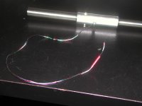
What a bloody tedious, stressfull task this was....but well worth the effort.
You have to have a very deliberate, and at the same time very light and with a gentle touch to quad braid 33 ga. wire without crimping it and a strong mental absolute focus not to lose the order of the braiding sequence and not to braid them too tight or too loose. Then fishing the bundle through a .1" hole and a right angle bend after the 10" of armtube. When you do this you must have the patience of ten saints. Wire is VanDenHul MCS150 silver....good stuff to work with considering....
No wonder specialist get the big bucks for this job!
Jeff
Attachments
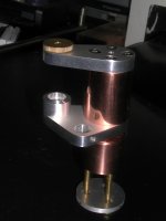
String attachment point
Hi, just started building a schroeder type arm, i have almost completed the base with micrometer thread for VTA adjustment, also planing a similar micrometer thread for adjusting the magnet spacing, still working on this part.
Magnets are 8mm X 5mm N42, i have drilled the arm stub and lower magnet carrier slightly deeper to allow for the addition of thin iron pole pieces, should these be needed.
After reading and re reading many posts, i am still more than a little confused as to the best position, height wise, to attach the suspension string to the arm.
Just above the upper magnet?, or higher up towards the top of the arm?
Are pole pieces really neccessary?
Thanks.
Attachments
Hello JD,
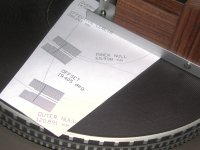
Can you post your home made protractor and alignment template in a printable format, so that I can use the same for my project ?
Best regards,
Bins.
Can you post your home made protractor and alignment template in a printable format, so that I can use the same for my project ?
Best regards,
Bins.
Hello JD,
Can you post your home made protractor and alignment template in a printable format, so that I can use the same for my project ?
Best regards,
Bins.
Sorry.... can't post what you're asking for. I built the protractor ad-hoc with material I had on hand and have no drawings... but it's very very simple.
Also, my guide was laid out in autocad using numbers generated from the eXcel spreadsheet at the bottom of this link:
Free Stuff
You plug in YOUR SPECIFIC length and it generates numbers and angles. Use those number to draw the geometry of the alignment needed.
Here's another resource that will let you print out an aligngment template.. Just click on:
Custom arc template generator for phono cartridge alignment (also prints strobe disks) to download the program.
Here's the link to the web page:
http://www.conradhoffman.com/chsw.htm
JD
Last edited:
My 8 year old digital camera just finished it's service life and my new replacement won't arrive till next Monday....
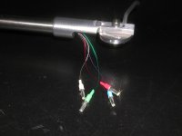
Anyways.... the arm is fully mounted. I put a fine woven silk cover sheath on the tonearm wires and soldered up the Lemo connectors for the junction box to RCA's... a bit of fiddliness under the magnifying lens ultra fine tip soldering, but the Van Den Hul MCS150 is nice to work with as the colored lacquer acts as a flux, unlike the Cardas that you have to burn it off first to get a good metal exposed solder joint.
I've also installed the cartridge (Benz Ruby 3) and set the alignment, VTA, and VTF. A note.... I measured VTF at the outer most groove and the inner most groove... I got no variation... holds at a rock steady 1.9 grams across the record.
One last thing I want to do before I put the deck / arm in my system is to put some damping fluid in the armtube support string well. I have some Silicone fluid of a very high viscosity (50,000 wt.) that I'll use (unless I hear otherwise in the next few days from the Guru Schroeder himself). The damping fluid is actually for a radio controlled car gearbox differentials. It's pure Dow Corning, clear, and very thick. Others have used it as a replacement for the SME damping fluid and other arms as well. Without the fluid, there is just a bit of side to side wobblyness and if the top and bottom magnets are too close, there is a tendency for the armtube to stay to one side or the other. The Counterweight needs to be set "just so" so the arm remains balanced at the fulcrum. I may try other counterwieght configurations later... instead of the outrigger that I'm using, I might try a single round dropped center counter weight.. might even put fine adjustment weights on both (either) sides to really fine tune the side to side balance.....
Jeff Davison
Last edited:
binspaul...
lots of protractors out there. Even custom ones can be done, as pointed out. It all depends on the tonearm geometry and the "style" of alignment that you desire. PM me if you are having problems.
Jeffrey (if I may call you that), your arm (well the first few pictures, so assume the rest is as good or better), looks great. Good craftsmanship.
All who have built this or are interested should thank Frank Schröder (berlinta) for the design and help he has provided to DIY (as have many others including Nelson Pass, etc in other areas of design) folks. 🙂
Last edited:
Hi Stew,
Nice to see you on this thread. Sure, I will contact you once my arm parts are ready.
Best regards,
Bins.
Nice to see you on this thread. Sure, I will contact you once my arm parts are ready.
Best regards,
Bins.
Hi JD,
1. How is the torsion element attached to the top magnet ?
2. Where is the pivot point located ? How do you manage to keep the thread at the absolute center of the magnet hole ?
3. What is the thread length you opted for ? (Any calculations for this)
Best regards,
Bins.
1. How is the torsion element attached to the top magnet ?
2. Where is the pivot point located ? How do you manage to keep the thread at the absolute center of the magnet hole ?
3. What is the thread length you opted for ? (Any calculations for this)
Best regards,
Bins.
Hi JD,
1. How is the torsion element attached to the top magnet ?
2. Where is the pivot point located ? How do you manage to keep the thread at the absolute center of the magnet hole ?
3. What is the thread length you opted for ? (Any calculations for this)
Best regards,
Bins.
#1 see post #241 and forward
#2 see post #241 and forward
#3 what ever arm/body configuration you come up with, what you need is to span the range of adjustment you want to build in. from 0 (zero) clearance to what the maximum you want taking into account the location of the upper drilled grub screw distance to the pivot... this is something you need to determine with your design... there is no formula or equations...it's all an your own determination. Draw it on paper or on computer for a close approximation then when you've built YOUR arm (everyones DIY is different in some degree to everyone elses) see if it is what you need, if not, keep trying till you've settled on YOUR optimum length...I believe this is what is called "trial and error".
JD
Last edited:
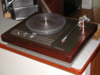
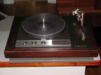
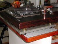
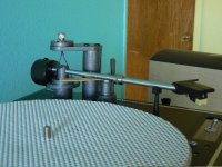
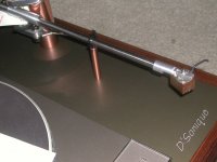
Bumping this up with a couple of pics of the completed and mounted arm.
I still can't put this in my system as I have no room on my component rack. I should have the new rack finished this upcoming weekend. The Garrard Plinth is a large and heavy beasty.
So far so good. Side to side balance still a bit sensitive to get the "sweet spot" with the outrigger to keep the magnet faces parallel to each other. The outrigger has no fine tuning. I got some brass in and I'll be fabricating a counterweight with small adjustable weights either side to make this task easier.
The weight will be a "Drop Center" and the small adjustable weights will be the "out-riggers"...or I may just mimick Herr Schroeder's design and cross bore and thread a hole across the bottom of the counterweight and use a couple of large inset set screws internal to the bore for the side-to-side balance fine tune.
JD
An externally hosted image should be here but it was not working when we last tested it.
An externally hosted image should be here but it was not working when we last tested it.
- Home
- Source & Line
- Analogue Source
- DIY Schroeder Tonearm?