Yes, so is mine.
😎
Well a 100uv noise amp can be considered as slightly more noisy than a 20uV noise amp. That is mesurable. Isn't it ? And using driver with more than 103db spl, you can here a small zzzzz from the F3, but not from the F2. But of course with a 90db spl driver....
I used two resistors to reduce the noise. I would love to see a F3 of J2 as silent as the F2 or F1.... I'm one of those PASS "adicts" who look forward to simple design, low power, low noise FirstWatt elegant philosophy
http://www.diyaudio.com/forums/images/smilies/cool.gif
Btw I've always wondered what in the design makes an amps ""noisier" than another
The F1 and F2 did not share a power supply ground. What
you are hearing is a ground loop between the two input
grounds.
😎
you are hearing is a ground loop between the two input
grounds.
😎
I would like to be able to make my factory Aleph 30 as silent as the J2 was in my system. The J2 rejects all ground noise. It's scary how silent that thing is.
Did you compare also the sonics? Just recently I read more about the aleph 30 🙂
Well a 100uv noise amp can be considered as slightly more noisy than a 20uV noise amp. That is mesurable. Isn't it ? And using driver with more than 103db spl, you can here a small zzzzz from the F3, but not from the F2. But of course with a 90db spl driver....
I used two resistors to reduce the noise. I would love to see a F3 of J2 as silent as the F2 or F1.... I'm one of those PASS "adicts" who look forward to simple design, low power, low noise FirstWatt elegant philosophy
I have my Hemps FR (94,5dB drivers) connected directly to the F3, no passive filters, I didnt measure with an instrument but with my ears (close to the speakers as they can be), and nada total silence.
I'll try later next year with more efficient drivers (my new project), around 100dB. It is obviously my goal that the amps are dead silent to my ear. I have an upgrade plan for the PSU of my F3 in case it'll be needed 🙂
Last edited:
I have had a slight bzzz with the F5 when input cables were plugged in only. Suggesting a ground loop.
The curing was a second transformer. Separate PSUs.
The curing was a second transformer. Separate PSUs.
Did you compare also the sonics? Just recently I read more about the aleph 30 🙂
Of course I did 🙂 They both sound wonderful of course. But to my ears and in a horn based system the Aleph 30 was a better match. The J2 wasn't even fully broken so take my opinion as nothing more than that. Oh well, while in Japan I'm hoping to hear the Feastrex first hand and if a pair of them follow me home then the J2 may again too...
F3, F1/2 ground loop?
The mystery thickens for the ignorant chap I'm, eh eh. Here is how it is set up:
Four way speakers, horn based (fostex [fostice 😎] drivers),
F1 is used for the bass (lack a bit of power, but alas, but rock bottom bass),
F3 for low (650hz - 1250 hz) medium, the driver is 106db spl,
F3 for high (1250hz - 4800hz) medium (103db spl also)
F2 for tweeter.
If i shortcut the input of the F3 and connect it alone to the low (or high medium) i can hear a light zzzz (not a klunk as per your article on class A 😎) which is audible when music is low.
If you explain me how i could address the ground loop between the two inputs (i guess input of F1 / F2) i might try anything. Bu how would that address the F3 noise is for me a mystery. If i can then remove the lpad filter directly attached to the driver driven by the F3 that would be 😎
Thanks
The F1 and F2 did not share a power supply ground. What you are hearing is a ground loop between the two input
grounds. 😎
The mystery thickens for the ignorant chap I'm, eh eh. Here is how it is set up:
Four way speakers, horn based (fostex [fostice 😎] drivers),
F1 is used for the bass (lack a bit of power, but alas, but rock bottom bass),
F3 for low (650hz - 1250 hz) medium, the driver is 106db spl,
F3 for high (1250hz - 4800hz) medium (103db spl also)
F2 for tweeter.
If i shortcut the input of the F3 and connect it alone to the low (or high medium) i can hear a light zzzz (not a klunk as per your article on class A 😎) which is audible when music is low.
If you explain me how i could address the ground loop between the two inputs (i guess input of F1 / F2) i might try anything. Bu how would that address the F3 noise is for me a mystery. If i can then remove the lpad filter directly attached to the driver driven by the F3 that would be 😎
Thanks
Last edited:
Power cords and the J2?
Those that have taken delivery of the J2 and Mr. Pass, if he cares to opine I would like to know if any have found any benefit to changing the power cord to something else?
Would the circuit itself tend to be insensitive to this kind of thing?
My curiosity has got the best of me, again.
Also, what size is the IEC socket? If anyone knows.
My experience is that it is insensitive. Also, don't
underestimate the quality of the power cord provided - it
is the same one we provide with X600.5's and such.
As to the socket, if you are referring to the IEC amperage
rating of the inlet, it is 15 amps.
😎
underestimate the quality of the power cord provided - it
is the same one we provide with X600.5's and such.
As to the socket, if you are referring to the IEC amperage
rating of the inlet, it is 15 amps.
😎
i can hear a light zzzz
"zzzz" to me would indicate not white noise but noise from the rectifier / transformer / PS (pulsed at 100/120 Hz), coming in either directly or via RF coupling. Just an idea, and you might be able to cure PS noise interference.
Light noise (with 106db spl driver) and the F3
Could you say more on how would you cure PS noise for a non expert ?
THanks
"zzzz" to me would indicate not white noise but noise from the rectifier / transformer / PS (pulsed at 100/120 Hz), coming in either directly or via RF coupling. Just an idea, and you might be able to cure PS noise interference.
Could you say more on how would you cure PS noise for a non expert ?
THanks
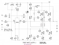
The simplified schematic of J2 what I suppose to be.
Here is the simplified schematic of Firstwatt J2 that published in the owner's manual of J2.
It says the output stage current source is no longer an "Aleph" current source, but a version of the classic "Mu Follower".
But the simplified schematic of Firstwatt J2 shown just a basic circuit of SRPP(Shunt Regulate Push-Pull).
Since it claimed to be a Mu Follower,
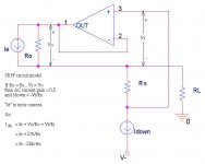
I suppose the simplified schematic of Firstwatt J2 should be just like this.
At first, I guest the regulator IC in the schematic is TL431.
Then the voltage drop of those two resistors will be 2.5V, it seems too high.
So, I guest the regulator IC in the schematic is LM385.
But, if it followed the spirit of "Simple is the best",
It maybe just a BJT MPSA18.
Here is the simplified schematic of Firstwatt J2 that published in the owner's manual of J2.
An externally hosted image should be here but it was not working when we last tested it.
It says the output stage current source is no longer an "Aleph" current source, but a version of the classic "Mu Follower".
But the simplified schematic of Firstwatt J2 shown just a basic circuit of SRPP(Shunt Regulate Push-Pull).
Since it claimed to be a Mu Follower,
I suppose the simplified schematic of Firstwatt J2 should be just like this.
An externally hosted image should be here but it was not working when we last tested it.
At first, I guest the regulator IC in the schematic is TL431.
Then the voltage drop of those two resistors will be 2.5V, it seems too high.
So, I guest the regulator IC in the schematic is LM385.
But, if it followed the spirit of "Simple is the best",
It maybe just a BJT MPSA18.
It is the lower half that drives - antiphase- the upper one.The voltage developped across the lower resistor only has to be taken into account for modulating the voltage source.
Seems to me.
Seems to me.
Last edited:
Could you say more on how would you cure PS noise for a non expert ?
I do not claim to be an expert but here it goes … Power supplies create switching noise because the stored charge of the rectifier diodes and the transformer’s leakage inductance form a resonant circuit that resonates each time the diodes stop conducting. This is high frequency noise pulsed at twice the frequency of the AC line (for bridged rectifiers) and is what you hear as buzzing.
This switching noise inside the power supply cannot be completely eliminated so you must stop it from coupling into the amplifier circuit, both directly via the DC voltage and indirectly via coupling of its electromangnetic fields into your amplifier.
Direct coupling will be reduced by proper filtering such as CRC or CLC filter and the cap multiplier of the F3 but since you have such sensitive speakers you may actually try to add another RC or LC filter step. Then again, looking at the 100 µVolt noise figure of the stock F3 my assumption is that this is mainly (“white ?”) noise of the amplifier circuitry itself and not causing the buzzing. With my 104 dB speakers and an amplifier that on paper has 35 µV noise I do not hear anything, ear on grille, but 100 µV are another 7 or 8 db so maybe I am just below the threshold.
Indirect RF coupling will be minimized by proper layout of the whole amplifier so this depends very much on how you physically construct it. The transformer, the mains and transformer leads, the rectifier diodes, and the first set of capacitors (connecting to the diodes) must be considered “dirty” and radiating RF noise. Keep them as far away from the active circuit and all signal carrying wires as you can, an outboard PS would be ideal (though it may not be needed), additional shilding may also help. Minimise the loop sizes of all leads inside the power supply, i.e. place transformer, first caps, and all diodes close together, keep wires very short and twist them together, etc. The same principals apply to signal wires and circuit.
Lastly, and AFTER you have done all the above you can also try to reduce the RF itself. Placing a cap of say 100 nF across the transformer secondaries reduces the resonant frequency and the ability to couple into other circuitry (radiation / pickup reduces by -6db per octave). Adding a snubber circuit damps the ringing further. A fuller explanation can be found in Jim Hagerman’s article on snubbers (should be on his WEB page). Fast, slow recovery or shottky diodes have lower noise than most standard rectifiers. All in all there are lots of littly details to look at and this forum alone is full of information, so do some more search.
Hope this helps
It is the lower half that drives - antiphase- the upper one.The voltage developped across the lower resistor only has to be taken into account for modulating the voltage source.
Seems to me.
Compare the SRPP(Mu Follower) and the "Aleph" current source,
They have the same conception with different methods.
Attachments

Thanks for your input.
I am now reading your thread with great interest.
(the images are restored at the end of the thread)
http://www.diyaudio.com/forums/pass-labs/37038-excellent-srpp-power-amp-mosfet.html
I am now reading your thread with great interest.
(the images are restored at the end of the thread)
http://www.diyaudio.com/forums/pass-labs/37038-excellent-srpp-power-amp-mosfet.html
Thanks for your input.
I am now reading your thread with great interest.
(the images are restored at the end of the thread)
http://www.diyaudio.com/forums/pass-labs/37038-excellent-srpp-power-amp-mosfet.html
That's a thread 5 years ago.
Mr. Pass has the invention patent of his Active current source.
But I think no one can claim the SRPP or Mu Follower as an invention patent now.😎
Last edited:
When looking closer, it seems that your enhanced Mosfet SRPP is very close to the aleph, which was anterior, the main difference being the sensing resistor position.
Or i missed something?
Or i missed something?
The concept of SRPP is long long ago, and of cause my enhanced Mosfet SRPP is later than Mr. Pass's Active Current Source.When looking closer, it seems that your enhanced Mosfet SRPP is very close to the aleph, which was anterior, the main difference being the sensing resistor position.
Or i missed something?
The difference?
The Active Current Source has positive feedback (bootstrap,regenerate) obviously, the SRPP dosen't.
That a difference.
The Active Current Source of Mr. Pass separates AC and DC siginals.
If you analyze the low frequence response of the Aleph 5 Amp and its Active Current Source, you will find the low frequence limit of the Aleph 5 Amp is much lower than its Active Current Source's.
My SRPP doesn't separate AC and DC siginals.
That's another difference.
If I enhance the SRPP circuit extremely, I may choose 0.6V Open Collector Shunt Voltage Reference TS4436 to replace MPSA18.
Last edited:
- Home
- Amplifiers
- Pass Labs
- FirstWatt J2