Sorry to hear about your misfortunes, ElFishi and SimonKit
Thanks, I hope to learn from it. Anyway, I upgraded 2 other amps (a gainclone and the Trends Audio TA-10) this weekend with the Mcaps from Mundorf I tried on this Sure Electronics amp because I like them very much! Next time I will be more careful with the PCB.

Is there a Sure board hierarchy of suggested mods?
I would think that replacing the input caps to something like the Dayton poly foil caps is a good start for maximum improvement in sound quality for the least amount of work/money. I've gone through all the posts and have the glazed eyes to show for it. Is there anyone out there who might be more organized or knowledegable than me (I think: "yes"), someone who's willing to make a list of what might be the best upgrades for most DIYers? I'm thinking something along the lines of:
The above list is just an example, surely someone has a better idea . . .
Thanks!
I would think that replacing the input caps to something like the Dayton poly foil caps is a good start for maximum improvement in sound quality for the least amount of work/money. I've gone through all the posts and have the glazed eyes to show for it. Is there anyone out there who might be more organized or knowledegable than me (I think: "yes"), someone who's willing to make a list of what might be the best upgrades for most DIYers? I'm thinking something along the lines of:
I. Must Do's: swap out input caps, upgrade signal path resistors, etc.
II. Worth Doing for Better Sound: swap out stock inductors for toroids, etc.
III. Might Be Worth Doing: battery PS
II. Worth Doing for Better Sound: swap out stock inductors for toroids, etc.
III. Might Be Worth Doing: battery PS
The above list is just an example, surely someone has a better idea . . .
Thanks!
Last edited:
Volume Control, Bypassing It
If I want to just use the Sure board as an amp, and do not want to have a volume pot connected, is there a place on the board I should short out or leave open? I'd prefer to have my preamp control the volume and to have the amp not have a pot controlling resistance on the input.
If I want to just use the Sure board as an amp, and do not want to have a volume pot connected, is there a place on the board I should short out or leave open? I'd prefer to have my preamp control the volume and to have the amp not have a pot controlling resistance on the input.
Last edited:
Anybody know where the 2.5V connection is on this board? I want to try a capacitorless connection from my transformer output DAC as Panomaniac describes in the transformer coupled DAC thread.
If I want to just use the Sure board as an amp, and do not want to have a volume pot connected, is there a place on the board I should short out or leave open? I'd prefer to have my preamp control the volume and to have the amp not have a pot controlling resistance on the input.
No problem. I used it this way combined connected to my passive preamp from Antique Sound Lab http://www.uhfmag.com/Issue62/aslpassive.html
There is nothing you have to change on the board ... however if you have an active pre-amp I would set the gain on the board of the Sure amp to the lowest setting with the dipswitches.
I. Must Do's: swap out input caps, upgrade signal path resistors, etc.
II. Worth Doing for Better Sound: swap out stock inductors for toroids, etc.
III. Might Be Worth Doing: battery PS
my take:
I.
- Input caps
- tank caps (and thus depending on your PSU also a soft start)
II.
- Input and feedback resistors
III.
- output filter incl. toroids
- voltage regulator
- re-route power rails on PCB and remove diodes (amp likes every bit of voltage)
IV. Might not be worth doing
- re-wiring pins 24 on both TP2050s to 21,22 (Vdd) instead of gnd
- exchange C22&27 for 470pF as per the TC2000 data sheet
Anybody know where the 2.5V connection is on this board? I want to try a capacitorless connection from my transformer output DAC as Panomaniac describes in the transformer coupled DAC thread.
There is no 2.5V connection. It is the virtual ground of the input opamp of the TC2000 fed with 5V supply voltage. Plus there are pots (R5&R26) to fine tune the 2.5V such that there is no output offset voltage.
There are people though who run tripath based amps capless:
http://www.diyaudio.com/forums/showthread.php?p=1201831
my take:
I.
- Input caps
- tank caps (and thus depending on your PSU also a soft start)
II.
- Input and feedback resistors
III.
- output filter incl. toroids
- voltage regulator
- re-route power rails on PCB and remove diodes (amp likes every bit of voltage)
IV. Might not be worth doing
- re-wiring pins 24 on both TP2050s to 21,22 (Vdd) instead of gnd
- exchange C22&27 for 470pF as per the TC2000 data sheet
A very good list, ElFishi. I think I'd add the Zobel filter to group I or II, more for safety than sound quality.
-dr_vega
Thanks for a useful list, ElFishi! And thanks, SimonKit, I'll try the dip switches on the lower settings and experiment a bit. I'll be using a Yaquin phono/line preamp.
Thanks to dr_vega and audio1st for a bunch of useful insights, and to all the others who've contributed.
Thanks to dr_vega and audio1st for a bunch of useful insights, and to all the others who've contributed.
There is no 2.5V connection. It is the virtual ground of the input opamp of the TC2000 fed with 5V supply voltage. Plus there are pots (R5&R26) to fine tune the 2.5V such that there is no output offset voltage.
There are people though who run tripath based amps capless:
http://www.diyaudio.com/forums/showthread.php?p=1201831
well, all tripath chips do have a 2.5V ref pin, although like most the Sure doesn't really do anything with it. I'm also looking at how to do a direct-coupled input, and my thinking at the moment is that simply using an adjustable potential divider on the Vocm pin of the instrumentation amp is probably as good as anything else. Actually tapping in to the 2.5V reference directly would probably involve soldering directly to the tc2000, which seems to be a bit risky.
my specs
I have some spare time while I wait for the new sure board to replace the one I scorched. So I completed the list of mods and things around the board I did. Maybe you find that interesting.
PSU Mean Well 24/145:
- cranked up to almost 30V
- 0.47uF MKS btn GND and COM
Sure board:
- changed PCB traces per audio1st suggestions (http://www.diyaudio.com/forums/showpost.php?p=1855510&postcount=145)
- removed D1,2
- added 0.1uF parallel to C6 from the underside of the board
- exchanged C22&27 for 470pF as per the TC2000 data sheet
- re-wired pins 24 on both TP2050s to 21,22 (Vdd) instead of gnd
- removed tank caps from rails and replaced with 2 x 2 Panasonic FM 1800uF/35V on the rails
- replaced C3 with same type Pana FC
- added 0.1uF/100V MKP4 parallel to C3
- replaced C4 with standard-middle-of-the-road cap 100uF/10V
- replaced R2 with 2 green low-current LEDs, V_F=2.0V
- replaced R3 with 470Ohm
- added diodes 1n4001 btn Vadj/Vout and Vin/Vout
- replaced output filter
- interrupted traces btn input RCA and screw terminal
- removed R11,27 and replaced with 22kOhm metal film connected btn old solder pad and screw terminal
- removed R4 to open loop over SignalGND, Earth and B1
- added modified Pass B1 buffer (http://www.passdiy.com/pdf/B1 Buffer Preamp.pdf, http://www.diyaudio.com/forums/showpost.php?p=1539729&postcount=1) to input
- 1nF/1000V MKP4 from speaker terminals to chassis
B1 specs
- R1 2.4 Ohm
- C1,2 2 x 3 x 3800uF/35V Panasonic FC
- C3 1uF MKP-10
- Cx00: 1uF MKP-10
- Cx01: 2.2uF MKP-10, directly linked to input resistor of sure board
- Rx05,x05: dropped
- 50k Vishay conductive plastic, log taper
- added 1N5401 to input of positive rail, bypassed by a 1k resistor for a controlled discharge of the caps (otherwise the sure amp makes an ugly noise when going down)
Soft Start/ Mute On Off Circuit
- 24V/0.4W relay 8A 2CO contacts (tyco RT424024)
- 2 white LEDs (~6V drop) in line with coil
- 47 Ohm/ 5W resistor to fill the tank caps up to operating voltage for the relay
- 1N4148 parallel to relay coil
- 0.39 Ohm/5W resistor to filter the power supply and to sense the current
- TL081 as comparator (TL081 can work in high-side applications)
- 2 x 10k voltage divider to drive a
- BS170 that mutes the amp when power is switched off and the tank caps unload via the SMPS and the current sensing resistor
- 100uF btn MUTE and GND to keep the amp mute a little longer
- 3 x 3300uF/35V Yageo SY tank caps
- 1800uF/35V Panasonic FM next to output (close to amp power input)
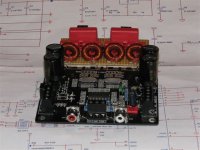
piccie of the board w/ toroids and schematic of the "mute on off" circuit attached
I have some spare time while I wait for the new sure board to replace the one I scorched. So I completed the list of mods and things around the board I did. Maybe you find that interesting.
PSU Mean Well 24/145:
- cranked up to almost 30V
- 0.47uF MKS btn GND and COM
Sure board:
- changed PCB traces per audio1st suggestions (http://www.diyaudio.com/forums/showpost.php?p=1855510&postcount=145)
- removed D1,2
- added 0.1uF parallel to C6 from the underside of the board
- exchanged C22&27 for 470pF as per the TC2000 data sheet
- re-wired pins 24 on both TP2050s to 21,22 (Vdd) instead of gnd
- removed tank caps from rails and replaced with 2 x 2 Panasonic FM 1800uF/35V on the rails
- replaced C3 with same type Pana FC
- added 0.1uF/100V MKP4 parallel to C3
- replaced C4 with standard-middle-of-the-road cap 100uF/10V
- replaced R2 with 2 green low-current LEDs, V_F=2.0V
- replaced R3 with 470Ohm
- added diodes 1n4001 btn Vadj/Vout and Vin/Vout
- replaced output filter
- 12uH self-wound toroids: T68-2 with 46 windings of 0.6mm enameled wire, sets of 2 plain windings followed by 1 clove hitch to double up the wire layer on the inner perimeter of the toroid
- .47 uF/250V MKP4 as common mode capacitors
- .22uF/630V MKP4 (had those in the box) as differential mode capacitor
- .22uF/250V MKP4 as Zobel capacitor
- 10 Ohm/1W Metal Oxide as Zobel resistor
- interrupted traces btn input RCA and screw terminal
- removed R11,27 and replaced with 22kOhm metal film connected btn old solder pad and screw terminal
- removed R4 to open loop over SignalGND, Earth and B1
- added modified Pass B1 buffer (http://www.passdiy.com/pdf/B1 Buffer Preamp.pdf, http://www.diyaudio.com/forums/showpost.php?p=1539729&postcount=1) to input
- 1nF/1000V MKP4 from speaker terminals to chassis
B1 specs
- R1 2.4 Ohm
- C1,2 2 x 3 x 3800uF/35V Panasonic FC
- C3 1uF MKP-10
- Cx00: 1uF MKP-10
- Cx01: 2.2uF MKP-10, directly linked to input resistor of sure board
- Rx05,x05: dropped
- 50k Vishay conductive plastic, log taper
- added 1N5401 to input of positive rail, bypassed by a 1k resistor for a controlled discharge of the caps (otherwise the sure amp makes an ugly noise when going down)
Soft Start/ Mute On Off Circuit
- 24V/0.4W relay 8A 2CO contacts (tyco RT424024)
- 2 white LEDs (~6V drop) in line with coil
- 47 Ohm/ 5W resistor to fill the tank caps up to operating voltage for the relay
- 1N4148 parallel to relay coil
- 0.39 Ohm/5W resistor to filter the power supply and to sense the current
- TL081 as comparator (TL081 can work in high-side applications)
- 2 x 10k voltage divider to drive a
- BS170 that mutes the amp when power is switched off and the tank caps unload via the SMPS and the current sensing resistor
- 100uF btn MUTE and GND to keep the amp mute a little longer
- 3 x 3300uF/35V Yageo SY tank caps
- 1800uF/35V Panasonic FM next to output (close to amp power input)
piccie of the board w/ toroids and schematic of the "mute on off" circuit attached
Attachments
Then I started it up and heard a high peeping noise.
You're TC2000 is gone, I got 2xTC2000 from Sure for 10$ including shipping.
I had the same on my board after I had replaced the 2 broken TP2050.
Hi all i have a 41hz amp 6b i think its great but need a bit more power. I have seen the sure 2x100 watt and wondered how thay sound against the 41hz amps
Hi all i have a 41hz amp 6b i think its great but need a bit more power. I have seen the sure 2x100 watt and wondered how thay sound against the 41hz amps
The 41hz amps w/ the TK2050 chipsets come w/ higher quality components I believe and probably sound better.
HOWEVER, you have to build them from scratch and even the 41hz website says that the Amp11 (and 4?) kits are not for beginners. The kits are also more expensive. Also, although people are very friendly and helpful at 41hz forum, it seems like there are always things that go wrong while building their amps and there is very little documentation for anything except the Amp6 and Amp9 amps.
Bottom line is if you are *very* skilled at soldering and like problem solving, including smd's then try 41hz kits. If not, then go w/ the sure board and then add modifications mentioned in this thread. MUCH easier. hope this helps.
Hi WUSHULIU i know what you mean on the price but the basic hole mounted kits are fairly easy i am not very good at electronics but managed not to blow the amp6 up the hardest part was how to wire the volume pot. So do you think the sure amps are as good if you mod them up
Hi WUSHULIU i know what you mean on the price but the basic hole mounted kits are fairly easy i am not very good at electronics but managed not to blow the amp6 up the hardest part was how to wire the volume pot. So do you think the sure amps are as good if you mod them up
Again, I would think the 41hz sounds better because of the higher quality components. So, all else being equal I would go w/ the 41hz (the Amp5?). But don't say I didn't warn you about putting them together😀
My latest mods!
I went shopping in a local electronics haven, but could not find the inductors that I wanted (11uF with Carbonyl-E toroidal core). And I was not also confident of being able to remove the existing inductors without damaging the board. So I decided to keep the existing inductors meaning I got stuck with the cut-off frequency of 41Khz (at my speaker's load of 8 ohm).
I decided to try the "simpler design" I mentioned in my previous post so I bought some WIMA MKS2 as I was not able to find MKP2 or FKP2. The differential caps are 0.33uF and the shunt caps are 0.068uF. I also added zobel caps rated at 0.47uF along with 10 Ohm 1W 1% metal resistors.
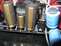
While at it, I also thought I would try replacing those tank caps. I visited a dozen shops in search for Panasonic FC or ELNA SILMIC remembering their mentioning in the forum, but none of them stocked the caps to my disappointment. So I ended up buying two 1000uF Rubycons. But then when I was about to head home, I found a small shop selling ELNA SILMIC II after more than two hours of walking and searching! I bought 4 of 470uF and 2 of 100 uF because they were only the SILMICs she had in her shop! Also in my shopping bag were an ALPS 50Kohm potentiometer and a 4 pole 3 position rotary switch.
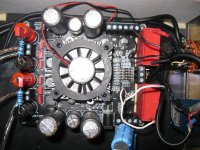
After half a day of tinkering around filled with anxiety and frustration especially with the wiring, I finally made it! You can see my shoddy soldering and wiring work in the pictures attached. 😱
So how does it sound after the mods? Well, one thing I can say with certainty is that bass has become A LOT more powerful yet controlled. I can hear more clearly when the bass comes and goes. However, I am not sure if it has lost a bit of clarity and sharpness. Initially, I felt it sounded less sparkling as it used to, but then more I listen to it, I am beginning to like the new sound in that it sounds a bit more balanced and natural. I just wonder how much sound I have lost due to my shoddy wiring and soldering. 😱
I went shopping in a local electronics haven, but could not find the inductors that I wanted (11uF with Carbonyl-E toroidal core). And I was not also confident of being able to remove the existing inductors without damaging the board. So I decided to keep the existing inductors meaning I got stuck with the cut-off frequency of 41Khz (at my speaker's load of 8 ohm).
I decided to try the "simpler design" I mentioned in my previous post so I bought some WIMA MKS2 as I was not able to find MKP2 or FKP2. The differential caps are 0.33uF and the shunt caps are 0.068uF. I also added zobel caps rated at 0.47uF along with 10 Ohm 1W 1% metal resistors.
While at it, I also thought I would try replacing those tank caps. I visited a dozen shops in search for Panasonic FC or ELNA SILMIC remembering their mentioning in the forum, but none of them stocked the caps to my disappointment. So I ended up buying two 1000uF Rubycons. But then when I was about to head home, I found a small shop selling ELNA SILMIC II after more than two hours of walking and searching! I bought 4 of 470uF and 2 of 100 uF because they were only the SILMICs she had in her shop! Also in my shopping bag were an ALPS 50Kohm potentiometer and a 4 pole 3 position rotary switch.
After half a day of tinkering around filled with anxiety and frustration especially with the wiring, I finally made it! You can see my shoddy soldering and wiring work in the pictures attached. 😱
So how does it sound after the mods? Well, one thing I can say with certainty is that bass has become A LOT more powerful yet controlled. I can hear more clearly when the bass comes and goes. However, I am not sure if it has lost a bit of clarity and sharpness. Initially, I felt it sounded less sparkling as it used to, but then more I listen to it, I am beginning to like the new sound in that it sounds a bit more balanced and natural. I just wonder how much sound I have lost due to my shoddy wiring and soldering. 😱
Attachments

- Status
- Not open for further replies.
- Home
- Amplifiers
- Class D
- Sure Electronics New Tripath Board tc2000+tp2050