A question: do I need something additional when using Mean Well SP-200-24. E.g. to protect the amp while starting up for the inrush current. I never used SMPS for an amplifier.
Depends on the size of the tank caps you use. Too much capacitance and the SMPS will trip when switched on. With post #513 I posted a simple soft start that uses the tank caps as "C" in an RC-circuit to slowly fill the caps. You can ignore the rhs of the schematic.
Depends on the size of the tank caps you use. Too much capacitance and the SMPS will trip when switched on. With post #513 I posted a simple soft start that uses the tank caps as "C" in an RC-circuit to slowly fill the caps. You can ignore the rhs of the schematic.
OK thanks!
Has anybody experiemented with a fully passive soft-start circuit? I am thinking it must be possible to make a passive circuit that mutes the amp at turn-on and then slowly demutes it. I would really like to get rid of the ugly turn-on thump I have, but making an active solution with relays seems overkill to me. Any ideas/experience out there?
/U.
/U.
Has anybody experiemented with a fully passive soft-start circuit? I am thinking it must be possible to make a passive circuit that mutes the amp at turn-on and then slowly demutes it. I would really like to get rid of the ugly turn-on thump I have, but making an active solution with relays seems overkill to me. Any ideas/experience out there?
/U.
Simplest is probably a three position switch: Off; soft start; full power.
To turn it on, switch to soft start, wait 5 seconds, switch it to full power.
-dr_vega
TP2050 pin 24?
What does this change?
.So I completed the list of mods and things around the board I did. Maybe you find that interesting.
- re-wired pins 24 on both TP2050s to 21,22 (Vdd) instead of gnd
What does this change?
.
What does this change?
Nuttin.
I did it b/c the TK2050 datasheet says
For parallel mode operation, the TK2050 can be configured as a single full bridge with double current capability by connecting the CONFIG pin to the Vdd pin of the TP2050.
Maybe I am being dense, but how would you enable the soft start mode?Simplest is probably a three position switch: Off; soft start; full power.
To turn it on, switch to soft start, wait 5 seconds, switch it to full power.
-dr_vega
/U.
Has anybody experiemented with a fully passive soft-start circuit?
Could a thermistor work for this purpose ?
http://bit.ly/4BuHe
Probably not. I was thinking more along the lines of a simple RC-based circuit to mute the amp when power is applied and then slowly unmute as the cap is charged, but I am not really sure how to make it work.
/U.
/U.
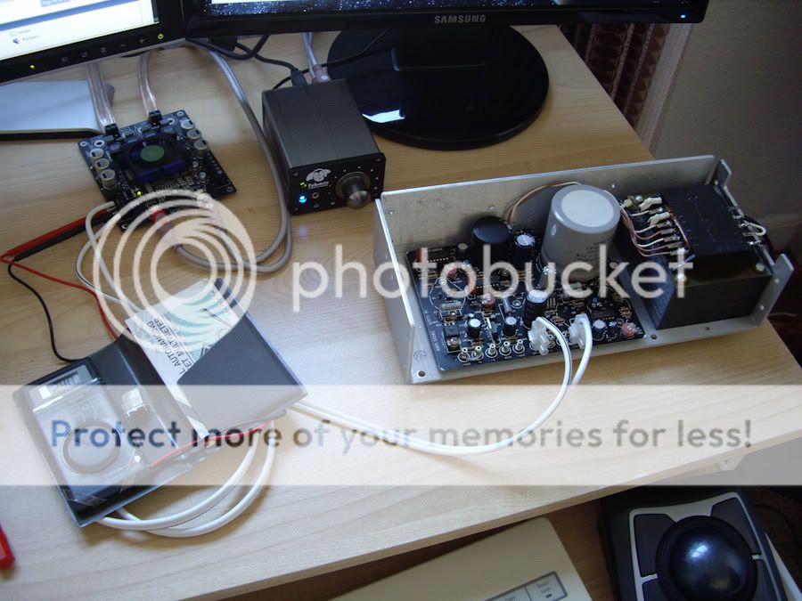
I got my board a few weeks back & have been using a 12v 2A SMPS brick from an external hard disk, but just this morning the UPS man came with the linear power supply I grabbed off eBay for £13 delivered.
It's a Power-One CP162-A, rated to push 24v @ 5A. Manual says you can adjust the output up to 29v @ 3A. It's a bit bigger than I was expecting...
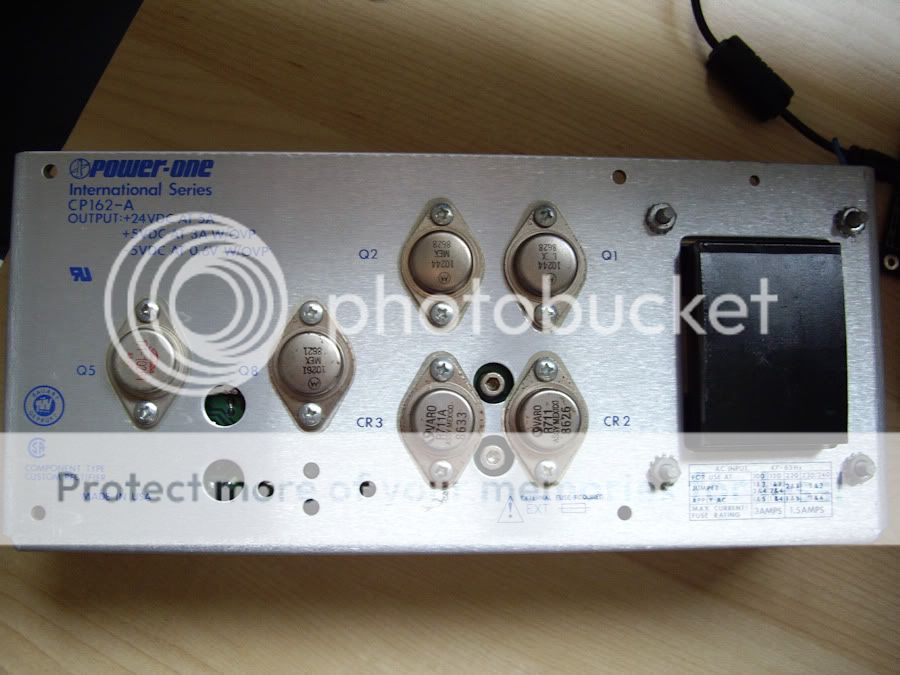
Haven't tested it yet as I'm not sure which output terminals I should use? It didn't come with a schematic & all I can find online is the data sheet for the range, which just tells you the ratings of each model. Anybody help me out? The output terminals are pictured beneath.
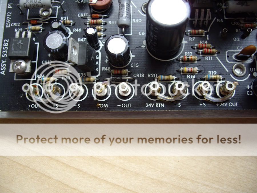
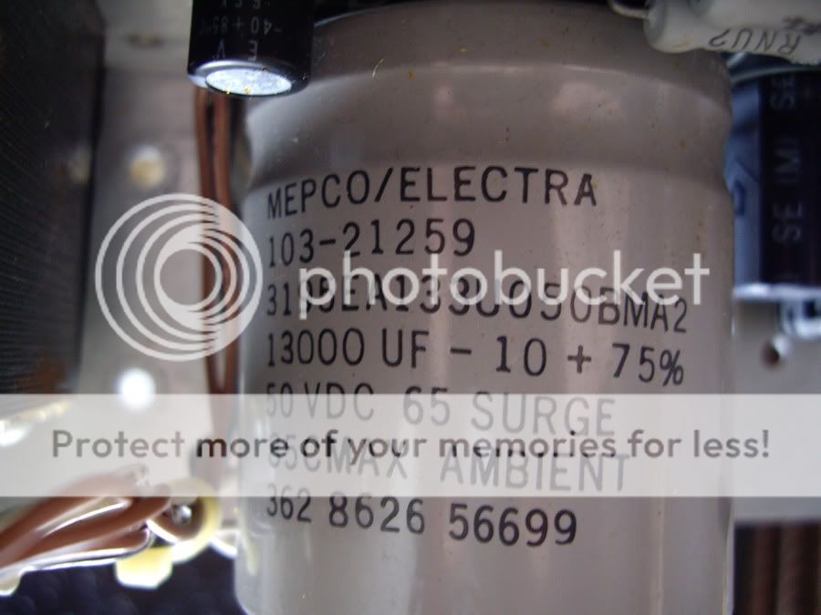
I'm guessing I use "+24V OUT" to connect to the amp's "VCC" & "24V RTN" to the amp's "GND"? But I'm not sure why some of the terminals are bridged, which is worrying me - I don't want to risk a 13000uF cap exploding & taking my head off!
It's a Power-One CP162-A, rated to push 24v @ 5A. Manual says you can adjust the output up to 29v @ 3A. It's a bit bigger than I was expecting...
Haven't tested it yet as I'm not sure which output terminals I should use? It didn't come with a schematic & all I can find online is the data sheet for the range, which just tells you the ratings of each model. Anybody help me out? The output terminals are pictured beneath.
I'm guessing I use "+24V OUT" to connect to the amp's "VCC" & "24V RTN" to the amp's "GND"? But I'm not sure why some of the terminals are bridged, which is worrying me - I don't want to risk a 13000uF cap exploding & taking my head off!
Has anybody experiemented with a fully passive soft-start circuit? I am thinking it must be possible to make a passive circuit that mutes the amp at turn-on and then slowly demutes it. I would really like to get rid of the ugly turn-on thump I have, but making an active solution with relays seems overkill to me. Any ideas/experience out there?
/U.
found that somewhere in the lepai thread
http://img188.imageshack.us/img188/2143/lepaipopsuppressor.jpg
plus, I never tried it, but the sure-board actually starts muted on power on by virtue of C20, R23 and R24.
So increasing C20 could do.
Maybe I am being dense, but how would you enable the soft start mode?
/U.
Not dense at all, it's a good question.
There isn't a soft start "mode." The soft start is just something to slow the flow of current from the power supply to the board. Usually this is a resistor of a few tens of ohms rated for the power it needs to handle.
So the "soft start" position on the power switch would put maybe a 20 ohm, 10 watt resistor in series between the power supply and the amp. The "on" position would by-pass the resistor and take the power directly to the board.
-dr_vega
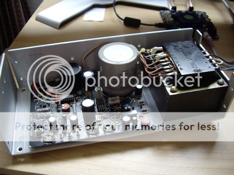
Got in touch with the eBay seller who sold me the power supply who was a lovely guy & explained that the S terminals are the remote sense inputs - but because the equipment it was powering was close by he just bridged them.
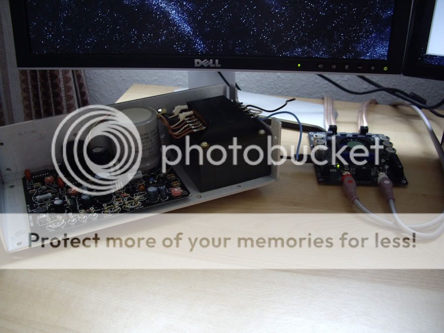
Got it up & running now & I can say that there is definitely an immediately audible improvement over the 12v SMPS brick I was using - treble in particular is gorgeous, I genuinely have never heard my speakers pick up some of the sparkles they are now!
Got it up & running now & I can say that there is definitely an immediately audible improvement over the 12v SMPS brick I was using - treble in particular is gorgeous, I genuinely have never heard my speakers pick up some of the sparkles they are now!
Fixed my dead channel
I installed the TC2000 that Sure was nice enough to send me but still had no sound from channel 2 although then there was at least now a normal turn on thump. Setting one of the gain switches to on restored the sound and allowed me to isolate the fault to a poor connection of R32. Resoldering it fixed the problem. Now I can continue with better comparisons of mods and power supplies as I have three working boards and two switching power supplies to go with my linear supply and batteries.
.I purchased 2 Sure amp boards when I ordered so as to be able to do A B comparisons of mods as I went but one amp never played the right channel
I installed the TC2000 that Sure was nice enough to send me but still had no sound from channel 2 although then there was at least now a normal turn on thump. Setting one of the gain switches to on restored the sound and allowed me to isolate the fault to a poor connection of R32. Resoldering it fixed the problem. Now I can continue with better comparisons of mods and power supplies as I have three working boards and two switching power supplies to go with my linear supply and batteries.
Hi everyone,
I am new to the site and I have just started reading into the world of DIYAUDIO. I first started by looking at the Sonic T-amps, but the 2x15w leaves something to be desired.
I am reasonably handy with my hands but I have little experience with electronics. I started looking into this new tripath board. At 2*100 (or even 2*40), this would be an improvement over the sonic.
My question is: I understand that sure-electronics sells the board and connectors. I am wondering where you guys buy your enclosures from and whether this would be a good diy for an entry level consumer? I know I can get a sonic amp for $40, but I want work on this myself.
Getting thousands of uF in film or foil capacitors is hard. It takes a lot of room and a lot of money. In the world I live in, it's not feasible, electrolytics are an evil necessity. I generally use Elna Silmics and I like them a lot, although Digikey only has them up to 35v. I also like Panasonic FM and FC, which I'll use on the TK2050 because I need 50v.
I've never tried bypassing electrolytics with film or PIO, but I might try it with the TK2050. I'm liking the Dayton foil caps so much as signal caps, I might try bypassing some storage caps with them.
My first upgrade signal caps on my first T-amp were Obligattos. I hated them. They sounded harsh to me even after 200 hours of break in. I felt the same about Solen Fast Caps. I liked the Dayton films better, but eventually went to paper in oil. So you can see that I like a more liquid sound, but still with plenty of detail.
Is there a long burn-in time for this amp? I've got it running w/ Silmics in the PS, Jantzen 3.3uf Crosscaps for the inputs, and 10uh toroids at the output. After 15hrs of listening, I like the midrange but the treble is fatiguing. I feel like it has to sound better than this for everyone to love Class-T's as much as they do (this is my first tripath amp).
Improvements from mods easier to hear with two amp boards to compare
Now having three working Sure 2X100 boards I went back through and verified the improvements of the various mods that I have tried. I must correct two of my earlier statements from an earlier trial I did with one Sure board vs. my TDA7250. This was an apples and orange comparison which made it harder to compare the before and after as I modded the Sure. Also helping to make the differences stand out more is the fact that the switch mode PSUs kill the sonics of an unregulated (I had to remove the regulator as it went into limit on start up and never would allow more than 6v.) and 20,00uf and bypassed filtered linear supply. I can't believe I fell in with the out dated hype and automatically assumed the linear supply would be better, never even trying switch mode until now. The switching supplies rock with better detail and micro dynamics. I'll get back to you on a comparison to the car batteries.
.
Without getting too long in writing of the specific changes to the sound by track number and time, now that I have two identical boards and switching power supplies, I can easily hear that removing the suppressor from the input connector brings an increase in see through clarity.
.
I also first tried the stock input cap against 1uf of Dayton foils. The Daytons make the original caps sound honky in the upper midrange and woolly and uncontrolled in the bass. The foils also bring another dose of fine detail. I forgot to try removing the little chip cap so that will have to wait for another day, along with some filter cap additions. Surface mount resistors generally sound better than through hole so I probably won't mess with those.
.
Sad news and a little tougher to deal with, the fan is indeed polluting the 5v as lifting the fan's wires in favor of an external battery supply brings another improvement in see through sound stage similar to the removal of the suppressor. I will buy some 5v fixed regulators, nothing fancy, to run off of the 32v rail to isolate the fan noise onto it's own supply. If I end up doing my own boards I will just leave room for a real heat sink.
.
running one channel each of two identical boards dual mono with their own supplies for separate right and left makes the sound wider and deeper, especially into the corners. Bass is a little tighter but surprisingly seems maybe a little less in absolute abundance? Is this more accurate to the recording? who knows. Not a negative. I would have thought more headroom in the power supplies would be louder bass. Still, all in all better sound from dual mono.
.
Now the second thing I was mistaken about in my earlier post and, some good news bad news. The new filter with 4uH air core coils and Dayton foil caps DESTROYS the stock output filter! Explosive dynamics! Crazy how the sound stage grew taller and bigger! Another big dose of see through detail and a blacker presentaion with better focus. Absolute no brainer except for...
The ultrasonic noise emission is noticeable in an AM radio tuned from 600 to 700kHz from up to 20 feet away. The pundits were right. Unshielded air cores in class D amps throw some nasty noise out into the universe. Maybe my foil coils will be a little better due to every winding laying perfectly on top of the other. Maybe I can come up with a usable shield. Maybe a big toroid will sound just as good.
.
Aside from the the question of the coil, I am now sold. Class D (T) can sound as good or better than a good class AB amp and be cheaper to build and use a fraction of the electricity. Good news for my 5 way digital cross project I have been dreaming about.
Last edited:
My question is: I understand that sure-electronics sells the board and connectors. I am wondering where you guys buy your enclosures from and whether this would be a good diy for an entry level consumer? I know I can get a sonic amp for $40, but I want work on this myself.
Well, I hadn't done any DIY of any sort before getting my Sure TK2050 board and I literally learned to solder for the first time on the board. You can see how new I am to this by reading some of my past posts which demonstrate my denseness and lack of skills. However, with great help from excellent people on this forum, I have successfully built a working amplifier and even managed to apply a few mods, which I feel have improved the sound quality quite a bit. Special thanks go to Audio1st, ElFishi and Dr.Vega and others for making it all possible!
I was thinking of buying a nice looking enclosures too but then I didn't want to spend too much on my first project, which I was not even sure how it would turn out. So I put together a simple enclosure out of acryl sheets and some wooden board I salvaged from here and there. Almost zero cost! 😀
Anyway, the best thing of all is that I have learned so much from the project! Of course, I don't think my modified Sure TK2050 will compete with high-end expensive gears, but I am hugely satisfied what I am hearing, especially considering the kind of money I spent on the whole project. If I can do it, I am very sure anyone can do it!
Sad news and a little tougher to deal with, the fan is indeed polluting the 5v as lifting the fan's wires in favor of an external battery supply brings another improvement in see through sound stage similar to the removal of the suppressor. I will buy some 5v fixed regulators, nothing fancy, to run off of the 32v rail to isolate the fan noise onto it's own supply. If I end up doing my own boards I will just leave room for a real heat sink.
Wouldn't it better to run the fan at its native 12V? I am running mine at 5V only because I don't have a 12V source.
Actually, I am wondering if it would be possible to integrate a 12V fan and a cool blue diode or two as part of ElFishi's soft start circuit. I wonder if the fan and the diodes would work as some form of delay. Or would it be a bad idea to share the same power source between the fan and the board?
Wouldn't it better to run the fan at its native 12V? I am running mine at 5V only because I don't have a 12V source.
QUOTE]
If you're going to put in a separate voltage regular for the fan, you can have any voltage you want.
The considerations, I think, are how much current will the fan draw and how loud will the noise it makes be. The higher the voltage, the faster the fan turns, therefore more current and more noise.
I'm using a tiny 12v fan running at 5v. It is a little bare blade (no housing) fan I glued directly onto the heatsink with some silicon glue. I think it cost me a buck and a half on ebay. It came from China.
I can barely detect the breeze the fan generates and it is completely silent. I didn't think there was any chance that it would cool the chips adequately.
Imagine my surprise that the heatsink with the fan barely gets warm to the touch. It used to get hot enough that it was uncomfortable to touch it.
It seems that you only have to move a little bit of air across the heatsink, just enough so the air isn't stagnent. You don't need anything approaching a breeze or a wind.
Based on sendler's observation, I'll probably put in a separate regular and caps for the fan, over near the power input, but I'll use 5volts.
-dr_vega
- Status
- Not open for further replies.
- Home
- Amplifiers
- Class D
- Sure Electronics New Tripath Board tc2000+tp2050