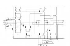
I found a schematic for the very highly regarded (as far as I can tell) zapfilter 2. I thought I would post it here in the hopes that someone can do somthing useful with it such as a PCB layout.
Click here for a very high resolution version.
I'm not aware of too many DIY discrete output filters... none at all in fact. So I hope this can be useful perhaps as insperation to design an even better one. I don't really have a good enough understanding of the circuit to do that or a PCB layout myself.
Click here for a very high resolution version.
An externally hosted image should be here but it was not working when we last tested it.
I'm not aware of too many DIY discrete output filters... none at all in fact. So I hope this can be useful perhaps as insperation to design an even better one. I don't really have a good enough understanding of the circuit to do that or a PCB layout myself.
I use quite a few of these for customer mods, they are very good when you get one that controls the dc offset well (+- 1-5mv), but it's a bit hit and miss, after sending a few back to LC Audio with this problem I eventually get good ones.
Gert the owner of LC Audio told me 4 months ago in the near future there will be a new Zapfilter MkIII that will address this issue and be better sounding as well, it's been 4 mths now and it is still not avalible.
Gert if you read this can you give us an update on the new MkIII?
Cheers George
Gert the owner of LC Audio told me 4 months ago in the near future there will be a new Zapfilter MkIII that will address this issue and be better sounding as well, it's been 4 mths now and it is still not avalible.
Gert if you read this can you give us an update on the new MkIII?
Cheers George
mr.duck said:I found a schematic for the very highly regarded (as far as I can tell) zapfilter 2.
The layout is easily copied from the pictures. And the complete schematic with the servos has been available for years. The problems is that diyers are an exceptionally lazy bunch and would rather pay somone else to do the work for them.
EUVL said:DC offset problems even with servo on board ??
Patrick
Yes it was quite a headache for them, the servo was capable of pulling in +&- 50 oddmV, but when the front end tranies got hot, this caused them to (unmatch) for want of a better word and this sometimes caused even more DC offset and the servo couldn't cope, Gert said to me the new version will be 9 x more capable. One waits in hope.
I was able to stabilize this to a certain degree with a common heat sink across the two matched pairs, but being smd this was only a very small heatsink and not the best solution.
And here is the circuit with dc servo's
Cheers George
Attachments
Hi there.
I also own a Zapfilter.
What's still bugging me is that it is mains-powered.
The rest of my system is running +12V lead-acid and single ended.
Do you guys think it is possible to get it tweaked single ended and +12V powered ?
THX
I also own a Zapfilter.
What's still bugging me is that it is mains-powered.
The rest of my system is running +12V lead-acid and single ended.
Do you guys think it is possible to get it tweaked single ended and +12V powered ?
THX
The zapfilter is already a single ended device.
It needs +-10V, and prepare for heat if you go for +-12V, as it features shunt regulators.
You should find another battery, and provide it with +-12V and a pair of IC regulators, ie. 7810/7910.
Actually it is of very little use to implement battery powersupply for this analog stage, as its own PSSR is magnificent as a consequence of the shunt regulators. It also will result in very little battery time as it has a huge surge of power.
Hi.
I actually couldn't find a solution which performs better then my battery supplies (ESR 2mR).
Currently I am running 100ah batteries. Should be sufficient capacity.
I am aware of the shunt regs. Putting in a 7810 for sure is the wrong direction.
Taking 2 batteries for having +- voltages is pretty much effort. I'd rather would like to live with lower voltages and a virtual ground from a +12V battery.
Power consumption of the Zap with it's shunt regulated supply is 8-10 watts continuous, and yes it's singlended pure class A in it's configuration.
Cheers George
Cheers George
> I was able to stabilize this to a certain degree with a common heat sink across the two matched pairs, but being smd this was only a very small heatsink and not the best solution.
Problem solved.
http://www.diyaudio.com/forums/showthread.php?postid=1901195#post1901195
Patrick
Problem solved.
http://www.diyaudio.com/forums/showthread.php?postid=1901195#post1901195
Patrick
i d like to try to feed the zapfilter with an amb sigma22 i have at hand to see if there is an improvement. do you guys think it would work well with the output at +-10V?
i d like to try to feed the zapfilter with an amb sigma22 i have at hand to see if there is an improvement. do you guys think it would work well with the output at +-10V?
Since you can make an unregulated power supply that is pretty much silent, it seems very unlikely that the sigma 22 will give any benefit. Surely a LM317 is good enough?
tbh, i m not a pro in audio. but, i noticed that when replacing the 2 2200uf caps by black gates on the psu, the sound improved noticeably. hence, i thought using one of my sigma22 to see if there is an improvement.i am ready to try it but i m still unsure how to connect the psu and if i wouldnt fry anything. i measured the voltage at the pins(from one end of the connector to another):
+10, g, -10,+24, g
so i figured the ones to be replaced is the +10, g,-10 sequence. which as far as i can see is for the analog stage. so i guess i just have to simply connect my sigma 22 directly at those pins and that s it? the two ground are sepated on the zapfilter but are connected on the psu so they meet there (if i m not mistaken).
That sounds about right but what is the +24 for? I guess you will need another regulator to make 24V.
i guess it s for the relays and other ''non-amplification devices'', which i plan to still feed with the stock psu. and i d use the sigma for the more critical analog stage.there are also regulators on the zapfilter but i fail to understand exactly what they do. As i see it, there is the ''analog supply'' and the ''everything else'' supply, which all have their own rail and ground(the two ground eventually meet a the supply). but as i am not a pro, i d like some kind of approval, from someone who has more knowledge than me, that it will at least not fry anything before i proceed. and i ask the same question to lcaudio, but although they are kind, i m highly doubt they ll help me.
Last edited:
- Status
- Not open for further replies.
- Home
- Source & Line
- Digital Line Level
- Zapfilter 2 schematic... DIY interest?