Like in a dedicated bridge topology. Capacitors go from rail-to-rail, with about the same voltage over them as in a half bridge of the same output power.
What else? Do your amplifiers only reproduce one frequency, where the amplitude peaks always happen to be in phase with the ripple valleys? When you play music, the amplitude peaks will equally often happen at any point of time. Sometimes just, where a ripple valley is, sometimes at a ripple peak, i. e. at a higher voltage. The average clipping will coincide with the rms ripple voltage.
But those valleys are caused by the output signal and will always come near the peaks. You can't just depend on luck to meet your output power design specification. Those periods of low ripple you see in a half-bridge amplifier come during the time when the output is swinging the other way, making them totally wasted.
The amount of clipping misbehaviour might be more important than ripple voltage too. This also gives an advantage to the bridged amplifier as it's mostly determined by RC turnover frequency of load R and PSU C. This has been documented by many on this forum. The load becomes directly connected to PSU capacitor, save for voltage drop, when the amplifier clips. If the turnover frequency is high, awful clipping behaviour ensues, partly due to interaction with the NFB roll of.
The bridged amplifier only needs half the energy storage for same turnover frequency. In a non-bridged amplifier, the load is only connected to one half of the PSU at a time.
And there are more reasons, why I am looking at the rms value. It is taught that way at German universities. It is documented in all textbooks I know that deal with that topic. It coincides with my experience.
In which context is that teached? Which topic are you referring to by "that topic"? An audio amplifier isn't a resistive load to the supply so RMS voltage is all but meaningless. There is nothing in an audio amplifier that cares about the root of the mean of the square of the AC component of the power supply voltage.
In many other applications it can be very useful to look at RMS value, on the other hand, but those are often either resistive or with a direct current load. In DC-current cases the ripple waveform will always be the same and thus the relationships between peak and RMS values are known, making it possible to follow a RMS rule-of-thumb and still get controlled peak values or vice versa. Not so with arbitrary waveforms. Rules of thumb and formulas made for a specific case, like a direct current or resistive load, do not need to apply in the general case.
You haved posted several pictures that all show the same. You see that the valleys reach the same level, I see that the rms value is different. You can keep on posting those pictures as often as you like, and my opinion will not change. I showed you in post #47 that the bridged amplifier clips earlier, in spite of the same ripple voltage per rail.
That's because you had both more rail loss in the amplifier and proportionally higher voltage drop in the rectifier and didn't compensate for that. But really, it's kind of pointless changing to a bridge amplifier with +-15V supplies if you have the choice of using +-30V in a non-bridge topology due to the amount of compensation needed lowering efficency a lot.
The bridged amplifier draws current from both rails at the same time, therefore the ripple voltages add up. The non-bridged ampplifier only draws from one rail at a time, therefore the ripple voltage of that rail only is effective.
That's exactly how I'm looking at it. But you, on the other hand, conveniently forget that looking at it this way even makes the RMS ripple in my halved energy storage bridged example the same as a non-bridged solution at low frequencies. By looking at it this way the rail with the highest ripple is always chosen for consideration. Also, all voltage waveforms I have posted for the bridged are rail-to-rail already (there is no ground) so there is no doubling of my posted ripple values.
However, this has nothing to do with the frequency of the load current. Why do you need PSU ripple, keeping output power fixed, to be less towards higher load current frequencies? Isn't dropping power towards low frequencies, which will follow from this, usually a bad sign?
pacificblue,
please ponder upon post #45 and #56 carefully. Post #45 applies power supplies comprising no active devices (lacking ability to increase signal power or signal amplitude).
please ponder upon post #45 and #56 carefully. Post #45 applies power supplies comprising no active devices (lacking ability to increase signal power or signal amplitude).
Like in a dedicated bridge topology. Capacitors go from rail-to-rail, with about the same voltage over them as in a half bridge of the same output power.
Ah, when you wrote
Do away with the ground,
you meant to use a single supply, not actually skipping the ground? Why do you keep repeating over and over again that you can use a single supply with a bridged amplifier, when it doesn’t change anything about the energy storage and when you can do the same thing with a non-bridged amplifier?
But those valleys are caused by the output signal and will always come near the peaks.
The output signal determines how deep the valleys are. Their position only changes slightly and will always be shortly before the peak of the mains voltage, therefore around 2 x fmains, not depending on the audio frequency.
This also gives an advantage to the bridged amplifier as it's mostly determined by RC turnover frequency of load R and PSU C. This has been documented by many on this forum. The load becomes directly connected to PSU capacitor, save for voltage drop, when the amplifier clips. If the turnover frequency is high, awful clipping behaviour ensues, partly due to interaction with the NFB roll of.
You think RC is higher for a bridged amplifier?
The bridged amplifier draws 1,4 times the current from half the voltage. That corresponds to a 2,8 times lower R. And you are advocating half the energy storage. That means twice the capacitance at half the voltage. When did 2/2,8 become bigger than one?
The bridged amplifier only needs half the energy storage for same turnover frequency. In a non-bridged amplifier, the load is only connected to one half of the PSU at a time.
…, but only half the time. The bridged amplifier needs 0,7 times the energy storage for the same corner frequency.
An audio amplifier isn't a resistive load to the supply so RMS voltage is all but meaningless. There is nothing in an audio amplifier that cares about the root of the mean of the square of the AC component of the power supply voltage.
In many other applications it can be very useful to look at RMS value, on the other hand, but those are often either resistive or with a direct current load. In DC-current cases the ripple waveform will always be the same and thus the relationships between peak and RMS values are known, making it possible to follow a RMS rule-of-thumb and still get controlled peak values or vice versa. Not so with arbitrary waveforms.
This makes no sense at all to me. The last time you told me rms values don't matter, I posted a link that prove the opposite. Please, save me the work to look for another link.
Rules of thumb and formulas made for a specific case, like a direct current or resistive load, do not need to apply in the general case.
It is the other way round? Rules of thumb cover the general case, but not the specific.
But really, it's kind of pointless changing to a bridge amplifier with +-15V supplies if you have the choice of using +-30V in a non-bridge topology due to the amount of compensation needed lowering efficency a lot.
Maybe you can explain, what changes in the relationship, if you use higher voltages. You will still have more losses in the bridged amplifier and by the same factor.
There is a ground in mine, so there the ripple values will be doubled.Also, all voltage waveforms I have posted for the bridged are rail-to-rail already (there is no ground) so there is no doubling of my posted ripple values.

How would you describe the clipping in that image in terms of sonic quality? And how would it compare to an amplifier that clips only half as often?
By the way, the red ripple is the added voltage of the bridged amplifier with 88 mF per rail, while the green ripple is one rail of a non-bridged amplifier with 22 mF per rail. The rms ripple is still about 10 % worse for the bridged amplifier.
Does the bridged amplifier have an advantage at lower audio frequencies or not? If it explicitly has one, it implicitly has none at higher audio frequencies. Hence, if the advantage leads to less energy storage at lower frequencies, the lack of an advantage at higher frequencies leads to the same energy storage at higher frequencies. The above picture proves it.However, this has nothing to do with the frequency of the load current. Why do you need PSU ripple, keeping output power fixed, to be less towards higher load current frequencies? Isn't dropping power towards low frequencies, which will follow from this, usually a bad sign?
I don’t see anything in post #45 that I had not mentioned myself before that post. I find post #56 expresses a simple concept in a difficult way. But as much as I ponder, I don’t get, what you are trying to tell me. PSRR does not help against clipping, does it?pacificblue,
please ponder upon post #45 and #56 carefully. Post #45 applies power supplies comprising no active devices (lacking ability to increase signal power or signal amplitude).
pacificblue,
You have rather made a large number of confused statements. You should stop messing around with that worthless software fooling you completely.I don’t see anything in post #45 that I had not mentioned myself before
pacificblue,
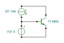
If the gain of the transistor was infinite (at all frequencies), there would be no ripple at the output.
If the dynamic impedance of the current source was infinite or the dynamic impedance of the voltage source was zero, there would be no ripple at the base.
If the gain of the transistor was infinite (at all frequencies), there would be no ripple at the output.
If the dynamic impedance of the current source was infinite or the dynamic impedance of the voltage source was zero, there would be no ripple at the base.
Attachments
What does that mean with regards to the topic?
Does a bridged amplifier only need half the energy storage, when compared to a non-bridged amplifier as megajocke claims? Or does it need the same energy storage to achieve the same performance, which I think it does?
Does a bridged amplifier only need half the energy storage, when compared to a non-bridged amplifier as megajocke claims? Or does it need the same energy storage to achieve the same performance, which I think it does?
you meant to use a single supply, not actually skipping the ground? Why do you keep repeating over and over again that you can use a single supply with a bridged amplifier, when it doesn’t change anything about the energy storage and when you can do the same thing with a non-bridged amplifier?
Because you post capacitance values for split-supply bridge amplifiers, trying to make it seem like bridge amplifiers need 4 times the size capacitors for the same performance while this is, in fact, the same energy storage. You wrote "2.8 times the capacitance" like it needs bigger capacitors even in that case too, while this is in fact 0.7 times the energy storage.
The output signal determines how deep the valleys are. Their position only changes slightly and will always be shortly before the peak of the mains voltage, therefore around 2 x fmains, not depending on the audio frequency.
But, just because the output signal and mains are not synchronized you can be sure that the ripple valley and signal peak will coincide from time to time, clipping the output, if output peak voltage is higher than ripple valley minus rail loss in amplifier. For 10ms bursts or so you can go above that safely, but that's one of those ugly marketing output power-inflating tricks.
It won't do sine even for semi-short intervals if peaks of the output go above that level, valley minus rail loss.
You think RC is higher for a bridged amplifier?
The bridged amplifier draws 1,4 times the current from half the voltage. That corresponds to a 2,8 times lower R. And you are advocating half the energy storage. That means twice the capacitance at half the voltage. When did 2/2,8 become bigger than one?
For the same energy storage:
Bridge: 30mF rail-to-rail (50V rail-to-rail)
Non-bridge: 15mF per rail (+-50V for example)
Bridge amplifier in clipping: 30mF directly connected to load
Non-bridge in clipping: 15mF directly connected to load
Half the corner frequency for the same energy storage. I haven't looked much into why the corner frequency while in clipping would matter, but it is something to do with NFB stability/motorboating/clipping recovery from what I've understood.
…, but only half the time. The bridged amplifier needs 0,7 times the energy storage for the same corner frequency.
Doesn't matter, as it is the turnover frequency during the interval when supply and load are directly connected (clipping) that supposedly matters.
This makes no sense at all to me. The last time you told me rms values don't matter, I posted a link that prove the opposite. Please, save me the work to look for another link.
Which link? Do you mean the Ripple page on Wikipedia? It gives formulas for calculating the RMS value of ripple in a capacitor filtered power supply. That's fine and dandy if you want to know the RMS value of the ripple - some loads may care about RMS ripple voltage so formulas for calculating it are useful. However, just because formulas for calculating it do exist doesn't mean that it's what matters. That depends on the load.
The page doesn't say anything about audio amplifiers caring about RMS value of the ripple. RMS values are used for calculating power in resistive loads. There is no resistance low frequency AC-coupled to the power supply in an audio amplifier so it has no importance.
Clipping is instantaneous, so it is unrelated to RMS of the AC component of the PSU voltage. PSRR is frequency dependent, making it unrelated to non-correspondingly-high-passed-RMS too.
If waveforms were the same there would be a fixed relation between RMS and all other properties of the ripple, making it possible to use RMS as a metric of performance, but in this case the waveforms are different so it isn't possible to do that.
It is the other way round? Rules of thumb cover the general case, but not the specific.
No, I mean special and general in their mathematical and logical sense, not the illogical colloquial sense. A general theory/rule needs to counter for all possible cases, while a specific one can be made to cover only those seen most often or some specific application.
Examples of special cases:
* The ripple formulas on Wikipedia are for DC current drawn from power supply
* I_rms = sqrt(I1_rms^2 + I2_rms^2) only works for orthogonal currents (you misused it on non-orthogonal currents a couple of posts ago)
* Design a PSU for 5% RMS ripple - that kind of rule-of-thumb makes assumptions about the load
Examples of general cases:
* Maxwell's equations and everything that derive from them 🙂
* I_rms_of_sum = sqrt(mean_over_time( (i_1(t) + i_2(t))^2 )) works for all currents
* Determine power supply requirements based on the specific load
Maybe you can explain, what changes in the relationship, if you use higher voltages. You will still have more losses in the bridged amplifier and by the same factor.
Diode drops are absolute voltages, making them relatively smaller when PSU voltage is increased. A three deep darlington or rectifier has a non-negotiable number of these.
There is a ground in mine, so there the ripple values will be doubled.
You posted "ripple values will be doubled" in response to MY picture which DOESN'T have a ground. In that context it couldn't matter less what your schematic looks like.
How would you describe the clipping in that image in terms of sonic quality? And how would it compare to an amplifier that clips only half as often?
Gainclown clipping sure looks broken. 😀 You didn't increase power supply voltage to compensate for the higer rail loss, did you?
By the way, the red ripple is the added voltage of the bridged amplifier with 88 mF per rail, while the green ripple is one rail of a non-bridged amplifier with 22 mF per rail. The rms ripple is still about 10 % worse for the bridged amplifier.
Does the bridged amplifier have an advantage at lower audio frequencies or not? If it explicitly has one, it implicitly has none at higher audio frequencies. Hence, if the advantage leads to less energy storage at lower frequencies, the lack of an advantage at higher frequencies leads to the same energy storage at higher frequencies. The above picture proves it.
It has an advantage at lower frequencies, PSU-wise. At higher frequencies it doesn't. If I design for say 10% pk-pk ripple at full power, 20Hz-20kHz output, low frequency gives the worst case ripple and thus LF performance determines smoothing capacitance. Half the energy storage in a full-bridge in that case. Same thing happens if I design for a certain RC turnover during clipping.
If you design for a certain percentage of ripple at 1kHz and don't care about LF performance being worse for a non-bridge you get the same energy storage for both configurations.
I'd choose non-bridged with one channel inverted though if in a stereo amplifier with reasonable PSU voltages. Practically no extra parts needed and gives better performance at LF. Can you see any (non-snake oil) disadvantages compared to running both channels in phase?
It allows for easy bridging too, without any reconfiguration. Just connect load between non-inverted channel positive output and inverted channel negative output and give both channels the same input signal.
Last edited:
pacificblue,
I`m trying to provide relevant information, but it is extremely difficult to know what you consider relevant. Our points of view are different.
The task of power supply capacitor is complex and demanding, serving as energy storage and filter component, signal wise being in series with the load.
A bridged amp with the same supply voltage can produce twice as large a voltage swing across the load, giving four times more output power, since power is proportional to the resistance and to the square of the voltage. Therefore, you could go for lower rail voltages, meaning larger capacitance for the same physical size and expense. This is audio. Some people count power supply capacitance in Farads. Be generous, you can`t reach detrimental levels and you won`t regret it.
No.Does a bridged amplifier only need half the energy storage, when compared to a non-bridged amplifier
You wrote "2.8 times the capacitance" like it needs bigger capacitors even in that case too, while this is in fact 0.7 times the energy storage.
How much capacitance gives 0,7 times the energy storage at half the voltage?
But, just because the output signal and mains are not synchronized you can be sure that the ripple valley and signal peak will coincide from time to time,
And which is better then? Is it better to clip half as often or is it the same?
Bridge amplifier in clipping: 30mF directly connected to load
Non-bridge in clipping: 15mF directly connected to load
Again, the non-bridged is only connected to the load half the time, which is the same as using half the load aka double the impedance.
Doesn't matter, as it is the turnover frequency during the interval when supply and load are directly connected (clipping) that supposedly matters.
The frequency is doubled in the bridged amplifier. Remember your lecturing about current draw from the rails looking like half-wave (1 x f) and full-wave (2 x f) rectified sine waves?
Which link?
Your statement:
If it isn't obvious why you can't use average current in ripple calculations, when the frequency of the load current is low, I can't help you.
My link:
In this document from the Panasonic website it says on page 1 "Ripple current is the rms value of alternating current flowing through a capacitor".
And please reread the prevening posts, before you start nitpicking about the difference between average and rms.
Diode drops are absolute voltages, making them relatively smaller when PSU voltage is increased. A three deep darlington or rectifier has a non-negotiable number of these.
So, what changes in the relationship? If voltage is increased, the diode drops become relatively smaller in both types of amplifiers. In the end you have double the losses in the bridged amplifier, whether the voltage is low or high.
You posted "ripple values will be doubled" in response to MY picture which DOESN'T have a ground. In that context it couldn't matter less what your schematic looks like.
Gainclown clipping sure looks broken. 😀 You didn't increase power supply voltage to compensate for the higer rail loss, did you?
If you can't muster the time or patience to read and understand my posts, we are both wasting time and should really finish this thread.
It has an advantage at lower frequencies, PSU-wise. At higher frequencies it doesn't. If I design for say 10% pk-pk ripple at full power, 20Hz-20kHz output, low frequency gives the worst case ripple and thus LF performance determines smoothing capacitance. Half the energy storage in a full-bridge in that case. Same thing happens if I design for a certain RC turnover during clipping.
You obviously still have not noticed that we are talking about two ripples, and you connect energy storage to the wrong one.
Ripple 1 is the power supply ripple that is described by the textbook formulas. It depends on the power that is drawn and it makes no difference, if the load is esistive or reactive. If you look at that from the energy storage point of view, you have the same power draw in both amplifiers and the same frequency (2 x fmains) to buffer, which can only lead to the same energy storage requirement for both amplifiers.
Ripple 2 is the ripple that corresponds to the audio frequency at which power is drawn. It represents the voltage drop across the power supply's inner resistance and is not connected to the energy storage. If you want to reduce that ripple, you need to use a transformer with low inner resistance aka low regulation aka a big one. And you need to use capacitors with low ESR aka big ones. The nice side effect of dealing with ripple 1 is, as you increase capacitance, ESR decreases and you usually need not worry additionally about ripple 2.
Then there is ripple 3, which Lumba Ogir introduced to the thread. That is the ripple (proportion of ripple 1 + ripple 2) that makes it through to the speaker terminals. PSRR describes the amplifier's capability to deal with that. In the case we are looking at, each half of the bridge has the same PSRR as the non-bridged amplidier. If you add that up, PSRR is half as good in a bridged amplifier, and it needs half the ripple on each rail to achieve the same amount of ripple at the speaker terminals. Half the ripple on each rail at lower voltage and higher current draw means what with regards to capacitance/energy storage?
My impression is that your posts are becoming more and more aggressive, which seems to indicate that you take things far too personal to be good. I am really contemplating not to post further in this thread to avoid an unpleasant outcome.
pacificblue,
I`m trying to provide relevant information, but it is extremely difficult to know what you consider relevant.
Thanks for the effort and yes, this thread must be quite confusing, if you did not participate in it from the start.
To give you a short summary, it started with megajocke posting an amplifier schematic of a bridged amplifier with single supply in a thread, from which this here was split off. Then he stated that bridged amplifiers only need half the energy storage of non-bridged amplifiers. This got mixed with occasional references to single supply vs split supply. It was also spiced up with my hint that you need capacitors with higher ripple current rating for a bridged amplifier.
I appreciate that finally somebody else confirms at least one of my points of view.
I thought I was also on your side.
Two amplifiers driving a half impedance load will draw 4times a much current as one amplifier driving the nominal impedance load.
From that we can infer that two bridged amplifiers need 4times as much capacitance and will provide 3 to 4times as much power as the single amplifier into that nominal load.
Yes, and the ripple factor formula leads to the same capacitance for any amplifier that sees the same load impedance, regardless of rail voltage and output power. That would have worked, if megajocke had accepted the validity and relevance of that formula.
AndrewT: This thread is about amplifiers of the same power rating. To a first approximation you are right, as you are comparing amplifiers with a 4 times difference in output power at the same voltage. However, non-bridged amplifiers have increasing ripple towards low frequencies which makes the energy storage needed for a certain ripple higher if ripple needs to be kept below a specified amount over the whole frequency range of the amplifier.
Comparing bridge and non-bridge of the same output power:
With high frequency output, PSU-wise, there is no difference between the two configurations. Same energy storage for the same ripple-RMS to DC ratio (ripple factor gamma) or pk-to-pk to DC ratio for amplifiers of the same power rating.
With low frequency output, there will be more ripple than at high frequencies in a non-bridged amplifier. Peak-to-peak ripple to DC voltage ratio is ~2 times higher than at high frequencies as simulation (and reality) shows. RMS ripple to DC voltage ratio (gamma) is also somewhat higher than at high frequencies.
Now, if ripple is this much higher at low frequencies, doesn't that mean that energy storage needs to be doubled to compensate? (or increased by a factor of 1.5 if the same RMS is enough for you)
A non-bridge of a certain power then needs double the energy storage for the same peak-to-peak to DC ripple ratio compared to a full-bridge, which practically doesn't show this increase towards low frequencies. This is the same thing as a full bridge only needing half the energy storage of a comparable non-bridge. But of course, this is only true if the non-bridge had enough capacitance to begin with to make ripple at low frequencies within specifications.
What I'm saying is really that a non-bridge needs more energy storage than what might be thought at first, not that a full-bridge needs less.
Well, you are so confident that you are right and believe that your knowledge is superior to everyone else that you can't bother to read and/or understand what I write. You can't just skip parts of sentences like "during the interval when supply and load are directly connected" expecting the sentence to mean the same afterwards. Your reply was based on conveniently skipping that part.
You also post a lot of things that are correct, but out of context, irrelevant and misleading. For example, a link that states the obvious fact that ripple current in a capacitor is the RMS current through it. You posted this as a reply when I wrote that ripple voltage from the power supply increases towards low frequencies of output from the amplifier while output power is kept constant.
In your last post you mentioned that there are different ripples on the power supply. The power supply isn't linear however (diode conduction), so you can't split it up that way. Superposition and thevenin equivalents only work for linear networks. Modelling the PSU as a voltage source with output resistance is a good approximation for the average output voltage however.
So you are right, if you can't bother to read my posts without skipping every other word/sentence or so there is little point in this.
Comparing bridge and non-bridge of the same output power:
With high frequency output, PSU-wise, there is no difference between the two configurations. Same energy storage for the same ripple-RMS to DC ratio (ripple factor gamma) or pk-to-pk to DC ratio for amplifiers of the same power rating.
With low frequency output, there will be more ripple than at high frequencies in a non-bridged amplifier. Peak-to-peak ripple to DC voltage ratio is ~2 times higher than at high frequencies as simulation (and reality) shows. RMS ripple to DC voltage ratio (gamma) is also somewhat higher than at high frequencies.
Now, if ripple is this much higher at low frequencies, doesn't that mean that energy storage needs to be doubled to compensate? (or increased by a factor of 1.5 if the same RMS is enough for you)
A non-bridge of a certain power then needs double the energy storage for the same peak-to-peak to DC ripple ratio compared to a full-bridge, which practically doesn't show this increase towards low frequencies. This is the same thing as a full bridge only needing half the energy storage of a comparable non-bridge. But of course, this is only true if the non-bridge had enough capacitance to begin with to make ripple at low frequencies within specifications.
What I'm saying is really that a non-bridge needs more energy storage than what might be thought at first, not that a full-bridge needs less.
If you can't muster the time or patience to read and understand my posts, we are both wasting time and should really finish this thread.
Well, you are so confident that you are right and believe that your knowledge is superior to everyone else that you can't bother to read and/or understand what I write. You can't just skip parts of sentences like "during the interval when supply and load are directly connected" expecting the sentence to mean the same afterwards. Your reply was based on conveniently skipping that part.
You also post a lot of things that are correct, but out of context, irrelevant and misleading. For example, a link that states the obvious fact that ripple current in a capacitor is the RMS current through it. You posted this as a reply when I wrote that ripple voltage from the power supply increases towards low frequencies of output from the amplifier while output power is kept constant.
In your last post you mentioned that there are different ripples on the power supply. The power supply isn't linear however (diode conduction), so you can't split it up that way. Superposition and thevenin equivalents only work for linear networks. Modelling the PSU as a voltage source with output resistance is a good approximation for the average output voltage however.
So you are right, if you can't bother to read my posts without skipping every other word/sentence or so there is little point in this.
Last edited:
pacificblue,
No, not at all. Load impedance is not part of the formula. Current is.
You are right, when you think about the ripple voltage formula. The ripple factor formula contains R, because it puts ripple voltage in relation to the rail voltage.
Well, you are so confident that you are right
Yes, I am. Think about, how many people do not share your opinion so far. AndrewT, Jan Dupont, Lumba Ogir and me. All four of us are engineers, each with many years of experience. How probable is it that you are right and we are all wrong?
Your profile says that you are a student. Why don’t you ask one of your professors for an opinion?
and believe that your knowledge is superior to everyone else
No, I don't. If you can prove something that I didn’t know before or that I was wrong about during the last twenty-something years, I will actually be pretty happy. That will help me avoid mistakes in the future. Until now however you have not provided any reliable source that supports your opinion and I am pretty sure you will not be able to provide one in the future.
There is one more thing you should take into consideration. Being of a different opinion does not mean that I have anything against you. So, please take that acid out of your posts.
For example, a link that states the obvious fact that ripple current in a capacitor is the RMS current through it.
You posted this as a reply when I wrote that ripple voltage from the power supply increases towards low frequencies of output from the amplifier while output power is kept constant.
No, I didn't.
In your last post you mentioned that there are different ripples on the power supply. The power supply isn't linear however (diode conduction), so you can't split it up that way.
Most of the time the power supply is linear, because current is drawn only from the capacitors. It is only non-linear during the short portion of time, when the transformer voltage is higher than the capacitor voltage.
Whether non-linear or not does not change the mechanism at work. Being non-linear means it is a bit more difficult to calculate, if you want to know the absolute exact value. But still the ripple that corresponds to the audio frequency is due to the voltage drop across the power supply’s inner resistance.
Now, if ripple is this much higher at low frequencies, doesn't that mean that energy storage needs to be doubled to compensate?
No, because more energy storage will only reduce the 100 Hz ripple from the power supply. You need lower ESR to reduce the audio frequency ripple. If you try with the same capacitance and lower ESR, you will get better results than with higher capacitance and the same ESR, if you only look at the ripple that corresponds to the audio frequency. Of course in real life higher capacitance leads to lower ESR, so it is difficult to separate both things clearly, except in a simulation.
pacificblue,
the ripple voltage formula is to be found in post #45. No R and no rail voltage as far as the eye can see.
the ripple voltage formula is to be found in post #45. No R and no rail voltage as far as the eye can see.
No, because more energy storage will only reduce the 100 Hz ripple from the power supply. You need lower ESR to reduce the audio frequency ripple. If you try with the same capacitance and lower ESR, you will get better results than with higher capacitance and the same ESR, if you only look at the ripple that corresponds to the audio frequency. Of course in real life higher capacitance leads to lower ESR, so it is difficult to separate both things clearly, except in a simulation.
Ah, so you're looking at the ESR voltage drop. Then you're right, those add up quite well. I was referring to power supplies where ESR drop is insignificant compared to 100Hz ripple voltage. For very low impedance loads at high powers ESR does become an issue.
I'm sorry if the tone in my posts seemed harsh. 🙂 Internet discussions have a tendency to become confused.
You want me to point out errors? 😉
See waveforms in Post #42. The ripple voltage from a power supply does depend on the frequency of the current that is drawn from it. It is not independent of frequency as you state. The difference between low and high frequency is actually even worse for half sine wave current, like that drawn by a non-bridged amplifier outputing a sine wave.There is no improvement for lower frequencies in bridged amplifiers. The ripple voltage changes with the amount of current, not with the frequency at which current is drawn.
Here you wrongly assumed that the currents are orthogonal. This formula can only be used if I[(f(t) + g(t))^2*dt] = I[(f(t)^2 + g(t)^2)*dt]. This is only the case if I[(f(t)*g(t))*dt] = 0, where I[ ] is supposed to mean the integral over the time considered. f and g are the two currents.Ripple current Irms = sqrt(Ichargerms² + Idischargerms²). The charge current through the rectifiers is doubled, see above. The discharge current through the amplifier is sqrt(2) times higher, see your post #16. Therefore the ripple current is sqrt(6) = 2,45 times higher for the bridged amplifier, which means the capacitor(s) for a bridged amplifier need a higher ripple current rating.
In the PSU case the currents never cross 0A. One is always non-positive while the other is always non-negative. This means that if they ever flow at the same time, which they do, the f*g integral will be less than zero. The integral being non-zero breaks the formula.
Not for ripple voltage if frequency of drawn current is low as shown in Post #42. A higher crest factor also means higher RMS current for a certain average current, so heating in power supply parts can be higher although average output power from the PSU is the same.Crest factor or peak-to-average ratio is a non-issue in unregulated power supplies.
- Status
- Not open for further replies.
- Home
- Amplifiers
- Solid State
- PSU capacitor design