Salas said:Is that horizontal part still double lined if you feed your calibration directly to the scope? Or there is a gremlin....
I'll have to check again tonight. Only the camera got that, with the naked eye I see only one line.
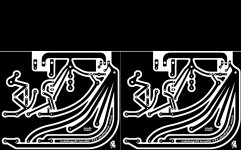
Salas Simplistic HV Regulator PCB
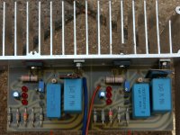
Last week I did a pcb design for this circuit. Since a couple of days I've got two of them working on a small (2A3) amplifier. They do a good job regulating and sonics are very good. Dynamic, precise but musical I would comment.
There are a few peculiarities about the circuit board.
- when the output is shorted, you'll have to replace the semi's 😱
Some simple alterations can make it fool proof. More on this subject will follow;
- C1 (100uF/10V) is at a high potential. Do not touch while live if the can is not isolated;
- connecting wires shouldn't have excessive length for best results;
- for R2 and R7 it's better not to use metal film;
- R2 is mounted at the back;
- R3 and R9 (in the higher voltage version) are 82K/5W. If you can't locate these there's space to double a 150K/2W and a 180K/2W. These resistors get hot on full 400V!;
- the initial version suffered from heat building up in Q2 so I had to use a heatsink on the small TO-92 transistor. It occurred while the reg was dissipating 45mA at 295V into Q3 (over 13W). This renewed board is more spacious for better air flow around the components;
- if necessary a 47 ohm base stopper on Q2 can be inserted by breaking the copper trace between Q2 and C2 (see purple trace).
Hope you enjoy it as much as I do
Attachments
Last edited:
 Good tight job. Do you pre filter it? Any optional clamping zeners pads against shorting mishaps? I think you use the Swenson Mosfet HV reg too? Different sonics?
UNfortunately my file is too big for the forum (740KB). The resolution is 1200DPI for a 10x16cm board (eurocard size). It's located here.
Can´t get the link to work. Something that can be fixed?
Can´t get the link to work. Something that can be fixed?
The link works in my browser but here it is again, attached.
Attachments
Well, experimenting is part of the fun, isn't it? 😛
First tests were on a bench power supply at 345V input, 50mV ripple.
Second I made a 340V PSU with 2.3V ripple (ok, that's a lot).
Last I improved this PSU to 350V with 0.7V ripple (not too good either).
Both PSU's used small caps and a 10H choke, ripple was sinusoidal.
The voltage margin (input to output) was 40 to 50 volts, current margins were circa 50% to 40% (75mA to the load, 40mA to the sink etc).
With all tests I measured no AC at all after the reg. 😎
Regarding the second part of your reply, I'm constructing a straight forward 2A3 amplifier to test the several regulators I've built so far.
There's metalwork involved so it takes some free float to complete.
The link is OK, the problem might be a temporary unobtainable host because of 'data stress'. If not send me a PM.Can´t get the link to work. Something that can be fixed?
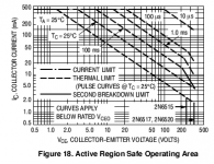
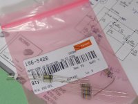
298V & 460mW. He utilized VCBO and SOA almost all the way. Wise to have done the TO-92 sink. Imagine how it derates in a hot environment near the sinks. MPSA94 is an alternative and it can go near 400V. Those TO-92s keep up decent hfe at 1-2mA we use here.
Attachments
6V6 pre-amp
Salas,
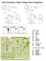
Happy to read through the whole thread and would like to replace the Maida supply with the Reg. above for the 6V6 pre. - your design.
1). I'd use one PTX for two boards and will use MPSA94 for Q2, I have some in hand.
2). Do I have to change anything to optimize the design?
Thanks
Albert
And the higher example.
Salas,
Happy to read through the whole thread and would like to replace the Maida supply with the Reg. above for the 6V6 pre. - your design.
1). I'd use one PTX for two boards and will use MPSA94 for Q2, I have some in hand.
2). Do I have to change anything to optimize the design?
Thanks
Albert
Just set the Reg at 75mA CCS 330Vout R1=27R. If with individual reg per channel, no less than 45mA CCS R1=47R. Lower, it loses transiently. MPSA94 is perfect. Maybe you will need about 20% smaller R5 to get to your needed Vout with the MPSA. Vout slides until thermal stability of the output driver BJT. You will see in practice. Sink it as Disco did, you go high voltage, it needs to be stable. Use the new Russian ''Tungsol'' 6V6GT, TKD 100k pot, and 2.2uF to 3.3uF output capacitor, Mundorf normal supreme. Make an elastically decoupled subchassis for the tubes. Like a TT armboard.
Or you have already made it and you need only to change the reg? If yes tell me more about your experience with it.
Or you have already made it and you need only to change the reg? If yes tell me more about your experience with it.
Just set the Reg at 75mA CCS 330Vout R1=27R. If with individual reg per channel, no less than 45mA CCS R1=47R. Lower, it loses transiently. MPSA94 is perfect. Maybe you will need about 20% smaller R5 to get to your needed Vout with the MPSA. Vout slides until thermal stability of the output driver BJT. You will see in practice. Sink it as Disco did, you go high voltage, it needs to be stable. Use the new Russian ''Tungsol'' 6V6GT, TKD 100k pot, and 2.2uF to 3.3uF output capacitor, Mundorf normal supreme. Make an elastically decoupled subchassis for the tubes. Like a TT armboard.
Or you have already made it and you need only to change the reg? If yes tell me more about your experience with it.
Salas,
Yes, I made the pre-amp, and I just change the PSU this time. Will go with single PTX then to 2 seperated reg. Will certainly post the result after, but please be patient for I'm packing up to move to a new home. It might take some time to make it finish.
The 6V6 with Maida won all the pre-amp I made before. It sounds rich and punchy and with lots of delicate highs. I like the vocals the most with new Tungsol reissue, but didn't have chance to compare with others tubes/brands.
Thanks again
Albert
Won all the pre amps you had? Good news. OK the double 45mA shunt will make it sing even more for sure. Don't you have a picture of the preamp to see it?
Won all the pre amps you had? Good news. OK the double 45mA shunt will make it sing even more for sure. Don't you have a picture of the preamp to see it?
Sorry, it's all packed.
Will show you after I have my new audio room set up.
OK, good luck with moving. Use Disco's PCB if you make PCBs, or at least follow its layout as a guide for P2P. Its practical and worked OK.
- Home
- Amplifiers
- Power Supplies
- Simplistic mosFET HV Shunt Regs