Hi Eva, bjorno, all
A couple thoughts;
Eva said “In a tapped horn the phase varies wildly across the passband” and “Phase matching a mid/bass system and a tapped horn is already difficult enough.”
Perhaps in what you’re looking at but normally a measurement trumps a computer model. Simply, some features that are predicted in Akabak don’t exist in the physical item.
If your going to have faith in a prediction it has to be founded on some track record comparing with measured results. I can tell you Akabak which I use has some issues, it would be no fun at all to tell you what to do anymore than pointing out a trail.
If your first statement were true, where exactly do you see this in the measured response of say a th-215? Keep in mind, in the Tapped horns that aren’t as flat with just one unit, if you choose to eq them flat, you generally correct the phase response.
Also some Tapped horns have as little as approaching half the measured GD associated with it’s low corner compared to a vented box with the same corner F (due to it being a quarter wave 90 degree resonator and not an 180 degree inverter). This much of a difference might be audible and why they sound different.
http://www.danleysoundlabs.com/pdf/TH 215 Spec Sheet.PDF
The spud is a new product, we have not done the normal formal outdoor half space measurements yet pending time and weather.
So far as using them in a full range system, a Tapped horn is part of at least five of our full range products including the SH-50.
Keep in mind, our stand alone subwoofer products are normally used below 70-80Hz as the spud is for home theater use.
Merry Christmas, Happy Holidays and good sound to all!
Tom Danley

The problem with tapped horns are the two propagation paths from the speaker to the mouth having very different lengths. This causes several jumps in group delay. Hornresp does *not* model this in any way. Horn phase plots produced by Hornresp are completely useless.
My experience is based in real double 15" super-scooper type cabinets. These are much better behaved than tapped horns in the midbass region, yet they are quite difficult to integrate with other midrange and subwoofer systems due to the phase jumps, requiring extensive phase shifting and EQ for proper on-axis summing.
My experience is based in real double 15" super-scooper type cabinets. These are much better behaved than tapped horns in the midbass region, yet they are quite difficult to integrate with other midrange and subwoofer systems due to the phase jumps, requiring extensive phase shifting and EQ for proper on-axis summing.
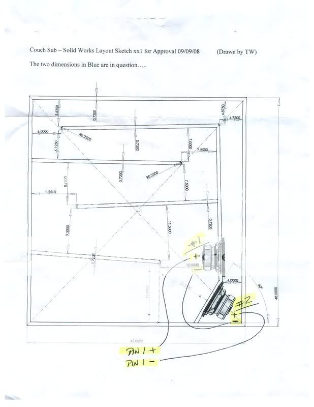
I am wondering how long is a *good* long and how long is *too long*?
If I'm building a sub that I want reasonably flat down to 20Hz, with the Dayton Titan MkIII 15" driver:
Frequency range: 19-500 Hz * Magnet weight: 136 oz. * Fs: 24 Hz * SPL: 91.7 dB 2.83V/1m, 88.7 dB 1W/1m * Vas: 5.46 cu. ft. * Qms: 6.75 * Qes: .52 * Qts: .49 * Xmax: 20.5mm
,,,,,then how long is too long and how short is too short? In my current drawing, I'm looking at a distance of 9 feet on each side of the driver that twists and turns through a cabinet.
If both passages are of the same length, then wouldn't this balance out the equilibrium problem?
Hello,
look what happens by using two different horns,
you get more bass and a partiell delete over 100 Hz,
where normally such horns rise the SPL ~10 dB,
so it is useful up to 200 Hz, BUT driver position in the horn mouth
is for HiFi only useful up to 100 Hz.
I made two alternative studies for 16 cm driver
http://www.hm-moreart.de/108.htm
scoll down
here the imp of the SUBfanfare:
both
single a
single b
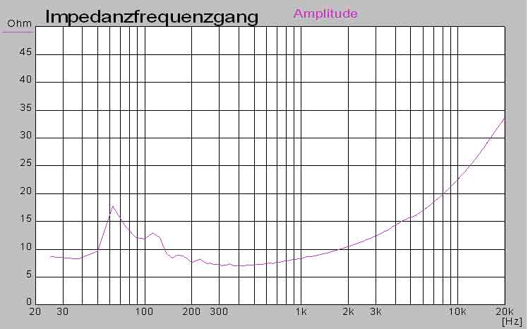
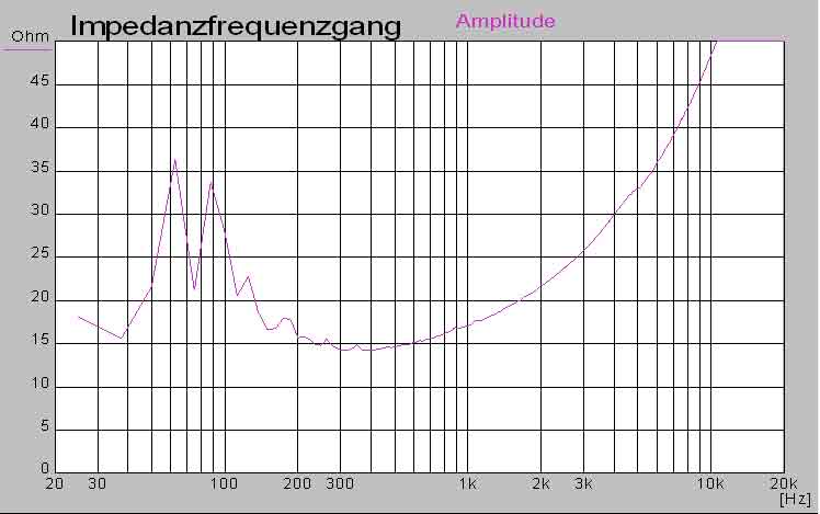


Place two identical horns together and you will get true impedance and frequency response flattening too (each one will be flatter), but without cancellation.
djk said:An interesting driver for a low profile box:
http://www.parts-express.com/pe/pshowdetl.cfm?&DID=7&Partnumber=264-838&ctab=2#Tabs
In an 18hz TH a series pair will be 96dB (at 20hz) in 2Pi and take 40V without exceeding x-max. Average about 118dB/40V, ±2dB from 18hz~60hz.
Of course room gain or 1Pi loading would add to this.
djk - did you model this driver? It looks very interesting, as I'm getting ready to build something similar to this, but the added displacement of those drivers vs a standard 8" would only make things better for HT use, giving more output.
I've got up to 8' x 8' x 14" to use for the riser, so I'm thinking I'd be able to use several of them 😀 in an enclosure that would play a little below 20hz..
Still learning Hornresp, or I'd post my own graphs...
So after some time I've been working again on my tapped horn.
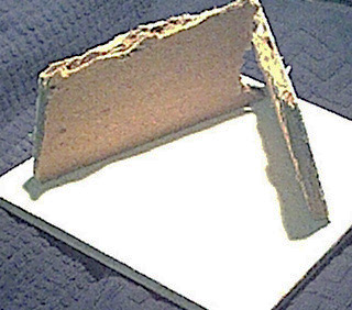
I decided to follow William's advice and use the W8-740. Its quite cheap and has a good x-max and modelled quite good in the application. I also learned this is probably also the driver Tom Danley is using. The only difficult thing to model correct seems to be the stuffing of the horn. I tried some ways in Akabak but its almost impossible to know what value is correct without being able to compare it with reality:so it was time to make some saw dust! So after one weekend of hard work I came to this result:

I will keep the side removable for now to be able to adapt the stuffing inside. I started out with almost everything lined with 3 cm polyesterfilling as I hope this would be a good starting point.
I have not been able to do any measurements up to now. Maybe next weekend. Just for a try, I connected it to one channel of my 70W amp and it was quite able to shake everything in the house.
I decided to follow William's advice and use the W8-740. Its quite cheap and has a good x-max and modelled quite good in the application. I also learned this is probably also the driver Tom Danley is using. The only difficult thing to model correct seems to be the stuffing of the horn. I tried some ways in Akabak but its almost impossible to know what value is correct without being able to compare it with reality:so it was time to make some saw dust! So after one weekend of hard work I came to this result:
I will keep the side removable for now to be able to adapt the stuffing inside. I started out with almost everything lined with 3 cm polyesterfilling as I hope this would be a good starting point.
I have not been able to do any measurements up to now. Maybe next weekend. Just for a try, I connected it to one channel of my 70W amp and it was quite able to shake everything in the house.
Hello,
nice,
to see measurements and Imp,
if you taken triple soft fibre inside you won´t need
damping material, most needed the first 1-1,5 m to
reduce "Schallschnellen" above 100 Hz,
it looks more like a TML!
nice,
to see measurements and Imp,
if you taken triple soft fibre inside you won´t need
damping material, most needed the first 1-1,5 m to
reduce "Schallschnellen" above 100 Hz,
it looks more like a TML!

Very very nice 🙂
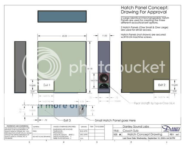
Did you use the leaked Danley plans for the TH-SPUD? Any deviations?
I see you also used the W8 driver. I'm looking forward to hearing your results.
Did you use the leaked Danley plans for the TH-SPUD? Any deviations?
I see you also used the W8 driver. I'm looking forward to hearing your results.
I used more or less the same dimensions as the original
I managed an impedance measurement today. Tuning seems quite low, so maybe a bit too much filling. To do a freq respons measurement will take more time as I am not able to lift the heavy thing outside on my own.

I managed an impedance measurement today. Tuning seems quite low, so maybe a bit too much filling. To do a freq respons measurement will take more time as I am not able to lift the heavy thing outside on my own.
Thanks for the impedance graphs. As much as I am sure everyone would love to see outside measurement graphs. An inside one would be okay to pacify us for a little while!
Nice work 🙂
Nice work 🙂
Hi geitmans,
That's a great workup you put together here. Very well done!
Did you end up using plywood, and would you please post a closeup of the driver/access port area? Any more FEA analysis plots you could share? Looking forward to your response measurements.
Regards,
That's a great workup you put together here. Very well done!
Did you end up using plywood, and would you please post a closeup of the driver/access port area? Any more FEA analysis plots you could share? Looking forward to your response measurements.
Regards,
I used birch plywood because it seemed its quite a bit more stiff than OSB. The FEA plot remains the same only the first resonance mode went up to about 200Hz. I haven't done yet tests to see how close this is to reality.
Here is a detail of the access ports. I used threaded inserts and M4 screws to connect everything.
Here is a detail of the access ports. I used threaded inserts and M4 screws to connect everything.
An externally hosted image should be here but it was not working when we last tested it.
Here is a first measurement in my living room with the mic close to the mouth (mouth upwards in the middel of the room)
Tuning is indeed a bit low. I suspect the big dip at 60 Hz is a room effect. The stuffing does quite a good job filtering away the highfrequency content.
An externally hosted image should be here but it was not working when we last tested it.
Tuning is indeed a bit low. I suspect the big dip at 60 Hz is a room effect. The stuffing does quite a good job filtering away the highfrequency content.
Mouth up in the middle of the room is probably the worst spot in the room to measure from. Maybe try moving it around a bit and see if you can get rid of the big dip. Moving it outside and measuring should do the trick. That dip shouldn't be more than about 6db deep in my estimation.
room effect
Hi geitmans,
The stuffing seems to be doing it's job. The big dip is most probably a room effect, and it doesn't help that it coincides with a big dip in the hornresp SPL response curve. Turning the port to the floor, and changing the position will change the position of the room effect.
Regards,
Hi geitmans,
The stuffing seems to be doing it's job. The big dip is most probably a room effect, and it doesn't help that it coincides with a big dip in the hornresp SPL response curve. Turning the port to the floor, and changing the position will change the position of the room effect.
Regards,
Thumbs up
You realise you almost squeezed out three octaves between 15hz and 120 hz!
That's pretty good geitmans.
Mark
You realise you almost squeezed out three octaves between 15hz and 120 hz!
That's pretty good geitmans.
Mark
WOW really impressed with both your 3D drawing and you're preliminary response graph.
How does it sound? Hows the sensitivity and SPL?
Regarding placement, have you tried corner loading them similar to this:

Very excited to see these positive results 🙂
Great contribution.
How does it sound? Hows the sensitivity and SPL?
Regarding placement, have you tried corner loading them similar to this:
Very excited to see these positive results 🙂
Great contribution.
- Status
- Not open for further replies.
- Home
- Loudspeakers
- Subwoofers
- Dual 8" tapped horn = TH-SPUD