Ok here goes. I've been looking around for quite some time now to find the ultimate amplifier schematic/setup/topology.
Somehow i came to this forum and learnt a lot allready. Especially in the X and alephX threads. The NP aproach with minimal components does sound very good to me.
Below some background info on the amp im building and some general and specific considerations about the X-amp setup.
- I'm a student so i would like to keep the costs down.
- I have two 1.6KVA 2x48V sec torroids wich will supply the juice for this amp (one torroid for each of the two mono-blocks)
- I managed to get 80! 4700uF 80V nippon 105C computer grade caps. I would like to use these for the amp as well.
- For rectifier i have some 35A metal rectifiers and some fast TO220 diodes, not sure if they are slow recovery, will check on that tuesday.
- It gets pretty hot in the listening room during summer so i would like to keep dissipation (well) below 500W idle, maybe some sort of 2 mode operation (winter/summer)This might be optimal solution. The rail voltage is fixed so not sure if this is realistic option.
- Because of the high sec voltage i dont think i can use a symetric supply. So it will be 48V with fantom ground. with symetric amp that shouldnt be that much of a prob
- My speakers are reasonably sensitive and the amps i use at the moment produce to much noise when iddle. So this is a very import criteria for the new amp, no hearable noise, even with ear next to speaker.
I have some considerations about the X amp.
- I do understand why there is no global feedback (to keep speakers from feeding noise into the amp and perhaps oscilation). But because the last stage uses non linear devices this non-linearity doesn't get compensated by feedback. (all active devices are non linear?)
What about using one dummy output stage that delivers into a resistor equal to xr times the load impedance. Were xr is equal to the number of paralell output devices. Then taking feedback from this resistor/stage. This would also solve the dreaded DC offset problems?. Or might this lead to oscilations because of the crosscoupled input stage?
- In the early days nelson recomended slow rectifiers even with 100nf MKP/MKT in paralel with the diodes. In the new XA series he uses fast diodes. Anybody know about this change?
- I see that the irfp240 is a popular device for pass amps. In a document on NP's site about mosfets he concludes that the irf9240 (although it should be) issen't a real good complement to the irfp240 (articles-mos-page9). The irfp9240 is used in many X schematics in the forum. In the commercial X amps are TO-3 hexfets, irfp240 is TO247. Maybe there is a better complementary pair to be used in X-amp?
- Is it possible to use the two 48 secondaries in paralel to have a higher current rating? Should this be done before or after rectifiers? with double or single rectifier? Using one sec winding for the left leg of the amp and the other for the right leg doesn't seem like good idea because there would be less noise cancelation in the supply lines.
- Im not sure about a good way to connect the caps for filtering. I could get them for a very good price. Because i want to use fantom ground they should be even more effective. But how much of them should i use and how to connect them physicaly? A big copper strip/star/plate? Perhaps R or L in between groups of them?
- I got a 2x 9V 4A sec torroid wich i was planning to use for the gain stage. (in serie with the 48V rails) After i read Petters X-amp thread im not sure if this will provide enough headroom.
- i was planning on building a regulated supply for the first stage. but this will cost even more voltage on the first stage.
- I read somewhere that conventional transformer would be more suited for gain stage then torroid. Although i think that torroid has better performance in EM noise radiation. Why would a conventional be better in supplying extra voltage for gain stage?
I know, a lot of information and questions. I would really apreciate it if someone could help me on some of these points.
Hope my english issen't a problem
Jacques
DiMenSioN said:.....................
- I do understand why there is no global feedback (to keep speakers from feeding noise into the amp and perhaps oscilation). But because the last stage uses non linear devices this non-linearity doesn't get compensated by feedback. (all active devices are non linear?)..............................................
Jacques
you lost me there...........
rethink.......
Those transformers are a bit high voltage for an X amp. You'll end up with about 67V rails, meaning you'll be able to swing around 130V as an X amp - a bit over 1KW RMS  Suddenly your 1.6KVA transformers don't seem so overkill. 😉
Assuming that you don't need that much power, a more conventional amp would make more sense. The A75 isn't terribly hard to modify to use with higher voltage rails. I've got a pair running with 65V on the front ends and 59V on the outputs. Just watch dissipation and voltage ratings. See Dinu's higher power A75 thread.
Suddenly your 1.6KVA transformers don't seem so overkill. 😉 Assuming that you don't need that much power, a more conventional amp would make more sense. The A75 isn't terribly hard to modify to use with higher voltage rails. I've got a pair running with 65V on the front ends and 59V on the outputs. Just watch dissipation and voltage ratings. See Dinu's higher power A75 thread.
you lost me there...........
What i mean is that all active devices (BJT FET MOST) have a nonlinear curve.
In case of a MOST (Id - Vgs curve).
This means that if you drive a most as a with a clean sinus that the output voltage (in a resistor) won't be a clean sinus. Even in source follower setup. You can compensate for this nonlinearity with feedback. I do agree that this nonlinearity is probably not very big, but still
Those transformers are a bit high voltage for an X amp. You'll end up with about 67V rails, meaning you'll be able to swing around 130V as an X amp - a bit over 1KW RMS Suddenly your 1.6KVA transformers don't seem so overkill.
Thats why i would like to use 48V with fantom ground, so its +24V 0(fantom) -24Volt. The question is can i paralel those 2 secondaries, and how? Is it even needed to paralel them?
The reason that linear amplifier is possible with MOSFET, BJT or whatever other active device there are, is that there is a region in the characteristic curve that is, or almost, linear, like a resistor. So nonlinearity is more a imperfection more than a inherit thing.
As for splitting 48V-0 into 24-0-24, I am not sure because I have never tried such.
Regard,
Peter
As for splitting 48V-0 into 24-0-24, I am not sure because I have never tried such.
Regard,
Peter
With those transformers, I think the A-75 would be the way to go as well. One good thing about the A-75 is that you can turn down the bias and it still works, so you have an out if your heatsinks turn out to be undersized.
You can't do that with an Aleph.
You can also use fewer output devices in the A-75 than are used in the Nelson's original article, if you wish to reduce costs and complexity somewhat.
JJ
You can't do that with an Aleph.
You can also use fewer output devices in the A-75 than are used in the Nelson's original article, if you wish to reduce costs and complexity somewhat.
JJ
jupiterjune said:With those transformers, I think the A-75 would be the way to go as well. One good thing about the A-75 is that you can turn down the bias and it still works, so you have an out if your heatsinks turn out to be undersized.
You can't do that with an Aleph.
You can also use fewer output devices in the A-75 than are used in the Nelson's original article, if you wish to reduce costs and complexity somewhat.
JJ
Havven't looked into the A75. I was not planning on building a aleph, aleph-X or XA. I ment the X*00.5 or the X*00
The alephs are indeed to hot. The X should be biasable to different values?
I don't know a thing about the X*00's. Based on Grey's last post about the aleph X followup, maybe it will have a little more in common with them.
I sort of mis-spoke when I said you can't reduce the bias in an Aleph, but doing so reduces the power output before clipping, wheras the A-75 still gives the same voltage out. Right now, I have the bias turned way down in mine and it is sitting inside a cabinet, driving my subwoofer, bridged.
JJ
I sort of mis-spoke when I said you can't reduce the bias in an Aleph, but doing so reduces the power output before clipping, wheras the A-75 still gives the same voltage out. Right now, I have the bias turned way down in mine and it is sitting inside a cabinet, driving my subwoofer, bridged.
JJ
I suppose a virtual ground situation would work with an X amp, with a balanced input.
X amps can probably run at reduced bias, but watch thermal compensation - Probably a good idea to put your Vgs multipliers on the main heat sinks if you go under 100 mA per device pair.
Regulated front end supplies are a good idea. With an extra 9 VAC you'll get 12V more raw DC , which will give you at least 7V above the output rails after regulation - plenty.
You could add the output devices to the feedback loop fairly easily even if Petter didn't. I'd eliminate the 400K resistors surrounding the bias pots (which should be replaced with Vgs multipliers like in the A75) and use a 200K from the output to the junction of the 400K's Petter shows.
If you go for 65 V rails on an A75, don't cut back too far on the number of output devices if you run a low impedance load.
- I see that the irfp240 is a popular device for pass amps. In a document on NP's site about mosfets he concludes that the irf9240 (although it should be) issen't a real good complement to the irfp240 (articles-mos-page9). The irfp9240 is used in many X schematics in the forum. In the commercial X amps are TO-3 hexfets, irfp240 is TO247. Maybe there is a better complementary pair to be used in X-amp?
I think Nelson mentioned somewhere that the Fairchild device makes a good compliment -- I am not sure where that post was, either on the f4 thread or on a thread inquiring where to buy mosfets.
JJ
If you want to use the Fairchild equivalents to the IRFP240/IRFP9240, the N-ch is the FQA19N20C and the P-ch is the FQA12P20. But the IRF still work as advertised.
Grey
Grey
DiMenSioN said:In a document on NP's site about mosfets he concludes that the irf9240 (although it should be) issen't a real good complement to the irfp240. Maybe there is a better complementary pair to be used in X-amp?
This is not correct. The IRF P channel parts have an odd
characteristic which shelves the transconductance in the mid
audio band. As such, it is somewhat flawed for use in
Common-Source applications, but it is acceptable in Common-
Drain use.
IR P channel parts made by other manufacturers, such as
Harris or Fairchild do not exhibit this.
In the case of X amps, it is not an issue.
😎
Re: Re: X amp considerations
just later I realize that you think and talk about real X , not Aleph X...
I was confused when you wrote about feedback,non-global........and that's exactly the case with real X
Zen Mod said:
you lost me there...........
rethink.......
just later I realize that you think and talk about real X , not Aleph X...
I was confused when you wrote about feedback,non-global........and that's exactly the case with real X
Thanks Mr Pass. Ill try to find the fairchild or harris parts then, just to be sure.
I don't know if its a passlabs secret but what devices (to3) do you use in the X amps? I do like TO3 because of their metal housing and good thermal contact with the heatsink.
Could you perhaps tell us why you switched from slow rectifiers with capacitors to fast, slow recovery rectifiers? (at least in the X-amps)
About the non linearity. I believe the formula is something like: Id = K ((Vgs-Vt)^2 - (Vgd - Vt)^2)(1+L*Vds)
Vgs = voltage Gate-source
Vgd voltage gate-drain, etc
Vt = treshold voltage
L = lapda = channel length modulation factor (dutch to englisch translation)
the (Vgs-Vt) or (Vgd - Vt) terms only contribute if they are non negative.
No matter how you look at it, you'll never have a linear piece of curve on this equation. That's why i think you should take feedback also over the source follower mosts. Because you don't want the load to influence your feedback my plan was to use one dummy sourcefollower with a resistor as a load and take feedback from that.
Jacques
DiMenSioN said:I don't know if its a passlabs secret but what devices (to3) do you use in the X amps? I do like TO3 because of their metal housing and good thermal contact with the heatsink.
Could you perhaps tell us why you switched from slow rectifiers with capacitors to fast, slow recovery rectifiers? (at least in the X-amps)
About the non linearity. I believe the formula is something like: Id = K ((Vgs-Vt)^2 - (Vgd - Vt)^2)(1+L*Vds)
Vgs = voltage Gate-source
Vgd voltage gate-drain, etc
Vt = treshold voltage
L = lapda = channel length modulation factor (dutch to englisch translation)
the (Vgs-Vt) or (Vgd - Vt) terms only contribute if they are non negative.
No matter how you look at it, you'll never have a linear piece of curve on this equation. That's why i think you should take feedback also over the source follower mosts. Because you don't want the load to influence your feedback my plan was to use one dummy sourcefollower with a resistor as a load and take feedback from that.
1) We are mostly using plastics now, but we maintain a stock
of IRF244, IRF9240, and IRF250 in TO-3 cases.
2) Fast rectifiers give better EMI figures, which along with RF
filtering, allows us to pass import regulations in various countries.
Anecdotally, we think they sound better than what we had been
using.
3) It depends on what you consider linear. I have often used
banks of Source-followers without feedback, and the resulting
distortion is quite low, although not as low as you can get with
feedback. The question is - how low did you want it?
😎
DiMenSioN said:About the non linearity. I believe the formula is something like: Id = K ((Vgs-Vt)^2 - (Vgd - Vt)^2)(1+L*Vds)
Vgs = voltage Gate-source
Vgd voltage gate-drain, etc
Vt = treshold voltage
L = lapda = channel length modulation factor (dutch to englisch translation)
the (Vgs-Vt) or (Vgd - Vt) terms only contribute if they are non negative.
No matter how you look at it, you'll never have a linear piece of curve on this equation. That's why i think you should take feedback also over the source follower mosts. Because you don't want the load to influence your feedback my plan was to use one dummy sourcefollower with a resistor as a load and take feedback from that.
Jacques
Jacques,
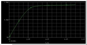
The equation you wrote should be this one instead,
Id = K *((Vgs-Vt)Vds - (Vds^2/2))*(1+L*Vds)
This is the characteristic equation for MOSFET in triode region, while the following one,
Id = K *((Vgs-Vt)^2)*(1+L*Vds)
is the characteristic equation for MOSFET in saturation region. Combining both equation yields the graph attached. In saturation region, where all amplifying MOSFET works in, a small change in voltage leads to a large change in current, hence amplifying.
Attachments
Nelson Pass said:
1) We are mostly using plastics now, but we maintain a stock
of IRF244, IRF9240, and IRF250 in TO-3 cases.
2) Fast rectifiers give better EMI figures, which along with RF
filtering, allows us to pass import regulations in various countries.
Anecdotally, we think they sound better than what we had been
using.
3) It depends on what you consider linear. I have often used
banks of Source-followers without feedback, and the resulting
distortion is quite low, although not as low as you can get with
feedback. The question is - how low did you want it?
😎
If i can, Mr. Pass, i would be curious to ask you the following questions:
speaking of sound characteristics, are these TO-3 devices that you mentioned above, better than the classic Plastic TO-247 IRFP240?
Within the 3 of them that you mentioned before, what is your favourite and, in case there is one, what is/are the reasons?
Thanks.
Given that the TO-3 case is slowly being phased out, the question is moot. The favored piece is the one that's available.
Grey
Grey
The TO-3's are prettier, and they hold up better in corrosive
environments, but that's about it.
😎
environments, but that's about it.
😎
Nelson Pass said:The TO-3's are prettier...
I used to think so, too, but I've gotten to the point where I prefer the look of the plastic case devices.
One thing I never see mentioned is that the newer plastic cases feature three solder connections, whereas the TO-3 cases had either three mechanical connections (assuming a socket) or two solder connections and a mechanical connection (assuming that the base and emitter were soldered, with screws for the case, presumed to be the collector in this instance). I'm always wary of mechanical connections because they can come loose and I have seen them corroded before. No, I've never seen anyone else fret about this sort of thing--it's just me being silly.
Grey
- Status
- Not open for further replies.
- Home
- Amplifiers
- Pass Labs
- X amp considerations