IVX said:
nice if the sound great, by the way, not every professional class D amp can sound even decent (many people tell me, that Powersoft, Crest etc class D purchased for light weight only, but never for the sound), next for the decent THD spec, you need exactly those 6db of loop gain, that you lose in the your current design, with the same part count.
People I talk to say just the opposite. Lightweight is an added bonus.
Hi Fredos,
 proto has just burned...
don't know why
output stage blown (IRFP 240 9240)
with no signal and 9.4 ohms load
output ripple was 2vpp @ 250khz but with high voltage overshoot at every switching
that's a problem of deadtime i think
the values were taken from your model 1200
Vcc is +/-60V
just changed rgate from 4.7 to 10
and REG+ and REG- resistor from 510 to 680 (53ma per amp isn't it ?)
help
amp failed wen i applied 1kHz sinewave low amplitude to input
proto has just burned...don't know why
output stage blown (IRFP 240 9240)
with no signal and 9.4 ohms load
output ripple was 2vpp @ 250khz but with high voltage overshoot at every switching
that's a problem of deadtime i think
the values were taken from your model 1200
Vcc is +/-60V
just changed rgate from 4.7 to 10
and REG+ and REG- resistor from 510 to 680 (53ma per amp isn't it ?)
help
amp failed wen i applied 1kHz sinewave low amplitude to input
Hi
I hope you will put let say 100 ohm or more resistor each in path from supply to amp, for + and -. This will help if something will go wrong next time
I hope you will put let say 100 ohm or more resistor each in path from supply to amp, for + and -. This will help if something will go wrong next time
hi luka !
i used to do that but not this time...
I changed the output stage P N channel fets
but something is wrong with dead time adjustement...
shoothrough burned the 2 fets...
i used to do that but not this time...
I changed the output stage P N channel fets
but something is wrong with dead time adjustement...
shoothrough burned the 2 fets...
Hi
Burned those fets??? That must have been large shoothrough. Hope you will start to use those resistors again until you are sure that it works
Burned those fets??? That must have been large shoothrough. Hope you will start to use those resistors again until you are sure that it works
the 2 fets are dead with a hole in the center of the package...
i suppose this is due to shoothrough
what could it be with a little input signal ?
i need some help to fix this
i suppose this is due to shoothrough
what could it be with a little input signal ?
i need some help to fix this
Hi
Well you had supply voltages coming from other board, that i've eliminated by making those tip50 voltage regs. So you only need main supply voltage and thats it.
Well you had supply voltages coming from other board, that i've eliminated by making those tip50 voltage regs. So you only need main supply voltage and thats it.
Have you exactly follow schematics? I have built over 500 of these amp and never get any probleme with them....Maybe the 10 ohms gate resistor, but I dont think....This should just add more dead time...How was your square wave before it blow? Overshoot? Used 0.47uF MKT between mosfet Source? Zener level shifter was there? You can play a bit with the emiter resistor of the level shifter to play with dead time (R13 and 14 I think...Dont have schematic with me... By the way, I use Litz wire for output coil... Better result everywhere...Maybe this?
Fredos
Fredos
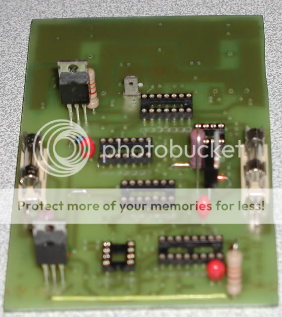
Hum....Did see your MKT decoupling cap on your picture! C1 and C2 on schematics! That's your mistake!
Fredos
Fredos
Hi Fredos,
Thanks for your answer but what caps are you talking about ?
C1 and C2 aren't decoupling caps...
MKT aren't suitable for decoupling with such frequencies ?
Got one 1uF cap in the input path (blue one) (high pass filter with 10Hz -3dB frequency ) and the other is part of the triangle wave integrator (yellow one 4.7nF) but I used these ones with the previous proto wit no problem...triangle wave is clean...
And for the MKT at the input, at worst it has an impact on the sound quality but not on amp reliability ?
Could you tell more about the dead time adjustement ?
would it be good to replace R13 and R14 with variable resistor to set DT easily ?
Dead time control module is here to provide more dead time when output is low isn'it ? by increasing emitter current no ?
At the output of your module at idle you have a clean sinewave @250Khz with ~2Vpp ? do you see switching spikes on it ?
before it blew i saw such 20V spikes at each switching...
I forgot i didn't have 0.47uf between sources, the orange one you see is part of the zobel network (10 ohms + 220nF)
The output filter cap isn't good ? 0.47uF MKP 600V ?
Hi Fredos,
i've just disconnected output stage and i'm making some measurements on the modulator and level shifter.
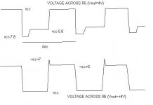
for the upper stage of the level shifter i measure 5,93V across R5 680ohms is it enough tu turn the upper fet on ?
ie half time 60v half time 54,07V
on the lower side i measure 4,93V across R6 ?!
ie half time -60V half time -55,07V
maybe fets burned because they were in linear mode and not saturated...
i've tested adaptative dead time:
with 0v at the output : 50% square wave across R5,R6 (680)
with 6V at the output : 0% square wave across R5,R6 (680)
don't understand how it could work like this fredos
could you tell me more ?
thanks for all ;-)
i've just disconnected output stage and i'm making some measurements on the modulator and level shifter.
for the upper stage of the level shifter i measure 5,93V across R5 680ohms is it enough tu turn the upper fet on ?
ie half time 60v half time 54,07V
on the lower side i measure 4,93V across R6 ?!
ie half time -60V half time -55,07V
maybe fets burned because they were in linear mode and not saturated...
i've tested adaptative dead time:
with 0v at the output : 50% square wave across R5,R6 (680)
with 6V at the output : 0% square wave across R5,R6 (680)
don't understand how it could work like this fredos
could you tell me more ?
thanks for all ;-)
Sorry Fredos
just understood the way it works
i've injected DC at the output but i dind'nt pay to attention to the feedback loop so duty was changing !
when i disconnect feedback dead time variation appears...so no problem
upper side 5.9V across R5 to drive fets with 0V output
upper side 7.8V across R5 to drive fets with 16V output
lower side 5V across R6 to drive fets with 0V output
lower side 7V across R6 to drive fets with -16V output
enough to turn on fets ?
Hi
He means the ones going from +vcc to -vcc and are 0.47uF (C1,C2 on his schematics)
PS: 3 to 4 volts are needed for turning on fet, so with 7v fet is fully opend
He means the ones going from +vcc to -vcc and are 0.47uF (C1,C2 on his schematics)
PS: 3 to 4 volts are needed for turning on fet, so with 7v fet is fully opend
- Status
- Not open for further replies.
- Home
- Amplifiers
- Class D
- D AMP is back !!!