Cheapskate DIY "Genelecs" & some other stuff
Like I already told in my forum introduction, these projects were the reason I joined to this forum. I want to build speakers, preferably as cheap as possible. My wife has some kind of fixation for white Genelecs, and I can't see them as an option. For our home cinema purpose, 8020's are probably too "little" and 8030's are way too expensive (they both are actually). Our room is 6 meters long and 4 meters wide, and the height is 2.6m, TV is mounted on the wall and our couch is next to other end wall. So the distance from the front speakers to ear will be almost 6 meters (when watching a movie).
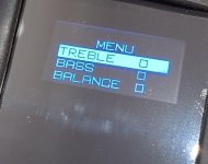
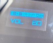
I think we could start from 2.1 system and add other speakers later. Audio quality doesn't have to be as perfect as those Genelecs have, and I'm sure 100dB is more than enough for our needs. Just that those speakers need to look as close to Genelecs as possible (because it fits for our decoration). I can handle that part, but I have no clue about the hardware I should buy...or that if this project is even possible for decent price. I know there are some studio monitors that comes quite close to Genelecs for half the price, so maybe I just buy those and make them new casings 🤔
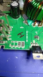
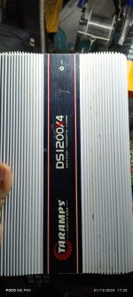
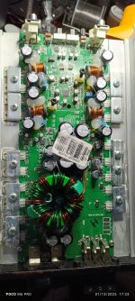
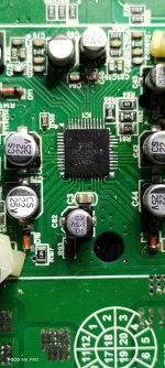
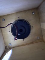
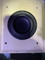
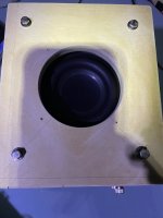
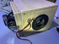
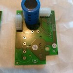
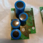
Then another question. I have some old car stereo speakers lying around. JBL and DLE 12" subwoofers, and 5.25" separate system (I think it was DLS...EDIT. No, they were Macrom UNS 5.1). None of them are expensive, but I'm curious if they can be used for anything. How does a car sw work in home theatre if you don't need awfully lot of bass and volume, and what to use as an amp (I have 1 or 2 car amps also)? And how would this separate 5.25 system work as an soundbar (for a gaming console in different room)? Any interesting ideas and suggestions?
I think we could start from 2.1 system and add other speakers later. Audio quality doesn't have to be as perfect as those Genelecs have, and I'm sure 100dB is more than enough for our needs. Just that those speakers need to look as close to Genelecs as possible (because it fits for our decoration). I can handle that part, but I have no clue about the hardware I should buy...or that if this project is even possible for decent price. I know there are some studio monitors that comes quite close to Genelecs for half the price, so maybe I just buy those and make them new casings 🤔
Then another question. I have some old car stereo speakers lying around. JBL and DLE 12" subwoofers, and 5.25" separate system (I think it was DLS...EDIT. No, they were Macrom UNS 5.1). None of them are expensive, but I'm curious if they can be used for anything. How does a car sw work in home theatre if you don't need awfully lot of bass and volume, and what to use as an amp (I have 1 or 2 car amps also)? And how would this separate 5.25 system work as an soundbar (for a gaming console in different room)? Any interesting ideas and suggestions?