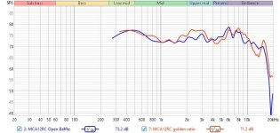
I have a midrange driver (Seas MCA12RC) that I'm experiencing an unwanted dip in response in the 3.5k-5k region which I would like to bring back up, for a flat response. Or looking at it differently it could be interpreted as a peak between 1.5k-3.5k also. I believe its due to standing waves or resonance in the enclosure, because I've measured the driver in an open baffle and it seemed more linear. I'll attach the FR as measured in REW, with a gated window to eliminate room effects. I'm looking for ideas on how to fix it.
The enclosure internal volume is 0.304 cu/ft (8.6L), 13" wide 9" high 4.5" deep. I currently have additional wood panels inside it to make the walls 10.9" wide, 6.75" high, 4.16" deep. Driver is mounted right in the middle. 🤷♂️
I did some analysis and the 4.5" enclosure depth would have a primary resonance wave at F=1125/.375= 3000hz, and a null at 1.5*ƛ=4500hz and 0.5*ƛ=1500hz. All of which correlate with the response I'm measuring. So it would seem that we have both a peak and a trough.
If I analyze the enclosure width, driver in the center, the standing waves should occur at ƛ=0.541/1125=2076hz, and nulls at 1038hz and 3114hz.
What I have tried thus far:
At this point I am entertaining ideas like making non-parallel walls, or turning the interior volume into a tapered quarter wavelength pipe with two closed ends (I don't know if that will work).
Looking for thoughts from experienced enclosure builders.
The enclosure internal volume is 0.304 cu/ft (8.6L), 13" wide 9" high 4.5" deep. I currently have additional wood panels inside it to make the walls 10.9" wide, 6.75" high, 4.16" deep. Driver is mounted right in the middle. 🤷♂️
I did some analysis and the 4.5" enclosure depth would have a primary resonance wave at F=1125/.375= 3000hz, and a null at 1.5*ƛ=4500hz and 0.5*ƛ=1500hz. All of which correlate with the response I'm measuring. So it would seem that we have both a peak and a trough.
If I analyze the enclosure width, driver in the center, the standing waves should occur at ƛ=0.541/1125=2076hz, and nulls at 1038hz and 3114hz.
What I have tried thus far:
- Adjusting acoustical damping materials: Poly fill, Cotton, Rockwool, over stuffing, under stuffing, nothing. Surpisingly, it doesn't change much.
- Adjusting box volume: In an attempt to choose better LxWxH enclosure ratios I've experimented by adding wood to the interior walls to change to a golden ratio. Also surprisingly, it made it worse.
At this point I am entertaining ideas like making non-parallel walls, or turning the interior volume into a tapered quarter wavelength pipe with two closed ends (I don't know if that will work).
Looking for thoughts from experienced enclosure builders.
Attachments

WinISD calculates the box size to be 0.267 cuft (7.5L) for this driver. I will do it over and see if I entered some TS parameters incorrectly. Okay, when I use the manufacturer TS parameters it still recommends 0.267 cu/ft closed, and when I use the TS parameters obtained from my actual driver it recommends 0.214 cu/ft (6.0L). I am open to trying smaller enclosures if that helps because I have this crossed over with a 12" woofer.
Attached impedance plot.
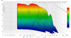
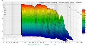
Attaching 1/3 and 1/6th octave burst decay waterfalls.
Attached impedance plot.
Attaching 1/3 and 1/6th octave burst decay waterfalls.
Attachments


That's plausible. Perhaps the open baffle diffraction response was obscuring it before.
I'd also suggest you look elsewhere for the differences, not only in the diffraction response but sometimes a box has resonances that take effect through mechanical conduction to the panels.
As mentioned, a close mic'd measurement may help to show resonances and polar measurements may help to show delayed cabinet effects.
Hmm, eff dia = (55*4/pi)^0.5 = ~8.37 cm; 1/2 WL standing wave = 34400/2/900 = ~19.11 cm, so how does a surround generate a ~19.11/2 = ~8.37 cm 1/4 WL? Reflection off a very hard dustcap instead?I just tested that and yes I get that 900hz blip there as well.
From what I understand that is related to the rubber surround.
Why would you use WinISD for a midrange? You’re not planning to use it at fc are you?WinISD calculates the box size to be 0.267 cuft (7.5L) for this driver.
The ridges in the burst decay plots aren’t resonances btw. I think your only resonance issue is at bespoke 900Hz. Which wavelength fits very nicely in 13” or 10.9” (speed of sound slows down in dampened cavities) plus you mounted the driver in the middle, and the standing wave is therefore pressing hard on the cone.
Last edited:
Thanks!Some good investigation GM. Just a thought, could it be a mass/compliance resonance?
Could be, but dismissed it since the surround would need to be paper thin to show up at a measurement's tiny power, which in turn would ripple pretty bad at higher powers like those early high power/Xmax (sub) woofers use to (still?) do.
Not a lot of unexpected behavior based on other measurements, just the effects are more pronounced as your measurements are less smoothed.
https://www.dibirama.it/home-page/mid-range/365-seas-mca12rc-mid-range-4-8-ohm-400-wmax.html
https://www.dibirama.it/home-page/mid-range/365-seas-mca12rc-mid-range-4-8-ohm-400-wmax.html
No, it will be band passed well above the Fc, I just used it because it was handy to calculate the volume for a QTS of 0.707. How do you prefer to determine your enclosure volumes?Why would you use WinISD for a midrange? You’re not planning to use it at fc are you?
The ridges in the burst decay plots aren’t resonances btw. I think your only resonance issue is at bespoke 900Hz. Which wavelength fits very nicely in 13” or 10.9” (speed of sound slows down in dampened cavities) plus you mounted the driver in the middle, and the standing wave is therefore pressing hard on the cone.
A 2L enclosure would yield a QTS of 0.945, wouldn't it affect the transient response? I was under the impression that the flattest midranges had larger enclosures and were stuffed heavily.
Yes, I see how the height is exactly twice the depth and that is unfortunate because the fundamental of one will constructively interfere with the 2nd harmonic of the other. I am considering building a test enclosure to see if I can get a flatter response, or learn something more about what is going on.
I am not sure the speed of sound changes in damped cavities.
You refer to Qtc. The Q of a resonant system only applies to the resonance (a small range around fc) used for the natural highpass of the system. Since you will probably cross a few 100Hz above the fc, the midrange won’t play in that resonant range. So targeting at some Q at a certain f and next applying a highpass well above the same f makes little sense, other than needing a certain impedance behavior to make a passive highpass possible. But that would be easily solved by using a notch in the crossover.
The huge disadvantage of big mid enclosures is that resonances (standing waves) occur at lower frequencies, mainly in the passband of the system. Those resonances tend to leak through the cone and color the sound. So in fact you presented yourself with a poser by using an unnecessary large enclosure. There’s another disadvantage: big enclosures have big size walls that will resonate and produce yet more unwanted sound output. In the midrange that is. Simple rule of more area = more radiation. Last disadvantage: you need more construction material. And yes, sound of speed slows down in sound absorbing stuff.
The huge disadvantage of big mid enclosures is that resonances (standing waves) occur at lower frequencies, mainly in the passband of the system. Those resonances tend to leak through the cone and color the sound. So in fact you presented yourself with a poser by using an unnecessary large enclosure. There’s another disadvantage: big enclosures have big size walls that will resonate and produce yet more unwanted sound output. In the midrange that is. Simple rule of more area = more radiation. Last disadvantage: you need more construction material. And yes, sound of speed slows down in sound absorbing stuff.
Just did that and get the same result. I'm thinking the blip at 900hz is a red herring and attributing it to something intrinsic with the driver since it appears in both the open baffle and the enclosure, regardless of type of damping.I'd stuff the cabinet with poly wadding or similar, then remeasure impedance.
Arez makes a good observation that the FR chart at Dibirama.it shows the same characteristic peak at 2.5khz and smile shaped dip at 3khz-6khz. And I assume they measure that on an infinite baffle, which wouldn't have standing waves. This supports Markbakk's opinion they aren't actually resonances.
Still the factory FR chart shows a peak to trough range of only 3db and I measure it at 6db. Adjusting the graph from 1/24th smoothing to 1/3rd smoothing indeed does change the apparent peak to trough to 4db now. So, it would appear that there aren't any glaring issues, but that means I am back at square one trying to flatten out the response, and will have to address it in the crossover.
Thanks for that insight Markbakk, I think I will make a test box tomorrow addressing all the tips covered and measure that to see if there is any change and see how it sounds.
The key things I will change are:
The key things I will change are:
- Use a smaller volume, e.g. 2L
- Non-parallel walls
- Driver mounted off center, e.g. 40% of baffle width.
- Enclosure depth being the longest dimension.
- Home
- Loudspeakers
- Multi-Way
- Help with sealed enclosure, midrange response, standing waves