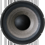
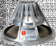
Sealed midrange/midbass too damped??

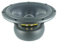
I have a Ciare HWG 160-4ohm that is really more suited in a vented enclosure.
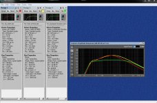
I have a 3 way cabinet design that has a sealed mid chamber of only .275 cf after all displacements (including this speaker). My question is is this going to be too damped in this small enclosure? Calculator is showing about .95 cf for sealed alignment of .707. Since the Qts is lower than the Qtc and the xmax is not too small I think it will work but just looking for opinions. I tried to model this driver on winisd but did not work will, the frequency curve was way off(not even close to linear) from what the manufacturer shows which is very flat +-3db!!

I will probably be crossing to allow usable frequencies of 200 Hz to 2k Hz. I am using a dsp with a few different crossover options so it's easy for me to play around with different xover points.
I am using a Morel CAT378 Tweeter and still playing around with
8" bass drivers, not a giant fan of Dayton but they have an 8" sub( RSS210HO-8) that
will tune flat to around 34 Hz in a 1 cf enclosure, which is what I have in
my cabinet...not as low as what I would like but my project started off very small and now it is twice as large as I was hoping!! 😱Why can't I fit a 3" x 60" port into a matchbook😱 :drunk: PLEASE PARDON MY TANGENT:drunk:

Folded cascode lateral MOSFET power amp

I am fond of the lateral mosfet OPS power amps and after building two successful examples:
Assemblage Power Amp

and the bigger lin type:

Very HQ power amplifier (Assemblage VII)

I want to build another one with hopefully even better high frequency response.

Recently read this paper by Bob Cordell http://www.cordellaudio.com/JFETs/LSK489appnote.pdf
where I found a DOPA using a folded cascode IPS and decided this would be a good start for my new power amp.

Allready simulated one possibility but have some doubts about it's viability.

My sim indicates this design is stable even without compensation.....
I can not reduce 1khz distortion below 0.015% THD....
I am not sure about the best ccs to use for the folded cascode IPS....

Hope my design captures enough interest and discussion so I can improve this solution.

Please find the schematic and asc file in attach

Best
Ricardo

Attachments

Looking for Alps switch (for Accuphase preamp)

Hi everybody,

I'm desperately looking for a replacement part for an Accuphase C-200V preamp - a tape input/output selector switch, which is no longer available from Accuphase or its authorized distributor in Germany.

It's an Alps rotary switch, 1 pole, 5 positions, 18 tooth serration.

The Alps part no from the current catalog is SRBM150500.

It is impossible (for me) to source this component in Germany, but it might be quite easy in other parts of the world. Maybe someone even has such a switch in his junk box. Please drop me a line if you can help!

Thank you 🙂

Attachments

  • srbm_l.gif
    srbm_l.gif
    6.5 KB · Views: 332

FS pair of GAUSS CETEC 4081 2" compression drivers

This is your chance to own a pair of GAUSS CETEC 4081 2" compression drivers.
These are in nearly new internal condition, the diaphragms are in pristine condition and are phenolic, 4 1/8 inch. 8Ω , 119dB, 300-12000Hz, 17kgr monsters. These are rare as hens teeth and fabulous sounding devices!:redhot:

Yes in the first pic it is the one on the right, the biggest one...24cm in diameter and 15cm height.

Attachments

  • 89567075_10219062286722536_3945440997730680832_n.jpg
    89567075_10219062286722536_3945440997730680832_n.jpg
    31.4 KB · Views: 244
  • 88434821_10219056891027647_3698456760185520128_n.jpg
    88434821_10219056891027647_3698456760185520128_n.jpg
    74.7 KB · Views: 242
  • 89438018_10219056890227627_3500459631128346624_n.jpg
    89438018_10219056890227627_3500459631128346624_n.jpg
    87.9 KB · Views: 247
  • 89394507_10219056891107649_340620202544726016_n.jpg
    89394507_10219056891107649_340620202544726016_n.jpg
    97.2 KB · Views: 226

SpeakerPower Torpedo SP1-4000 Plate Amp Review

Brian Oppegaard, President of SpeakerPower sent me one of his Torpedo SP1-4000 amps for evaluation. Brian spent 11 years as Director of Engineering at QSC Audio Products, Inc. and seven years in the same capacity at Renkus-Heinz before starting Speaker Power in 2002.

SpeakerPower has a wide variety of “plate” amps for use in powered speakers.
The SP-4000 is presently their most powerful amp, and the first amp in which the company makes every circuit board used.

SpeakerPower - Home

The amp is rated 4000W/2 ohm, 2400W/4, 1300W/8, it weighs only 7 lbs.
Front panel has one input, a balanced XLR input with a looping XLR output.
One detented volume control, two push switches, one selects full range response or a 30-80 Hz sub filter, the other a polarity reversal.
A Powercon locking AC input, and a Speakon locking looping speaker output complete the “user interface”. The internal speakers are connected with a latching polarized six pin connector.

The amp itself takes up very little internal volume in a speaker cabinet, and produces almost no heat, critical features for a powered speaker amplifier.

When compared to other amps, the lack of heat produced by the 90-95% efficient SP-4000 was striking. The cool operation also uses less power from the AC power service, very important when using the amp with marginal power. More power delivered to the speakers with less from the wall is not only green, but louder!

So how loud does it go, how does it sound ?

Sounds just like the signal going in, until the clip light goes on. Even after the clip light goes on, very little change in sound quality, the clip light is tied to a very fast limiter. Pushing the amp another 6 dB harder after the clip light illuminates, little harsh clipping sound was generated.
This could actually be a problem for some users who will crank the input until high average power smokes the speakers, since there is very little audible tell tale clipping sound.

The SP-4000 has enough power to cause thermal compression with a pair of Eminence Lab 12 six ohm speakers in a matter of minutes using band limited pink noise run just up to clip. Speaker tests were done with both horn and bass reflex cabinets.
Pink noise has a crest factor of 12 dB, more than some heavy duty compressed dance music, users may exceed the average level of pink noise.
The amp did not heat up even with a nominal 1.5 ohm load, but the speakers sure did!
Without some external limiting to keep average power in check, the SP1-4000 does have enough juice to burn speakers in the 400-700 watt continuous range.

So the amp was able to make the Eminence Lab 12s and a 4015LF sound distressed when hit hard, what about “big gun” speakers?

Just about the time the amp arrived for evaluation I was testing new cabinet designs for the B&C BC18SW115-4, a four ohm 18 inch speaker that handles 1500 watts with around 15 mm Xmax.

I used the SP-4000 for much of the speaker testing, it was nice to not have a noisy fan blowing heat into the shop while the speaker was getting the equivalent power of a space heater.

The BC18SW115-4 speaker could probably take every watt the amp could produce without a strain, so from a “bullet proof” powered speaker application, the amp would be a good choice.
That said, for operators that wish to take advantage of the huge peak potential of the latest crop of super speakers, more power could be used.

Brian is working on an export/high mains voltage version of the SP1-4000 which will do 110 V in to 2 ohms, 6000 watts, using a buck regulator to reduce 180-240 VAC mains to a 190 VDC rail for the amplifier. The SP-4000 has a 170 VDC nominal rail.

Power of the high mains voltage version will be approximately 2000W/8, 4000W/4, 6000W/2. The 2 ohm number is tentative and depends on AC line voltage and quality.

This will also apply to the SP1-2400. At higher mains voltages it will do 2000W/8 4000W/4, but no 2 ohm rating.

Brian is also kicking around the idea of doing a 100-120VAC boost regulator version which will do the same numbers.

He asked me if people will pay the extra $100 or so for the higher power.
I can only answer for myself, if using speakers in the power range of the BC18SW115-4, definitely yes.

Having looked at trends in speakers and amps as they chase each other’s power ratings for almost four decades now, I think the new crop of speakers that can handle 1500 (real) watts and peaks of 3 to 6K will only grow larger, a super power plate amp will be welcome.

Using music and pink noise I tested the SP-4000 against all the amps in house, a Crest CC2800, a Crest CA-9, an old Crown PSA 2 (weighs 8 times more than the SP-4000 !) and a QSC PLX-3602.

All the rack amps are capable of 4 ohm bridged mono operation, so a single four ohm load was used.

With music and pink noise into a BC18SW115-4 loaded bass reflex speaker, the Torpedo equaled the SPL output of the CA-9 and the PLX 3602 (though one 3602 died during testing) put out about 4 dB more than the PSA 2, and 5 dB more than the CC-2800.

Notably, when the SP-4000 was loaded at two ohms, (one speaker and a dummy load) the speaker level only dropped by 1 dB.
None of the other amps could put out as much level as the SP-4000 driving two four ohm loads.
As it stands, the SP-4000 is the highest power commercially available plate amp I know of.

Art Welter

The Leach Amp

I am looking for some opinions....

I recently acquired a commercial Leach amp: The Leach Amp manufactured by LSR&D back in the 80's. It is based on the Leach Low TIM amp design. The specs are fairly impressive, and the power supply is massive. I have had the opportunity to listen to a Leach Double Barrelled amp in a fairly high end system and was impressed with the sound. Listening to this amp for a short period left me disappointed. The sound was veiled and undetailed. The sound stage was almost non existent.

I am driving a pair of Martin Logan Aerius electrostats, but it shouldn't be a problem for the amp. My source is a McCormack CDP and a Curcio Daniel pre amp. My system amp is a Radford ESA225 tube amp (25 wpc Class A) and the basis of my comparison.

So, are the Leach and Radford in two different classes and should I move on in my quest for better sound? Could the Leach be out of spec (it seems to have had a hard life before coming to me!).

Comments and suggestions welcome.

thanks,

Paul

Lenovo Ideapad Z580 Parts/Repair

I have a (non-working) Lenovo Ideapad Z580 15" laptop running Win7. I pulled it out of storage in response to THIS thread. I messed around with it for a couple hours today and seen some sign of life (lights came on), then nothing. It seems a shame to throw it in the trash, but that's where it's going soon. Your's for the cost of shipping. I may advertise it for free locally as well.

Componment placement

I'm just building an input selector / RCA - balanced convertor.

The case is quite tight but it does all fit.

Should I mount the meagre mains transformer at the front of the case away from the XLR connectors or just leave it where it is ?

I don't really want any more holes in the chassis than absolutely necessary.

Attachments

  • 20200422_150837.jpg
    20200422_150837.jpg
    472.1 KB · Views: 240

filling countersunk screws prior to veneer

I am an experienced in wood working, but I have mostly worked with solid wood. When I have used veneer, it is in the form of veneer plywood... used for table-tops and as the panel in frame-panel cabinet doors. Speaker construction is somewhat different than normal cabinetry (obviously).

I am planning a project using 20mm (3/4 inch) Baltic birch plywood, and there will be many countersunk screws on the outside of the cabinet due to the bracing. Before I veneer the outside of the cabinet, I assume I must fill those screw holes and sand flush so that the veneer has a smooth flat face to bond to. I am using peel-and-stick veneer.

What is the recommended filling material? spackling compound (used in gypsum board / drywall construction)? automotive "bondo" body putty? I can think of several materials which might work, but what is the best practice ?

Jim

Upgrade for old RCF N479 compression drivers?

I have 2 pairs of older EAW DS123Hi speakers that are being used as front and center channels in my home theater.

They use RCF N479 (EAW CD2520) 1" compression drivers with phenolic diaphragms, and they seem to quickly roll off the treble around 13Khz. My Yamaha preamp always turns the treble way up when I use the YPAO auto setup mic. These were used commercially before I got them, so I'm not surprised that the tweeters seem tired.

It looks like I might be able to use the B&C DE250, and mount with 2 of the 4 holes, but I'm not sure. If anyone has any other suggestions it would really help. I also see a couple models by Celestion, Peerless and LaVoce that might fit.

These speakers also have new midrange drivers made by B&C, model 6/033B-8. That's one of the reasons I was leaning towards a compression driver of the same brand.

Another option I considered was putting aftermarket titanium diaphragms on the existing magnets, but I wasn't sure how well those work.

I normally get my speakers from Parts Express, so I'd prefer it to be something they carry.

Dead TDA7297 ?

Hello
I just salvaged this IC and tried making this circuit :


TDA7297 Audio IC - Electronic Circuits, TV Schematics, Audio


However only output 2+ (pin 15) works and the sound is very very low, very distorted. Is the IC dead or did I make a mistake somewhere, is there a way to test the IC ?
Current is about 0.1A. Signal ground and Power ground is connected.

Thanks

Caps, Caps & more Caps (Juniper, Russian PIO, Rike Audio, more)

I am cleaning out my capacitor supply. Many of these caps are new and the rest are used but in working order. 10 day money back guarantee (less shipping).

PRICE: Make me an offer on individual caps, multiple caps or the whole lot.

here is what I have (quantity x description)

14 x Russian PIO 50uF 1000V (1KV) (large brown box w/ white terminals)
10 x Russian PIO 30uF 160V (brown box)
4 x Russian PIO K75-10 2.2uF 250V (green small)
2 x Russian PIO K75-10 10uF 250V (green large)
8 x Russian PIO K40Y 0.47uF 600V (silver)
2 x Arcotronics MKP 5uF 1200V
6 x Juniper Copper Foil Paper & Wax 0.47uF 600V
8 x Mojo Dijon 0.47uF 630V (yellow)
1 x WIMA FKP 4 1uF 1000V
1 x WIMA MKP 4 DC Link 20uF 1100V
4 x WIMA MKP 10 4.7uF 400V
2 x WIMA MKP 4 1uF 1000V
4 x WIMA MKP 4 4.7uF 400V
2 x WIMA MKP 4 2.2uF 100V
2 x Rike Audio Audio S-Cap 0.068uF 600V
2 x Rike Audio Audio S-Cap 0.033uF 600V

Attachments

  • IMG_0905.jpg
    IMG_0905.jpg
    473.3 KB · Views: 262
  • Screen Shot 2020-04-17 at 7.52.25 AM.jpg
    Screen Shot 2020-04-17 at 7.52.25 AM.jpg
    95.4 KB · Views: 255

F4 PS hum ?

Built a pair of F4's paralleled as monoblocks. Lots of time on my hands these days (ha!) -

They are killer -- almost imperceptibly less transparent than my OTL's - and those take a massive amount of power (and money) to run. Quicker than my OTL's, not as liquid as my SE amps -- but more far slam than them, even with 25W (solid state watts, which ARE different)......

Hey, this wasn't meant to be a review......sorry.

Got a small (teeny - tiny) hum from one of the monoblocks, only noticeable at close range to my Lowthers - (not with my other speakers).

hey, we all know how sensitive Lowthers are -- and I've got a choice, since I'm assuming there's a less than perfect PS cap in there somewhere. Anyone think it could be something else? (bad ground?)

I can swap 'em all out, or just forget it. I'm anal, and like I said, got lots of time on my hands these days. Once the music's playing, at any level, you can't hear it.

What would you do?

creative soundworks 740 screen parts /replace

hey all

i have the creative soundworks 740 cd radio , the display has gone dim on one side only

ive broken it down so far in the hopes i can fix it

a,would this screen be custom to the unit or likley i can source a replacement ?

b, are there any replacable parts inside the black screen ?

An externally hosted image should be here but it was not working when we last tested it.


An externally hosted image should be here but it was not working when we last tested it.


any help apreciated

STK to TDA7293 conversion

Hello everyone,
I have an AKAI amplifier that one of the channels has stopped working, one of the STK082 is shorted, I thought about replacing the STK082 but the price for the original part is too high... and I am not sure if using a non-original part is good idea... So I thought about converting the two channels to two TDA7293.

I am thinking of removing all the components that are not needed (selected zone), since they can possibly create some kind of problem...

Any recommendations?

Attachments

  • Akai-AM-2350.jpg
    Akai-AM-2350.jpg
    1,006.2 KB · Views: 440
  • Board TDA.jpg
    Board TDA.jpg
    97.5 KB · Views: 410

ncore amp build, loud hum noise

Hi,

I just built my new amp yesterday, using a nc122mp module and a ghent audio case.

When I first powered on the amp, I got a very loud hum in the speakers. (>10m audible)
As soon as the preamp was turn on, no more hum noise.
Then I tested the amp alone (without any xlr plugged in, only speakers out) and still had the noise.

So I once again checked my solders, and notice a little lug on the xlr socket, near the pin 1.


After some readings, I decided to solder the pin 1 with this chassis lug, and the noise mostly disappeared, when no XLR cable is plugged.
If I plug the XLR cable again, the noise is back, and if I "move" the xlr cable, the noise changes.

Now, I've a few questions:

  • when I compare with same ncore/ghent audio builts pictures on the net, nobody solder the pin 1 with the chassis lug. Is it needed ?
  • I used thermal compound between the case and ncore module (not the full area). Maybe it "breaks" the ground connection, so it's why I needed to solder pin1 with chassis lug ?
  • when reading the "Legacy pin 1 problems" whitepaper on hypex site, I understand the good solution is to solder the pin 1 to chassis, and no connection between audio circuit and pin1.
    But in the ghent audio case kit, the pin 1 should be soldered to J4.3 and J4.14 (GND).
    Do I need to bypass it, and only connect pin 1 to socket ground lug ?
  • Do I need to soldier pin1 to chassis lug in the XLR cables too ?
Thanks for your help

Support for high samplerates in SW analyzers

After a few patches the RPI4 USB audio class 2 gadget supports the maximum 1024bytes packets size in USB2 microframe (i.e. 8000 x 1024 bytes = 65Mbits/s duplex throughput) now. Good opportunity to test how common software analyzers deal with high samplerates.

Tested in linux which accepts any samplerate reported by the USB audio device. I configured the gadget to use 1536kHz/24bit/1ch (36.9Mbits/s), with sox generating 700kHz sine signal on the RPi. The USB host was capturing from the USB gadget and analyzing .

Arta in wine - fixed samplerate at 192kHz, not working

REW - not tested yet but definitely will require low-latency garbage collector of the latest java.

Audacity - while it accepts files with any samplerate (I have tested 10MHz files), its soundcard backend is limited by portaudio samplerate range, probably could be changed and recompiled. Stock version not working.


VisualAnalyzer in wine - did not offer the device samplerate, but could be configured at any samplerate. Would require some work (from its author as it is not open source) but its potential is quite good. Screenshot taken.


jaaa - a simple open source FFT analyzer in linux, works OK. Unfortunately only 128k FFT length which is quite little. But this could be changed in the source code. Screenshot taken.

Attachments

  • va.png
    va.png
    107 KB · Views: 481
  • jaaa.png
    jaaa.png
    39.6 KB · Views: 495

Pioneer SA-1040 Amplifier Relay Not Clicking :(

Hi,

I'm all new to this forum hoping for some help with me trusty amp.
I bought this amplifier from Dubai where they have 220 Volts with 50Hz cycles, but i'm now moved back to Canada where it's 110V with 60Hz cycles electricity.The unit does have the voltage selector to select the voltage like 220V-240V and 110V-120V and i'm using 110V-120V.

For some reason when i turn on the unit, it turns ON with all the lights etc but it's the Speaker protection Relay is not Clicking (not completing the circuit to pass the current).

Is the because of the more Voltage Hz cycles as it was made to get 50Hz but here in Canada it's 60Hz or is the Relay unit itself which is now faulty for no reason all of the sudden ? I could be wrong but the unit was working perfectly fine in Dubai before i moved back. I have attached the pictures of the circuit and the Relay as well as the the service manual with diagram.

Your time and help would be appreciated.

Service Manual Link :
Pioneer SA-1040 - Google Drive

1YADaSy.jpg

rgNl6Xx.jpg

New Member

Hallo forum members,

My name is Paco and I live on Aruba since 2003.
I have started a Pro Sound rental & sales company in 2015 and I build speaker systems for almost 30 years.

It's a pleasure to be a member of such a large database forum full with amazing projects and knowledge!!

I hope to do my share to this forum!

Have a wonderful day!

Crossover issue (I think)

I am novice/beginner speaker builder.
I have built a subwoofer with built in amp and a pair of 2 way bookshelf speakers. I followed a YouTube video for the sub so those components should be ok.
Here are all of the components I used:
Subwoofer - Tang Band W5-1138SMF 5-1/4" Paper Cone Subwoofer Speaker
Amp - TPS3116D2 Class D 2.1 Bluetooth 5.0 Amplifier Board 2 x 50W + 100W with Filter and Volume Controls
Tweeters - Peerless by Tymphany BC25SC06-04 1" Textile Dome Tweeter
Midrange driver - Dayton Audio RS100-4 4" Reference Full-Range Driver 4 Ohm
Pre built crossover - Dayton Audio XO2W-4.5K 2-Way Speaker Crossover 4,500 Hz

My issue is over powering bass both from the subwoofer and from the speakers/drivers (the larger issue is the overpowering bass on the drivers because I can turn down the sub channel bass on the amp). I have an old pair of one way speakers and when plugged into the amp the bass is not overpowering in either the subwoofer or speakers. This is why I am assuming it is the crossover that is causing my issue. Should I have used a woofer and a tweeter with this crossover is stead of a mid range? Are you not supposed to use crossovers with midrange driver? Is this the wrong crossover to use? ( I chose a crossover with the highest frequency so it would give more range to the driver) The two channels are 50 watts and the wattage needed for both tweeter and driver is 50 is this ok? Thanks.

How can I filter heavy gramophone noise?

I have a set of audio files rescued from a source of phonograph record like a gramophone. Very old family stuff records from my elders back in year 1946. A relative has digitalized these with a turntable and gave the records to me in lossless WAV Format. The audios are just conversations of my relatives in cotidiane situations. So it is just vocals materials but mixed with a heavy quantity of noise. Noise is mostly concentrated in the mid-high frequencies, like 1Khz-10Khz. So the records are VERY noisy. SNR is like 0dB or worst. My mission is to filter out the noise.
One advantage is that noise exhibits a cyclical pattern. I tried some classic vinyl restoration stuff like decracking o declicking with Sound Forge, DART 24 Pro. Results were unsuccessful. The best result I had is the "Noise reduction" effect in Audacity, which did output relatively good. But this last one just filters the frequencies where the noise is with narrow FFT. So the vocals content loses the high-mid frequencies. Leaving only mid or mid-bass content. The noise got down but voices are unintelligible.
So I think perhaps I could turn to a Artificial Intelligence solution?. but I have no clue from where can I start. I have some understading of theory of AI, the Perceptron, neural networks, Backpropagation, but I never applied them to audio. Perhaps a Convolution Neural network could be a solution, but how could I train it?. If helps, I have programming skills in C# and knowledge about digital linear filters like IIR and FIR. But equalization based solutions *are not, what I need *.
Below I offer an example track for your consideration.


Pista de CD 3.wav - Google Drive


What can I do for filter this kind of cyclical pattern noise?

BGW 750C popping the combination fuse on/off switch

Just acquired this amp last night for a project. Was told that the amp had a low power symptom but to no surprise it pops the combination fuse breaker and on off switch. It was powered up using a light bulb on the power cord. Bulb was bright.

The right channel has newer outputs MJ15023/MJ15022. Appears to be an older replacement. Doesn't appear to have anything smoked.

Advice?

Attachments

  • 20160122_065126-1024x1820.jpg
    20160122_065126-1024x1820.jpg
    482.4 KB · Views: 232
  • 20160122_065153-1280x720.jpg
    20160122_065153-1280x720.jpg
    218.2 KB · Views: 228

Technics SA-DA10 overload and now spkr relays dont turn on

Hello Everyone,

I am new to this forum and I have found some good advice and information already on troubleshooting my technics amps for this OVERLOAD condition. It was mostly other models but it looked like they shared a lot of the same components and design so I was mostly extrapolating to understand how the different circuits worked and tried to apply it to mine.

I did manage to get my hands on the service manual for this specific model so I have some schematics and some voltages to check. Although I am a bit confused as to what the voltages are in reference to. I checked both chassis ground and points that the power modules (IC601,602,651) are connected to on Pin8 (gnd). I figure that's probably the gnd I should be referencing, but I could be wrong.

I was able to find that the common cause of OVERLOAD was either:
1. cooling fan not working
2. cooling fan circuit faulty
3. shorted spkr terms
4. DC offset on output lines (pins 3 and 6 of power modules)

What I have done so far:
1. Tested fan with a 12v battery and it turns on so that seems to work. It's a brushless DC I believe.
2. haven't checked the cooling fan circuit yet as I don't have proper probes to reach all the little tiny spaces where the transistors are and dont want to accidentally short anything out while it's ON.
3. Spkr terms are not shorted - spkrs aren't even connected. The terms measure 20-30kOhm between +and - of each terminal.
4. I wasn't able to find a DC offset, if I measure between pin 3 and 8, and 6 and 8 of the power modules (IC601/602/651).

I read about the solder joints and how they can become bad over time due to heat and board stress. Since the OL would come on after some time of being ON (no spkrs connected and in tuner mode), when it did go into OL, I pushed on the heatsink and the spkA relay would click back on as well as the fan turn on briefly (about 1 sec) and then turn back off and the relay clicked back off). Definitely seemed like a solder joint. The IC602 was replaced under warranty years ago and I could tell the solder points were different and pretty healthy. I re-did some of the joints on IC601, and same problem. I suspected it might be faulty based on what I had read so I pulled it out and tested with 601 missing.

The OL didn’t come back after the amp was on for some time, no spks connected, and in tuner mode like before. Since all power modules are the same number I thought I would try the 651 chip (center channel) in the 601 place to see if it really did go away. I soldered it into place and turned it on and no OL. However at this point, the spkr relays don’t click on. It didn’t click on before either but I figured that was because the 601 was missing and pin 15 seems to drive that output. I then noticed on the schematic that Q651, Q652, and Q653 look like they all need to be triggered to close the relay drive circuit to ground (I could be totally wrong here in my assessment). So, I installed the ‘suspect’ IC back in the place of the IC651 location to see what would happen. Well, OVERLOAD doesn’t appear but the relays still don’t click on. I am not sure if I maybe damaged something else in the process, which is possible, although I am generally pretty careful with stuff like this and haven’t blown any circuit boards yet.

If anyone has a good method to go about troubleshooting this problem that would be amazing. I would love to get any input on this or ideas on what to check and what to expect to see. Im at a point where I don’t really know where to beginning or what to check anymore.

Thanks in advance,

Power Requirements

I'm not sure if this is the correct form for my question but it deals with a multi way speaker. I have an amp with 50 watt channels and I have a pair of two way speakers consisting of a full range driver and a tweeter. The full range driver requires 30 watts of power and the tweeter requires 20 watts of power. I added the values together for my amp to get 50 watts. Should I have not done this? Are both my speakers over powered or powered correctly? Thanks!

What electric car to buy for my kids?

Hello,

I've been looking to buy an electric car for my kids. Hopefully a new learning experience for them. But i literally can't decide on which car to buy for them . It has been a difficult decision to make for a mere electric toy car. Driving a car is an wonderful and important combination of responsibility and pleasure for the kids. To do this at such an early age would hopefully help them grow better. But a car that is safe for the kids without obstructing their learning is hard to find. The electric car will also help them understand how they can protect environment at a young age.Here are my top 2 choices for thr future purchase , please help me with this decision. Also , if you have any new suggestions feel free to recommend .

1. Power Wheels Dune Racer

Key Features.
Two driving modes in the forward direction- 2.5MPH and 5 MPH.
Power Lock Braking System.
Monster Traction system helps in driving even on Wet grass and Rough Terrain.
2.5MPH in Reverse direction.
Storage area under the hood for other toys.
1 Year warranty for the car.
6 Month warranty for the 12V Battery.


2. Peg Perego John Deere Ground Force Tractor with Trailer

Key Features.
2 speeds (2.5MPH and 4.5MPH) plus an additional reverse mode with speed-lock technology.
Adjustable seat with armrests.
High Traction Farm Tyres for better grip on different surfaces.
In-built FM Radio
Light Weight Body
Full size-Detachable Trailer
Free second-year warranty.

Powered Monitor Amp and Power Supply/Repair Upgrade

Hey People

Hope your all well!

Thanks for all the great info, learned a lot here over the last few years. First post so any assistance greatly appreciated! Hope its in the best thread?

Repairing/Upgrading amps in my ADAM S2.5A powered studio monitors. Still sounding amazing and mostly working well, feeling they have lost some definition over their 15 years of good use. Would really appreciate some advice so apologies about the many (sometimes lacking in knowledge) questions below!

One speaker repeatedly clicks when tuning off, the other clicks once. Could the be the C5468 Transistors (found some very close replacements, only difference in specs is Pd of 500mw vs 625mw on originals, is that an issue?

On inspection one of the power supply storage caps felt loose, desoldered and better but probably the snap-in on the actual cap is loose. Hot glued in place until I can find some good replacements, haven't tested yet.
There are 2 installed and 4 spaces, would there be any point replacing the 2 10,000uf 50v's with 4 suitable caps, or best stick to the 2? some 380LX103M050J052 from Mouser will fit nicely (381 too wide).

Will do all caps on all boards (smaller caps on power board done).

What else to upgrade or replace with new on the amp board?
Any point doing resistors after 15 years? The big green ones are marked 0R10 5W 5%, .1 ohm yeah? Maybe some Mundorf MOX replacements?
Do transistors degrade much over time? Have some On Semi 5200/1943 in stock, should be ok to match pairs on both speakers.
MJE 340 and MJE 15030, well out of my knowledge spectrum as to worth of replacing/upgrading these..

Crossover/EQ/Protection Board. NE5532, a bunch of there there, replace with fresh 5532's (if so best brand?).
Flim caps, all the Whima and Visays I have are branded and nothing on these guys so maybe worth upgrading?

Flim resistors to SUSUMU RS? Put some in a Resonance circuit of a very nicely build synth (Vermona) and did improve stability and creamy sound quality.

Also feeling it would be good experience to do a few parts at a time to learn more about what difference I get from each upgrade. Either that or just get it done and get back to writing music!

Thanks for reading 🙂

Cheers

Hugo

Genesis Stealth Amp

Got a request from a friend of a friend about a dead Genesis Stealth amp. Can't seem to find any real info about it, other than it takes a bloody forklift to move it. :xeye:

Honestly, I have to turn him down as far as helping to fix it unless I can get at least a schematic, or preferrably a service manual.

Anyone know anything about this amp? Is it possible to get service data? (I know the co. is belly-up, but maybe someone, somewhere has some info in their collection...)

A Loftin-White style SE with EL34

I'm investigating the possibility of doing a LW style amp with an EL34 for the output stage. I have a pair of Transcendar 5k:8/4 7W OTs that are somewhat under utilized in their current project as well as an Antek AS-1T200 for power. The OT's can only handle 75mA, and 5K is a bit high for the 375v voltage in most datasheets (For SE triode), but going up to 400v looks like a good fit at 5k for about 7W. With the primaries in series the Antek should do about 565 @ 150mA. I'm thinking I drop about 140v across the cathode circuit to power a single triode stage (either ECC99 or E88CC) with a choke load. TubeCad has an article I pillaged all the basics from:

Loftin-White Amplifier

Attached is a screen shot of my current plan. About 60ish mA of bias current (max), a 3k cathode resistor (Dissipates a hefty 6W) and a 1k 2W bias pot (currently set to 350 ohms in the screen shot). The idea being that the voltage drop across the pot (trim-able) plus the drop across the DCR of the choke (fixed with bias current of the preamp stage) sets the -Vgk at the grid. The EL34 cathode current minus whatever gets diverted for the preamp stage sets the drop across the 3K, which becomes the preamp stage's supply.

I'm still shopping for a choke. I suspect I'll end up with a Lundahl from the LL1668 series. There's an outside chance I try a CCS version but for now I like the idea of trying a choke.

I didn't start out planning a DC coupled amp, it's just that the parts I have seem to work out just right. Thoughts?

Attachments

  • Screen Shot 2019-01-21 at 10.53.52 PM.png
    Screen Shot 2019-01-21 at 10.53.52 PM.png
    73.2 KB · Views: 1,507

Marantz 1200 Differential Pair weirdness?

When I measure the voltage on the base of Q501 on the power amp boards, I can hear the amp buzz/oscillating through the channel I'm measuring. The test leads aren't touching anything they shouldn't be and I'm using the small clip on leads that have a small hook that is spring loaded. I turn the amp off before disconnecting/connecting the test leads.

Measurements are what the schematic shows for each pin on the transistor, second photo.

DC Offset and bias adjust and hold, the amp sounds fine, waveforms on the o-scope look good.

Am I showing symptoms of having OCD? Should I change the diff pair to matched BC550C's? Or, should I button it up and use it, get drunk?

Attachments

  • Power Amp Board.png
    Power Amp Board.png
    360.2 KB · Views: 124
  • Partial schematic.png
    Partial schematic.png
    80.2 KB · Views: 125
  • Pwr Amp Bd simplified.png
    Pwr Amp Bd simplified.png
    149 KB · Views: 136

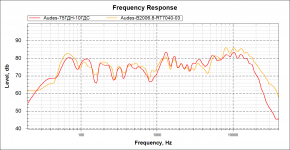
JBL 2262HPL vs 2206H vs Faital 12fh500-8 -- why the do they cost what they do?

Retail pricing:

JBL 2262HPL - $309
2206H - $450
Faital 12fh500-8 - $273

Why is JBL 2206H much more than the neo version (2262HPL) that seems to do everything better than the 2206?

I'm looking to make a 3-way with RS52AN-8 and Ribbon tweeter.
I'm already listening to this with Dayton RS270S-08 woofer and there just isn't enough woofer. I have to turn the ribbon tweeter down to max possible attenuation with the attenuator. And the mid almost to the max down level. I just don't care fore highs and mids, I guess.

I listen to speakers that are flat FR and I turn the treble way down and bass way up in my computer and then turn the bass way up on the receiver (if I have one and can) and treble way down and then it sounds normal.

I guess I'm between the Faital and 2206.
I know the 2206 has build quality that I like because I've held them, the faital looks cheaper in the pics (casting and some nuances), but I think it will sound better.

I also have a pair of ScanSpeak Revelator 22W/8857T, but they don't have the efficiency to mesh with the RS52 with no resistor on the RS52 obviously. And the ribbon would need a large resistor. Also I'm not really a fan of home style woofers in a ported box to be honest, the bass never sounds right/natural.

Faital looks like a winner, I just prefer the best possible build quality (and durability/longevity) in a woofer.
I also have a HiVi ribbon I want to try (Hi-Vi RT1C-A Isodynamic Tweeter, 120mm, 94dB).
I'm not sure if I like horns, but they don't sound offensive to me, like most dome tweeters do. I know the "standard" design with a 12 inch pro woofer is a 2-way horn (maybe with "super-tweeter) or 3-way with 6-8" pro midrange and dome tweeter.

I believe I will have a lot of room gain with the Faital woofer in the bass region BTW.

Attachments

  • Audes-75ГДН-vs-B2006.png
    Audes-75ГДН-vs-B2006.png
    43.3 KB · Views: 313
  • ZDT3.gif
    ZDT3.gif
    8.5 KB · Views: 266
  • IMG_20180220_130149.jpg
    IMG_20180220_130149.jpg
    978.5 KB · Views: 246
  • Capture-1.jpg
    Capture-1.jpg
    217.7 KB · Views: 248
  • rt1c-a.jpg
    rt1c-a.jpg
    13.8 KB · Views: 225
  • 22w_8857t.jpg
    22w_8857t.jpg
    14.2 KB · Views: 105
  • faitalpro-12FH500-size350.gif
    faitalpro-12FH500-size350.gif
    41.2 KB · Views: 119
  • jbl-2206H.gif
    jbl-2206H.gif
    17.1 KB · Views: 122
  • jbl-2262hpl-front-size301.gif
    jbl-2262hpl-front-size301.gif
    52.9 KB · Views: 139
  • jbl-2262hpl-side-size326.gif
    jbl-2262hpl-side-size326.gif
    43 KB · Views: 158

Aleph 0 layout for Aleph J

I'm contemplating building an Aleph J (or BA-3 - can't decide), and I'm looking to maximize heatsink area for a given footprint.

I'm looking at the Aleph 0 case design for inspiration (attached). Four identical heatsinks, one on each face, makes for easy construction compared to the later Aleph models with the different heatsink on the rear containing the inputs (attached). I'm considering four of the 5U/300mm Dissipante heatsinks.

However, since the inputs on the Aleph 0 are pushed to the bottom of the casing (attached), which is where the transformer is located, the input signal wiring is very close to the transformer (attached). In contrast, the traditional Dissipante layout puts the transformer relatively far away from the input wiring (attached).

Would the Aleph 0 layout result in unnecessary amounts of noise? Is the additional footprint worthwhile? I'd also have to scale back the heatsinking to the normal 4x 5U/200mm - certainly doable, but I'd like heatsink temps as low as possible.

Attachments

  • 12152611-8789-7__94310.1511218067.jpg
    12152611-8789-7__94310.1511218067.jpg
    177.6 KB · Views: 595
  • 2124.jpg
    2124.jpg
    97.1 KB · Views: 591
  • 1408578079740981946.JPG
    1408578079740981946.JPG
    186.2 KB · Views: 589
  • aleph-0-4-pass-labs.jpg
    aleph-0-4-pass-labs.jpg
    37.9 KB · Views: 596
  • IMG_9446.jpg
    IMG_9446.jpg
    368 KB · Views: 577

Audio PCB's with Sprint Layout ?

Hey guys sorry if this is not the perfect place for this post but idon't know else where?

actually you guys are making very professional PCBs designs with Sprint Layout .. Olafk and MM Alex and more... i realy need to know where is the step where you draw the schematic then transfer it to pc board to arrange the components.. OrCad and Eagle do this ... i use eagle but i think Sprint is more powerful just please guide me ??
i tried youtube and google they usefull in learning the software it self but i can't find how to draw the Schematic then transfer it to a pc board??


Thank you and sorry for long description

Want to bypass opamps in Sony Cd player

As a test DIY project, before I open up my SACD player I've opened up an old Sony 5 disc changer. I want to bypass the opamps, but I'm having a hard time determining which chip is the DAC.

I've got a CXP50116, which appears to control the display on the CD player.

I've got a CXD2500BQ, which might be a DAC, but I can't tell.

I have a CXD2560M (24pins), which I cannot find a datasheet for.

I have one final small chip which the number is rubbed off. It looks like it says "PULSE" and CXD25678 OR CX02567B or something. The number is really difficult to read so I could be way off. It's a 28 pin chip.

All of these are surface mount btw.

Any idea which of these is the DAC, and which pin I can pull L and R audio off of to wire to capacitors and then to two new chassis-mounted RCA jacks? The plan is to use a tube preamp stage between this CD player and my amp.

Thanks!

Charles.

Rohde & Schwarz UPL Floppy Access "Stack Overflow" Error

Since last summer, I have been unable to use the floppy drive on my UPL.

One day, everything was fine. The next day when I powered up the UPL, it had lost all its settings. I installed a Lithium battery on the digital board where one was indicated but not installed, and I was able to get the unit to remember settings between power ups. But from then forward, when I would access the floppy, the system would halt.

Today, I tried another floppy drive and I also tried it from within DOS.. just typing A: {ENTER} resulted in "Internal Stack Overflow - System halted" error.

I tried adding STACKS=12,256 to config.sys, but that didn't help.

Seems like I have a floppy controller problem.


UPDATE: Problem found: Floppy ribbon cable goes to DIGITAL board, not PC motherboard. That got me thinking I need to also disable floppy controller on motherboard.

That solved the conflict.

Now, I changed out the floppy drive for a Gotek USB Floppy Emulator:

Now I'm trying to make it work. I can format it in DOS, and CHKDSK thinks it's a 1.44MB disc, but but when I do a screen dump from within UPL software, it says insufficient disc space. When I read the USB on a Windows computer, it shows an empty disc.

I think one of two folks here have gotten one of these to work. If you would share what the special trick to making the UPL software play nicely with it, that would be appreciated.

EDIT 2:

Problem solved. The UPL was setup to write to a folder called \SETUPS which was missing on the newly formatted thumb drive.

Gotek USB floppy emulator installed and working!

Sound Practices CDs

Got a few mails recently from members of this forum inquiring about Sound Practices archive CDs.

I'm out of professionally reproduced CDs but would be willing to burn CD-RW copies for those who need them for $20 shipped

Paypal OK to jroberts at io.com or write for address for a check.

I am currenly in grad school studying historical archaeology and retired from the audio business. Tubes just weren't old enough for me, I guess!

Keep fighting the good fight while I'm stuck in the library!

Joe

Long tailed pair with two constant current sources

Hello everyone. I would like to know more about the transistor long tailed pair. I have seen various versions of this building block and most of them include a current mirror constant current source that replaces the emitter resistor. However, I have seen one that has two constant current sources: one in the collector and one in the emitter. Why is this useful and does it affect the quality of amplification?

Can I make use of some Electronics of old speaker system ?

Hi I have this old Philips FWD750, with three DVD , cassette players and aux input. I am just interested in using the aux input coz the whole system is ruined it works rarely, I tore it apart and found out the ADC & DAC is soldered to servo board which has a prosessor and the filters, heatsink and Amplifier is soldered to the main board. It would be perfect if i could Get it to work without removing any part just bypassing the DVD and cassete player. Incase which if its broken which is highlt priobable what parts can I salvage to hook up a aux input.

Adjustable passive radiator

Please bear with me here all. I have a pair of JBL 2269 I want to build a pair of subs with. From what I've gathered here and elsewhere is that BR and PR designs can be made to behave identically in terms of final result with a given driver, in this case the 2269.


I've discovered that shorting the driver's + and - connections with a piece of wire causes the vc to seize in the gap. This can help protect it during transport. So I'm wondering if the strength of this counter force can be varied by using a resistor instead of a wire? Further, if a variable resistor with an L-Pad were hooked up, could this then be altered 'on the fly' so to speak? If it could and a driver were substituted for a PR incorporating this system and applied to a BR box instead of a port, could the tuning be tailored for best response in a particular room with the L-Pad while listening?


If this is possible, the substitute driver/PR would not need to be an identical match to the driver making sound, and therefore cost effective, right?


Much appreciated.

Getting best audio from PC...thoughts please

Struggling to find much on this...but here goes!! 🙂


PC (MSI B360M /i5 8400 / GTX 1050ti) sends audio to AVR from Displayport, and Video by HDMI direct to TV.


Is there a better way of taking audio from the mobo (there's no s/pdif connection)??


Reason I'm looking at this is that, it seems the presence of the AVR (Anthem MRX710) seems to 'throttle' the video resolution to the TV...and this limits to 1080.


Hoped that by not taking audio from the graphics card, the screen might be 'freed up' to permit the higher resolutions it's capable of!!???


Hope that makes sense??
How about a PC soundcard with s/pdif o/p....or is that a daft way to go??

Twisted Pear Audio Buffalo-IIIse PRO ES9038

Twisted Pear Audio Buffalo-IIIse PRO ES9038

Unit works perfectly.

Build notes:
- Buffalo-IIIsePro38 2-Channel DAC w/Full Series Regulator Set
- Mercury I/V Stage
- Cronus Reclocker/Hermes/Amanero USB input
- AMB sigma11 and sigma 22 power supplies.
- Oversized, shielded transformer for analog stage
- Rear panel:
- Filtered IEC socket
- Balanced XLR and SE RCA outputs.
- USB input
- Parmetal series 20 aluminum case. 16" x 12" x 3".

- Front panel can be modified to allow for digital volume control (I will supply the relevant potentiometer), and headphone output direct from the DAC/output stage.

Asking $850 including shipping and fees.
This is slightly more than the cost for the TPA boards alone. This build cost approx. $1300

P.S life changes require full downsize of my system and projects, all of which I will be selling.

Attachments

  • 2020-04-11 18.54.01.jpg
    2020-04-11 18.54.01.jpg
    199.2 KB · Views: 552
  • 2020-04-11 18.55.20.jpg
    2020-04-11 18.55.20.jpg
    75.7 KB · Views: 534
  • 2020-04-12 00.58.17.jpg
    2020-04-12 00.58.17.jpg
    85.8 KB · Views: 564

LTspice Ncore simulation

Hello,

I haven't posted here in a while, but I do a lot of simulation with LTspice and have written a number of pages on the LTwiki including most of the Undocumented LTspice page.

Perhaps some may remember the threads on my class d Leap-Frog feedback design methods (including full LTspice models, of course). I have modeled the original UCD amplifier and run some interesting analyses of the distortion (coloration) it produces as it approaches clipping. I can't remember if I posted those models here or on the LTspice Yahoo group.

I thought it would be a fun challenge to try to model the Hypex Ncore design. My resources are the latest white paper and the USA patent. Can anyone point me to other potentially useful material? Is an Ncore schematic available? Do any simulation files already exist?

I have created a 5-pole, 4-zero (I think - haven't derived the transfer function yet) network that reproduces the magnitude loop-gain curve in the white paper. The phase response curve is not published (at least I haven't seen it), but from the simulations (both ac and transient) it is critical to always keep the zeros from drifting into the right-half plane. This is not easy to do without extreme care - kudos to Bruno.

The Ncore design is conditionally (un)stable* and can oscillate both at the intended frequency of several hundred kilohertz or at about ten times lower frequency. By shorting out the second pole pair in the feedback network one may unconditionally kick it back up to its intended operating frequency. This works well in simulation (not surprising as it is key to the operation of the real life Ncore).

The point of going all this trouble is to achieve a significant increase in (flat) loopgain across the entire audio band. When this is combined with an open-loop transfer that has been optimally linearized, the result is extremely low audio distortion without TIM or other coloration (clipping artifacts are still a weakness, at least in the simulation).

Before I upload a simulation file that is off the mark, I was hoping to collect any further detailed information available.

By the way, I hadn't really looked into the Ncore before now - Bruno is a genius.
___________________

* Not sure of the correct terminology for the fascinating feedback topology of the Ncore.

Best amplification solution for Roland TD-50 Drums

Hi all,

I'm new to this forum, and very novice on this topic in general so I appreciate any advice you can give in advance (and apologize for any missing details or misunderstandings in my post).

In short: I have a Roland V-drums (TD-50) kit that I use for practice in my house, and currently play almost exclusively though headphones. Recently, I've been considering playing out a bit (bar/restaurant type situations, so relatively small rooms). I'm trying to figure out how is best to amplify my kit so I can achieve overall good quality drum sound (doesn't have to be pro level quality though) and I'm specifically interested in making sure the thump of the kick drum and floor toms come though in the sound (not playing heavy rock/metal so I don't need the kick to be eardrum shattering), just a nice round thump.

I currently have a small EON206P Personal PA system system that I've used for playing music at small house parties, that I'm kind of hoping I may be able to utilize to some extent. However, the EON206Ps really lack any low end, and the kick sounds terrible though just those speakers.

I'm considering 2 options (although open to any suggestions):
1) Buy a powered subwoofer that I can run off a separate out from the TD-50 module to round out the low end, and rely on my current JBL EPON2016 to provide the mid-highs.
2) Buy a slightly more all-purpose speaker that will add more low end, but also provide some support in the mid-range and overall amplification.

I'm trying to keep the budget under a max of $700 max for the final solution.

For Option 1 I've come across a few different subwoofers online:
1.)Mackie Thump 18S - $699 US
2.) Harbinger VARI V2318S 18" 2,400W Powered Subwoofer - $599 US
3.) JBL EON618S - $699 US

For Option 2 the options I'm considering are:
1.) Mackie Thump 15A 15 in. Powered Loudspeaker - $349 US
2.) JBL EON615 - $399 US

My main questions for anyone who is willing to give their input on this are:
1) Does the Option 1 solution with a subwoofer paired with my current EPON2016 personal make sense or does this seem weird to add a powerful subwoofer to a very underpowered personal PA system? Again, I only need enough sound for a small room with 20-30 people, but want to make sure I can get a little tump from the kick drum.

2.) In Option 2, do others think that the 15" powered speaker options that I linked to would have enough low end to provide the desired kick drum thump?

3.) Are there other speaker options/combinations that I haven't mentioned that would achieve the desires result in the same basic price range? I do want to stick to relatively reputable & quality manufacturers (not looking for total low-end band/quality just to keep the price down).

Thank you very much for any input you can provide and please let know if there are any other details or missing info I can fill in!

Cheers,
Nick

converting channel fader to rotary pot

Have a Allen and Heath Xone 02 dj mixer. It's a 2 channel mixer, each channel stereo. I want to add pots to it to control each channels volume. I took it apart, The channel faders sit on a pcb, with 4 pin connector on it. What I don't fully understand is how the channel fader works with 4 wires, instead of the normal 6 wires that are standard on like a ALPS RK27. Can anyone help me make sense of that?

:cop:

Mod note: Please upload images directly using the advanced editor instead of hotlinking to other sites, thanks!

:cop:

TL with Dayton DMA58-4

Seems like these tiny drivers might be fun, at least down to 150hz where 2mm xmax is exceeded. The xmech seems to be just over 4mm, so maybe even useful to 60hz with more distortion?
Am I mistaken and missing something? This is vastly better than sealed or ported sims out to?

Attachments

  • Screen Shot 2020-04-24 at 6.03.20 PM.png
    Screen Shot 2020-04-24 at 6.03.20 PM.png
    126.2 KB · Views: 106
  • Screen Shot 2020-04-24 at 6.03.05 PM.png
    Screen Shot 2020-04-24 at 6.03.05 PM.png
    228 KB · Views: 95

I have a chance to buy B&G RD-75's's

Hello, I have found someone with some original "NOS", Bohlender Graebener RG-75's OR RD-75's OR 1.9's. does anyone know the differences in these models? I am wondering which is better for a home line source. And overall what the difference were. I was reading recently about a fellow whom built a line source back when the RG-75 was first manufactured. He raved about it. But I am taking that with a grain of salt. I do know I would like to try it but I do not know much about them. Other than 6'-3" tall and can be run from 150Hz - 40KHz. At least that's what I have read. I cannot find too much on-line about them. I'm wondering if this is a deal or a bust. ANY help/info would be highly appreciated.

I am currently working on developing a line source speaker using the B&G Neo 3, Neo8 and Neo10 so I have a little experience with them but the RG-75 sound like the "pinnacle", of what B&G's, R&D came up with and actually manufactured. Even though only for a limited time.

s-l1600.jpg

FS: Valvo ECL86

I guess like most people atm, I am cleaning up the office/workshop
1 x Original Valvo ECL86

Pulled from a Grundig 3010H which was in absolute MINT condition.
The radio is not for sale (or do me a REALLY good offer)

The tube is tested and measures still really really fine.

Price: 25 euro excl shipping

I am based in Europe

Attachments

  • ECL86_valvo.jpg
    ECL86_valvo.jpg
    411.9 KB · Views: 122
  • 1.JPG
    1.JPG
    171.1 KB · Views: 121

F5 bias and thermal issues

hi - i am about to finish my F5 build but obviously i did it first without thinking! My layout is as below. I think i am going to have two issues 1) bias - but i thought i could get away it it by biasing the amp as shown and then put it back together after. I know that you suppose to wait for 2 hours with the lid closed so this could be a problem

2) the f5 board may not have enough ventilation because it is mounted vertically near the transformer at the back. Is this going to be a problem? I don't know if it makes any difference mounting it this way

at the end of the day, if i have to redrill and tap again then i will do it. i could put the PSU in front of the transformer and use two monolithic diodes instead to save space (I have the KBPC3510). Is this ok?

I heard that it gets very hot and the JFETs will blow so i don't want this to happen.

Thank you very much for any help

Philip

Attachments

  • IMG_1838.jpg
    IMG_1838.jpg
    558.3 KB · Views: 268

Interest for potential GB for UDNess PCBs and matched FETs.

This is my first attempt to organize a group buy. I'm offering a lot of transparency re: how I think this could work (or not), so if there are constructive thoughts to make it a better experience, please share.

See Original Thread

UDNeSS, or You don't need Semisouth's

This thread is to gauge interest. I'll also hear any advice or requirements for matching parts. I've offered my thoughts, but I'm pretty flexible. I'm also very new to DIY and electronics in general, so I may be wrong 😱 in some cases.

I would be willing to buy and distribute (in the lower 48 only) a set comprised of -

2 - main board PCBs - using Patrick's Gerbers
2 - supplemental boards allowing use of 2SK209s for Q2, Q3 - using Patrick's Gerbers
4 - (2 matched pairs) Fairchild Mosfets FQA9P25
8 - (2 matched quads) 2SK209BL
2 - J113 with min 8.5 Idss

I'd be willing to match / sort parts for up to 10 sets / 20 channels. I'd be willing to order parts and distribute up to 20 total shipments. If in addition some people wanted boards, but no parts or boards and a pile of FETs to match themselves. Fine by me. I'd base it off interest. To keep it fair, I'd initially limit it to one set of boards and/or parts per person. I'm not going to donate my labor to one person that wants 20 channels. They can sort their own parts. :rofl:

re: MOSFETs matching.

I researched across the forum. There seems to be a lot of discussion around the process to match these parts and parts like them. I would match the Fairchild parts @22V0 / 1A4. Matches within 5% should be achievable with a decent yield. I usually match parts like this without a heatsink after 30s. I'd be willing to use a heatsink jig with clips and take the measurement at 1min. If it's simple and improves reliability / confidence, I'll do it.

If a heatsink is used I will start all parts at roughly the same room temp and take the measurement within a second or two of a given time after the voltage is applied.

I will not:
bolt each part at a standard torque using a specified washer area to deliver the precise thermal coupling;
keep a heatsink at a known temperature;
allow the heatsink to cool between measurements;
use anyone's favorite thermal compound;
use new thermal compound between measurements;
or guarantee timing to the ms.

I'm not willing to go to that level of effort.

In a different field, I've done extensive work determining the precision and accuracy for standardized test methodologies and instrumentation. I've also determined the expected variation within, between, and overall among operators trained in standard methods using standardized samples with standard / calibrated instruments. From what I've seen in the threads - even if I tried to improve the accuracy of the measurement by using heatsinks, it probably would not result in a more precise/reliable match. We're looking for matches, not the absolute value or accuracy of the measurement at operating conditions. We're assuming that if parts match under certain reasonable conditions when measured a certain way - that they will also match under the actual operating conditions closely enough. I actually find it interesting when people record the values to 4 significant digits. My guess based on matching about 100 similar devices, is that the measurement error alone may allow a precision closer to 2. If that's a dealbreaker for some people, no worries. I'm willing to do the work within reason. I also love to learn. So, if there's a measurement method that can be accomplished in <5 mins per part that results in more reliable matching - send it my way with your thoughts as to why it would ensure a better match. I'm not interested in theory re: why it would provide a more accurate absolute result. I understand that already.

I appreciate Patrick's policy of not providing matching data. I will follow suit. My commitment will be to match the parts to an agreed process. Providing values for each part will only serve to cause confusion. IMO, there is just too much potential variability in the measurement methodologies to provide an absolute measurement. If I write down 4 values of 4.44, 4.44, 4.45 and 4.46 - then someone measures them at home and finds... 4.31, 4.32, 4.35, 4.38. I'm not willing to deal with the potential outcry.​

re: 2SK209s

I would match using this jig recommended by Patrick
Peak SOT23 Adapter for Testing Parts on DCA55 DCA75 Model PCA23 Atlas | eBay

It looks nifty. I'll buy it and not pass that cost along. I know I'd use it for other projects. I have a pile of BF862, and I'd have loved to have this jig when matching those! I'd also consider providing 2 matched pents. They're small. There's a reasonable likelihood that someone is going to drop one... damage one etc. There's no way I could send out a replacement part with a known value. OK. I could, but I'd charge A LOT for that. If I get enough parts, and the values match tightly enough, I'd just send along pents vs. quads.

re: J113s
I'd sort all J113s >8.5mA IDSS, then pair them off by the closest values.

Goals
My goal is to build a couple working channels for myself, give a bit of my time back to the community that's been so generous to me, and maybe save a few of you a buck or two and a lot of time.

The first question I anticipate is cost. I have no idea. I've never ordered PCBs. I'd calc the costs as such:

  • PCB cost goes to each person. I'd likely round it to some clean value erring on the side of value for the buyer.
  • Total cost of all the parts gets divided among people that want them. I've been told to expect ~20-30% yield. I'd order about 5x the number of parts on the conservative side. Given the cost discounts at volumes, I think it's still cheaper than buying just the number of parts required. Again, I'd likely round to a simple number erring on the value going to the buyer.
  • I'd ballpark shipping and packaging (based on similar GBs I've participated in) at about $7 per order. I will charge a flat rate just to make it easier for me to collect payments. Don't gripe if your actual shipping + envelope is <$7, and be thankful if yours is > $7.
  • My labor and other parts / jigs I'd buy or build - no cost passed on.
  • The experience of building this fantastic design at such a low cost - priceless 😀

I had posted in the other thread that I'd send out all remaining unmatched parts to the group. I was told that was not wise. So, I will follow the advice and not send out unmatched / unused parts. However, like with the 2SK209s if I have enough matches to provide an extra or two, then don't be surprised to find a lagniappe in your goody bag.

Thoughts? Interest?

:cheers: to Patrick (@EUVL), @Morde, and a fantastic DIY community
JL Audio 900/5

Hi guys,

this amps doesn't turn on but the power supply is ok because all voltages are present and correct (+15, -15, +5, -5 +35 and -35) with an idle current about 2,5 A.

I think there is a missing connection because the "big hole" at center of the mother board. Problem is i dont't have any schematics of information about mother board traces

But this amp have a "three slice" board ? Because surface is connect to ground, just a little bit inside the board (if i put a tester plug inside the hole) there is a +12 V ....

Thanks for your help.

Giovanni

Attachments

  • IMG_20200423_180010.jpg
    IMG_20200423_180010.jpg
    851.8 KB · Views: 105

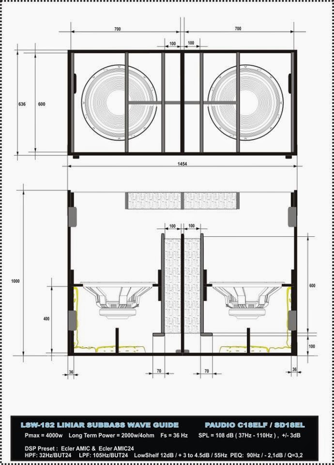
Dynacord LSW

Hello people. i want to decide what pair of subwoofers i should build (teknival and edm ussage). I saw a plan from dynacord and seems preety simple to make. My question is: Did somebody hear or saw a builded one? I couldn't find anything on internet exept the plan. Or, how this planar will sound in comparation with a th18, bph or a scoop (my other choices for the build) The drivers will be 18tbx100 or void v18
I have a small dual 15 planar box but i can't hear a big difference than a br box, maybe a lil bit in directivity. Goal is @40 hz flat; or less.

I'm really into this project for the simplicity and the size of it (i can easely put a fullrange on top and will be at head level)
998256_494937583911720_1365378691_n.jpg
Projects by fanatics, for fanatics
Get answers and advice for everyone wanting to learn the art of audio.
Join the Community
508,468
Members
7,920,950
Messages

Filter

Forum Statistics

Threads
407,832
Messages
7,920,950
Members
508,468
Latest member
Wheelman