choke input PS throws noise like crazy

Simply to hit a voltage with a transformer I could find in my junk bin I built a choke input power supply for the first time. Silicon full wave rectifier (each diode capacitor bypassed), 280 V AC to 250V DC, 50 ma. Big-a55 150ma 10Hy choke (garage sale prize) for the input, then 220 uF cap and a smaller choke to supply the output stage for a 3w SE amp, still kind of slop-built on my bench. So far so good.

After putting it into use the buzz and hum in the amp was very noticeably worse. Dinking around a bit I found that just touching the big choke, or moving tools or my hand around it, hugely affected the hum. Wrapping it with a couple layers of grounded copper foil and sticking a grounded piece of steel sheet between it and the amp minimized the problem, but it's still there

Is this just inevitable with choke input power supplies, or is there a smarter way to put them together? Right now putting the power supply at a distance from the amp is as good an idea as I have.

Dirty USB ?

I am attempting to create a digital playback device (i believe they are called 'renderers' now) to feed hi res audio to a dac. I would build this device based on either PC or Pi hardware.

As these do not tend to have spdif outputs, I am relegated to using USB or optical. I read that USB is the 'best' choice.


I also read that the clocking on onboard USB is bad and I either need a precision clocked USB card or an external 'reclocker' ( I fail to see how this could work. But I'm stupid). Incidentally, a 'recommended' add on board manufacturer claims the crystals supplied with his board are just for 'proof of concept', and for best results I should replace them with better ones. Eh ?


What would be the best solution here without breaking the bank ? The external dac I have is quite good. Or supposed to be.


Thanks,


Pete

Michaelson and Austin TVA-1

I am the owner of a TVA-1 , one of the erly amplifier types from Michaelson and Austin with the small powertransformer, and I need a picture of the original ground wiring.

The amplifier was received with some soldering changes made for the ground connection. Its difficult to keep the weak 50-60 Hz hum away from the speakers.

A hole has been drilled in the midle of the TVA-1 for gnd., but the central ground point should be close to the large psu capacitors under the psu-PCB? ...or?

thanks

upgrade opt or no?

Is it worth 'upgrading' the output transformers on this KT88 SE UL amp:
KT88, (ect) Single ended amp, SEUL | Audiokarma Home Audio Stereo Discussion Forums
or would it be strongly into the region of very diminishing returns and I should save the money for a new build at a later date?

Currently I'm running edcor CXSE25-5K.

If it is worth it what would you suggest?

I've got Electraprint iron in my PP 6V6 amp and like it but have also looked at the ISO FC-20S. I've also looked at toroidy but not sure if that is an upgrade or just something different and it wouldn't fit on the current chassis.

DG 300B Amp

Sold! DG 300B Amp

Sold!

For sale all boards needed to build Neurochromes DG 300B amp.
Includes 21st Century Madera High Voltage Regulator
Filament supply boards for 5V (2 boards) and 6.3V (1 board)
Power supply board
Amp board. Board has been attached to a plate (with screws) machined by Front Panel Design.
All the power supply/regulator boards have been tested. Amp board has not.
As shown, all boards have been populated.

$125.00 includes shipping (US only). Also, only PayPal gift.

Attachments

  • IMG_0383.JPG
    IMG_0383.JPG
    165.7 KB · Views: 357

For sale or trade Completely Working F4 Boards

I helped a friend change his F4 to an F5 and I have these completely working F4 boards for sale or trade. I already have 2 F4's and do not want to build another one. The boards have Linear System Jfets.

I am either looking to trade or sell the boards for any of the options below:

- $150 cash plus Ship

I prefer to ship only to CONUS.

Attachments

  • IMG_0375.jpg
    IMG_0375.jpg
    484.1 KB · Views: 462

Is this a novel OS topology?

novel_OS.png


A voltage input is converted to current by R10, fed to the resistors R8 and R7 which convert back to voltage to drive the lateral MOSFET gates. The inner quad Q1/2/3/4 is like a translinear loop and serves to set the bias as well as cancel the Vbe drops of Q3/Q1 on the signal path.

Some local feedback via R11 serves to increase linearity somewhat, but the driver stage can be opamp-based as the signal swing needed into R10 is about 10V and 20mA peak.

The current-mirror style cascode transistors Q5/Q6 serve to keep the dissipation in Q/1/2/3/4 all low to reduce self-heating.effects.

I haven't investigated real-world thermal stability of the configuration yet, but it should be possible to do that at low voltage without output devices since R7 and R8 are current driven, which is rather convenient - next step is choosing a breadboard to stripdown and reuse, mine are all full ATM!

My first amplifier - Need help

Tpa3255 or Irs2092 - My first amplifier

Hi all,

It's one of my first posts here but I spend a lot of time to read your valuable forum. I am a beginner in electronic so please don't be too much rude with me... ;-)

I want build my first amplifier during this period of quarantine, to try to learn something and spend my time a little bit better.

I have a lot of concern about it, but the first, is which type of board I have to pick. The 2 main options are tpa3255 or Irs2092.

The tpa3255 seems that the best one is the one provided by 3e audio.

For Irs2092 I have some options. The first 2, is an already build and tested boards:

Sure Electronics 2x125w

WONDOM | STORE


LJM L15D-power (It is good because have integrated already speaker protection and rectifier.

LJM de Audio ensamblados L15D POWER IRS2092 300W Mono placa amplificadora de potencia con proteccion de energia HiFi Digital AMPLIFICADOR DE POTENCIA DE Audio|power amplifier board|amplifier boardmono power amplifier board - AliExpress


The second option (and it is my preferred) is buy a DIY kit, to build manually my amp with the solder.

LJM L15D-PRO is the only available kit that I found, and I don't know if it is LJM original one, with a good set components (And the rectify part is missing, only the speaker protection circuit is available)

Nuevo Dual canal L15D PRO Clase D IRS2092 IRFB4019 AMPLIFICADOR DE POTENCIA ESTEREO DIY Kit (, 2) 300W|amplifier diy|amplifier classpower amplifier - AliExpress


In theory my target is build an integrated amplifier with a preamp and a DAC included.
My objective is that the quality of sound must be best of possible (HIFI?) and have a really quite output in idle without hiss, pop, or ommm noises. (I own a DENON 3500, and could be nice if my selfmade amp could be better that this)

The preamplifier that I have in mind to build and use with the above boards is this one:

Mezmerize B1 Buffer – diyAudio Store

What do you think about it?

Could you help me? (@ljm_ljm)

Thank you a lot.

Hello from minnesota

I am new to all posting of any kind. This site is my first, but could not resist.
Please forgive any clumbsyness in my posting process.

I am a EE nearing retirement, and beginning to have time to contribute and learn about audio.

My background is in low power a analog IC design for medical devices. I also have some experience in high voltage a d power conversion.

What should I do with my Arctics?

Hello everyone, it has been awhile since I have posted here. I have two pair of Pinnacle Arctic 1's and a pair of Pinnacle Arctic 2's.

Arctic 1

IMG_2765.jpg


Arctic 2

IMG_2764.jpg


I also have enough extra woofers and tweeters to make an extra MTM Arctic 2 giving me enough to make a 7.1 channel home theater. I cannot find anything about these on the web at all. I called Pinnacle and talked to a tech who has been there quite awhile that gave me a little info. The Arctics were built in 1993 and were considered a premier speaker but were short lived due to the fact that the cabinets cost too much to manufacture. They were hand painted and had too many hours into them. They do have a beautiful gloss finish. The 1's were $375 and 2's were $475 I believe. They use 1 inch aluminum dome tweeters and 5-1/4" poly cone mids, both made by peerless

IMG_2768.jpg


IMG_2772.jpg


IMG_2775.jpg


IMG_2774.jpg


IMG_2776.jpg


These have to be one of the cleanest, best sounding speakers I have heard. They do everything very well with the exception of bass, but I believe almost all bookshelves need subwoofers. I have heard many speakers and these have always trumped when it comes to treble, midrange, midbass, especially vocals and strings.

My father and I were talking and thought it would be fun to do a tower, a small line array, possibly open baffle. Problem is I don't know the T/S parameters. The crossovers for the Arctic 1's seem simple using electrolytic caps, here is a schematic. (my first time drawing one so please point out anything that looks wrong)

scan0003.jpg


So what would you do?

1. Build the extra MTM for home theater and leave it alone

2. Build the MTM and replace all of the caps with better ones (about $50 a pair for crosscaps)

3. Build a pair of towers using four woofers per side

4. Find two more woofers and build small line arrays (maybe open baffle)

hmmm.

Also, if I were to send someone trustworthy a woofer would they be able to measure it for me so that I can find out the best app for it?

Thanks for your time,
Dan

Tapped horn, 3d model / automatic folding

I have made a 3d model of a tapped horn / tapped pipe where the different variables for throat / mouth and length can be changed and it will redraw itself to the new parameters automatically. This is a part of a set of subs that I plan to build, but I think that the idea of it, the 3d model that you can plug numbers into is a good idea for the community to have, and would like to have some people try it out to see if it's something worth doing more of.

Link to model

0B6F18F7-F582-4977-A8DB-ED4600D18586_zpsjsjqthpy.png


DISCLAIMERS: (please read)

The model is made in Onshape. You need to signup for a free account to edit the model, but there is not software to install it's all in browser, unless you plan to use a mobile device. Then there are apps for that (mobile is a better UX actually, I used my phone to make the model.)

The length variable is NOT accurate, however if you view "Sketch2" there is a dashed line running down the center of the horn, select all of it's segments then tap the calipers icon on the top and it will give you a very close approximation of the actual length, then you can adjust the variable up or down and remeasure. I'm not sure how to fix that. I tried using a correction algorithm that got it closer, but it still wasn't right.

15C0E714-800B-4BCB-BD69-77890387E433_zpsfzsqq5kp.png


If you select part4 and press the scales icon it will tell you the total volume of the horn.

A37134EF-7AA2-49F5-97ED-4635B66BED16_zpsumnvvobw.png


If you select all of the parts (except part4) it will give you an estimated weight (for plywood and polycarbonate and an as of now imaginary driver)

E0C2B3CD-57D0-4689-87AD-5CA79B6EC2B1_zps6i9s75dd.png


The model is meant for stacked cnc cut plywood with polycarbonate sides, if enough people think it's a useful idea then I will make a few for more affordable, less wasteful construction, and more flexible fold styles.

it's constant flare only, I haven't tried compound flares yet, not sure how that would behave.

If you go too high or low with the variables the model will twist itself into a knot, just hit undo and it will go back together. This isn't the most flexible folding style, but it looks really nice with clear sides and it keeps the mouth on the floor.

The driver in the model is one I'm designing custom for this sub, it's not done, and is just there to give a size reference.

Power supply for a tube DAC

Hello guys. I have built a dc coupled two stage DAC output like from the schematic. In the original version I had 10H 120ohm choke, and the last two capacitors were 330uf electrolytics and resistors 470 ohm.
It played really well, but I thought I can make an improvement.

I was suggested by a friend to replace the last elcos with 20uF foils.
I also replaced 470ohms for 1k2 for better filtraton and time constant with the smaller capacitors.
I fired it up and.... everything cleared up a bit, highs were better, the usual improvement when you replace electrolytic with foil. But the energetic deep bass that I was proud of are not here so good.
I thought why?
First reason will be that the B+ voltage for 6N2P will be slightly lower, but I dont trust that 1 volt difference can be so big in sound.
Than I replaced the chokes. (every time I added bigger choke to a power supply, sound was again more dynamic and energetic). This didnt improve the energy.
The other reason can be simple:
simply that the new caps can not store so much energy as the big elcos....
But Im still confused.
In my power amp, I have driver stage which draws 5mA. And totally doesnt matter if the filtration paper in oil here is 5uF or 10uF or 15uF. Even if I increase the dropping resistor a bit, no difference in sound.


I simply dont trust that Ive moved the operating point too far from the original, by having a 5 volt loss for the 6N6Ps and 1 volt difference on 6N2P. Or do you think it can be the case?

They are schematics.

An externally hosted image should be here but it was not working when we last tested it.


An externally hosted image should be here but it was not working when we last tested it.


Thank you very much for help. Best regards, Michal

For Sale F5t part built boards (used)

My ongoing clear out of amplifiers:- I have a set of these F5t boards which as you can see I have cannibalised for other later projects. The Mosfets and jfets removed, everything else is in place as was when last used working perfectly...All the resistors are dale even the 5 watt and the caps are Muse Gold.

49865394628_eca1911a41_k_d.jpg


49865394498_3cf8359d29_k_d.jpg


I have a set of matched quad jfets 170/74 GR's which where used in this amp before I went to quads in both for 100watts per channel.

They all measure good and OK.

49865394323_b6e5595eca_k_d.jpg


49865394218_1c814a941f_k_d.jpg


£100 the lot + P&P at cost

PM please

OTK 6J1 biasing problems

Hi folks,

This is Vincent from Hong Kong and it is my first post in DIY Audio. Nice meeting you guys here.

Recently I'm working on adjusting OTK 6J1 biasing voltage. The 6J1 is triode connected and self-biased. I found that the cathode voltage is not stable with certain combination of anode resistors and cathode resistors. By "unstable" I meant the voltage is varying up and down.

In addition, as the 6J1 is triode connected, the anode current should be the same as cathode current, right? However if Ia-Ik, the result is not always zero. What did I do wrong? Please see the schematic and data below. Thanks guys!

Attachments

  • data.jpg
    data.jpg
    104.4 KB · Views: 160
  • 6J1.jpg
    6J1.jpg
    274.4 KB · Views: 165
  • 6J1 Bias.jpg
    6J1 Bias.jpg
    74.8 KB · Views: 174

cdm4 mechanical problem - disc rubs, not spinning freely

cdm4 mechanical problem - disc rubs, not spinning freely (solved, mods report)

Hi,
I did a thorough search on diyaudio but couldn't find anything concrete, so I'm asking for a little help or suggestions:

Just got a well looking Grundig CD3000 (cdm4 with tda1543, planning some nice mods here when I get it working), which doesn't read discs for a low price. Tested it and turns out that the laser appears to be fine, fortunately, but it rather seems to have a mechanical problem: the disc starts to spin but seems to rub against the base of the transport or the platter, I'm not sure, so it gives up with ERR. I decided to test further by inserting a piece of paper underneath the cd onto the disc platter - now, disc would rub less and start to spin up to right speed, making less rubbing noise, but still not reading. I figured the focus distance would not be perfect due to the paper, so I slightly pressed on top of the clamp and now the player was able to read TOC and started to read a track with heavy skipping. Still some rubbing sound, which would explain the skipping.

So, does anyone have an idea what might be the problem? If it was a CDM1 I'd say that the disc platter had lowered on the shaft due to wear, but I don't think this can happen to cdm4, also the paper test seems to prove the opposite, as it only starts reading when pressed down (so it can't be lower than original, as I haven't touched any trimpots).

Could it be damaged or worn clamp? I've heard about some bearing but I can't seem to find it. Could the transport base not get low enough when loading the disc and be rubbing against the cd? a very well working tray loading mechanism (often these infamous gear breaks) speaks against this, but I don't know.

I have two other working cdm4 based players here, so I might start to compare them bit by bit to the defective cdm4 and try to find out what's going on, but I though maybe this is a common problem and someone could give me some hints, sparing me some time.
Thanks in advance.

P.S.: I've repaired a couple of CDM2 transports so I've got general knowledge about repairing philips swing arm mechanism, but didn't repair any cdm4 yet.

Could someone check my circuit?

Could someone look at my circuit if there is something not right about it?
It's a stereo preamp (one channel shown) which also serves as a low gain mic preamp. I've build it years ego but did some minor changes and also changed the output from anode to cathode so I can connect it to heavier loads like solid state mixer without worrying about over loading the output. Thanks for any info.
Also, I thought about implementing NFB but didn't bother because it would lower the all ready fairly low gain for mic, but would it be worth the trouble anyway?


An externally hosted image should be here but it was not working when we last tested it.

Attachments

  • preamp-2.jpg
    preamp-2.jpg
    58 KB · Views: 243

Crazy CD player problem - completely muted

I have just received my Audio Aero Capitole mk2 after a Signature Edition upgrade and a transport change by Audio Aero factory in france. The player is 7 yrs old, but never had any major problems.

It now has a big problem which I am unable to solve. It remains muted. On very rare occasion, the sound comes back after re-powering up and once it starts play, it continues to play flawlessly for weeks until I stop it. The moment it is stopped, it mutes itself and is extremely difficult to get it to play again.

I disassembled the transport, reseated all the internal cables, changed /tried different software chips, but everything works fine except the muting problem. Currently it has a 5.6 chip.

The disc spins, the player recognises the cd tracks, displays the track and time (of the playing disc), volume control works, etc.. but no sound.

When fed with an external transport through a digital input, the muting problem very much remains.

I just can't get it to play!! Checked the Integrated circuits, they all seem fine: no cracks at all etc. The two output miniature tubes glow and power is passing through nicely.

I am presently in a dispute with Audio Aero over this very problem and the player is not going back to the factory. Where I live, there is no Audio Aero dealers, but I do have a qualified electronics engineer/technician who services pioneer and technics CD players.

My amp works fine with a different source. My interconnects are not faulty.

Would really appreciate any idea on what could be wrong and how to go about getting it to play. It's crazy.
Many thanks.
lall

Simulating a sound diffuser

Pascal Pharmacon posted an interesting article yesterday, so I thought I'd find out how they perform:

https://phys.org/news/2017-06-diffuser-ten-thinner.html

From what I can tell, this is a conventional quadratic diffuser, but the "wells" in the diffuser have been squashed so that the sound radiates radially.

So let's find out!

zIwcj3y.gif


First off, here's a sim of how sound radiates in a room. The dimensions of the sim are 200cm x 200cm (6.5' x 6.5')

The speaker on the left is 20cm in diameter (8")

The frequency is 1000Hz

Is fullrange (horn) the right for me?

I am looking in to building new floor speakers, currently I have three way conventional bass reflex with bi-amping and active crossover.

They will be used for both TV/movie and music (no disco or metal, mostly jazz and folk). No subwoofer will be used.

How would fullrange 8" satisfy this? Seas FA22RCZ in a vented (sealable) enclosure, (in Finnish) Audiokit Aw-F22 rakennussarja - Hifitalo ?

Or the same driver in a horn enclosure, Mauhorn IV – D a r k L a n t e r n ? How do they sound, are they very directional and difficult to place in an apartment?

I have access to a full fledged carpentry workshop but no competence in designing enclosures.

FS: Twisted Pear Buffalo Set with Beaglebone

Too many DAC's therefore selling this setup, inlcuded is :

- Beaglebone Black with working Botic image
- Placid Supply
- Hermes
- Cronus
- Buffalo IIISE including Crystek Clocks and local Powersuppy Regs
- Legato I/V output stage

all of course in fully working condition ...

Asking 450,- Euro for the setup + shipping which of course depends on the destination

thx

Attachments

  • dac.jpg
    dac.jpg
    600.8 KB · Views: 291

Sure / Wondom amp gain setting adjustment - how?

I have a Sure/Wondom AA-AB35281 amplifier board.

The specs PDF states:
"Gain: Min 28.5, Typical 30.5, Max 32.5"

This leads be to believe the gain setting is adjustable.
But the PDF doesn't state whether it can be adjusted or how if so.
Does anyone know if it can be adjusted and if so, how?

PE Specs sheet:
https://www.parts-express.com/pedoc...200w-fanless-audio-amplifier-board-manual.pdf

Eclipse XA1200 ICE

Hi everyone¡¡

Today comes to me an eclipse xa1200 ice amp.

I dont test any amp, before i check the inside. In this one i find a rarely and 100% sure bad conection on the irf1010 ps mosfet, see the image.

So i take off all the ps mosfets and test it. No power, no 12v on the tl494 so replace the remote signal transistor. 12v on vcc and c1 and c2 of the tl. Now i have around 4-5v on the tl outputs, but im sure the ps mosfets drivers are grone. Anyone here have the shematic or the corrct part nunber for q919 and q921?

Thanks!

Attachments

  • 20200305_210919.jpg
    20200305_210919.jpg
    239.7 KB · Views: 144
  • 20200305_210852.jpg
    20200305_210852.jpg
    432.3 KB · Views: 145

Edge diffraction check

Hi
I intend to put a 12” AE Dipole woofer on an OB which will be about 56cm wide by say 50 cm tall. I will also put some short wings on the baffle. I will run the woofer up to 600hz. I have read what Linkwitz has to say about diffraction and I want to just check I’ve understood correctly. The wavelength at 600hz is 57cm, so I’ve concluded that edge diffraction should not be an issue. Have I got that right?

Massive mono battery supplies

Hi All,

I have inherited two massive LIFE PO4 batteries in nice alloy cases (30Kg each and approx £1,100 RRP each!) they are 48 volt / 150 Amp Hours rated and would like to use them as the power supplies and physical bases for a pair of floor standing active monitors.

Each 3 way monitor stack has three separate monoblock 500 watt class D amps and 3 channels of DAC per speaker, so 6 channels amps and dacs in total.
The 6 Ohm bass section is 95dB per watt @ 1 meter.
The 8 Ohm mids are 100dB and the TPL tweeter is 100dB sensitivity.
DAC's and A to D are built into the amps and the only input is an optical Toslink (no electrical connection with the music server / DSP)

I want to run the whole system from the batteries and use DC to DC voltage/current reduction for the amplifier boards and DAC's.

Questions:
What is the best approach or technique to achieve DC to DC reduction in this situation and any company or product component recommendations would be much appreciated!
Highest audio quality is my goal and I don't want to waste these super expensive batteries by scrimping on the DC reduction.
Thanks in advance
Alex.

Skar RP 2000.1D In Protect

Hi fellow social distancers, Got two Skar RP 2000.1D in for repair. Both in protect. Power supply runs. No shorted outputs. Pulled all the outputs to see if it made a difference. No change. The protect circuit is controlled by a 393 comparator chip. Just to be sure I changed the 393 chip. No change. Can anyone shed some light on the protect circuit in these amps? Thanks


LM393

Pin 1: +5.2V
Pin 2: +5V
Pin 3: +8.5V
Pin 4: Gnd
Pin 5: +2.5V
Pin 6: +2.2V
Pin 7: +5.2V
Pin 8: +14V

Panel switch/lamp/fuse combination

This would solve my diy AC line connection nicely using one panel hole.
Ya not for the EU probably but North America we still using line cords.
I have one of the surplus experts looking for a NOS stock.
The IEC panel entry is a pain if fabricating enclosures, and the switch/lamp/fuse system is fragile.

Attachments

Free (Australia): TDA1543, TDA1545, K170

During my clean out I found these which may be of some use to someone. I'll give it a week before I throw them out. I'll cover postage and ship in Australia only.

TDA1543 DAC new
TDA1543A DAC used in a NOS DAC
TDA1545A DAC new
4 x K170 used (was in a B1 buffer) and were originally matched but can't say they are now

Attachments

  • RZ_DAC_TDA.jpg
    RZ_DAC_TDA.jpg
    118.4 KB · Views: 256
  • RZ_K170.jpg
    RZ_K170.jpg
    94.9 KB · Views: 252

Passive radiators

Hi all
I have a pair of 5-1/4" KEF passive radiators to sell. They were from some KEF Cantor 111 Speakers whose woofers died by teenage hands. The outer frame dimensions are 8-1/4" x 8-1/4".

They are in very nice condition - no sign of surround deterioration.
$40.00 for the pair. Buyer pays shipping. Shipping weight 275 grm each plus packaging.
Regards John L.

Speaker Build Idea - F'AST Build

Does this speaker build idea using these two drivers in a ported cabinet ala cheap DeVore Orangatun O/96 style, a bad idea?

Dayton Audio PA310-8 12" Pro Woofer

Peerless by Tymphany BC25SC08-08 1" Fabric Dome Tweeter 8 Ohm

If I could get 45hz out of it, I would be happy, yet if I could get 40hz even happier.

Looking for a high efficiency build for my Sony V-Fet and Music Reference RM-10.

Thanks

LMC7660 based DAC power supply

Hello! I have a Musical Fidelity V2 DAC and trying to understand the power supply plan.
It uses unipolar power supply 12V and for the opamps creates the negative rail using two DCDC charge pumps LMC7660 from TI.

When measuring the two rails that feeds opmaps i measure a difference of minimum 1.5V and i want to try and correct this issue if possible.
As can be seen on the picture the positve rail goes almost unchanged from power supply to opamps.
The input on pin 8 of charge pumps is 8,9V and on pin 5 I measure 7,8V. I was expecting to have Vout equal -Vinput.
The group formed by C21,C44, D3, D4 also confuses me because in the end I have -12,6V on opamp negative rail.
What is the role of C21,C44, D3, D4?
What can I do to have equal voltages on opamps rails?
I attached the complete schematic of DAc and also a screenshot with measured voltages.
Thanks! Adrian

Attachments

  • vdac complete schematic.jpg
    vdac complete schematic.jpg
    218.2 KB · Views: 138
  • DcDC chargepump_voltages.jpg
    DcDC chargepump_voltages.jpg
    251.5 KB · Views: 109

Problems with amps having driver board as in picture

Hi
Recently I got few complaints about the amps that uses these driver boards as shown in the attachment. The amp trips when they drive 1ohm into it. Other wise with 2ohms or 4ohms they will play good. But when they get some heavy load they will trip. I want to know where to investigate the problem. Thank you.

Attachments

  • 20200505_134458.jpg
    20200505_134458.jpg
    932.8 KB · Views: 151

I love the smell of voice coil in the morning...

A donut for the first one who find the title's reference... 😀

ok so, while testing (torturing) the PA woofer-mid, It started to smell burnt voice coil. A lot.

Now, I'm not used to smell that a lot since usually, when I torture drivers, it's JL audio's subwoofers, and they don't have that kind of heating v.c. problems...

so I have a question: is it the driver that goes into his first heat cycle (so it's somewhat normal) OR the driver may be damaged or lost some of his original properties in a permanent way?

In other words: HOW BAD are the consequences of a voice coil that got very hot, but still working apparently normally...?

FS: lots of stuff, too much to mention

I'll post photos and descriptions soon.

here's a small list of stuff

F5 Amp
B1 buffer
dcb1 buffer
ezdac

some audio cable (ie thick power cables)

+even selling my plateau stereo stand
----------
Ok, here's the asking price for what you see...

dbc1 buffer +transformer - $200
b1 buffer - $225
F5 Amp - $700
dynaco st-35 $800
----
rack - $225 (pick up only)

* shipping extra

DIY active trimable filter

I'm trying to go from digital filters to analog since I havent found a good solutions with good enough converters for the digital part!
I'm building a three way system and so far my plan was to use MiniDSP for the bass because it's gonna be extremely expensive with a good passive filter- but then I thought that maybe I could make a active filter for the bass, just like on my old sub amps.

My question:
How can I make a 24db LR filter for the bass at 300hz, or even better with a trimable frequence?

The amps are TPA3255 1x480W 1Ch Class D Audio Amplifier | eBay

Chip amp temperatures

I am building an LM3886 stereo amplifier based on a set of chipamp.com boards that I have had for a few years. It is in prototype mode and I am trying a few different heat sinks. It is amazing how good a $5 IC based amplifier can sound!

1) Can someone give me some experience/guidelines regarding the LM3886 maximum case temperatures at high music volumes? Where do you measure the package? I am currently getting around 60-65C on the exposed package face after extended high volume use using an IR thermometer.

2) Any thoughts on insulated vs non-insulated package? I am currently using the insulated version based on the board instructions claiming that it sounded better.

3) If the thermal limit for the IC kicks in due to overheating does it throttle back gently of does the volume drop instantly?

4) Is there a significant improvement if you go with dual mono vs stereo other than channel separation?

Thanks,

George

Nichicon KA or KT?

I'm looking for a good choice for 105 degree small caps in an amplifier. Nichicon KZ is obviously top choice, but the KZ are too physically large to fit in the spots on the board. Nichicon FG Fine Gold is too warm sounding, excellent midrange, but no high frequency resolution or excitement.

So far, the consensus has been that Nichicon KA is excellent bass, but lacks life in mids and highs. But on the other hand, KW typically has flubby quiet bass and recessed mids/highs -- that is until it burns in 100-200 hours, then it becomes excellent. Has anyone here fully burned in KA caps yet? Has the mids/highs gotten better?

Also looking at KT caps if the KA end up being too soft / lackluster.

Electro-Voice Sentry 500 Studio Monitor

I need/want a schematic for this system desperately - please help if you can
Never understood why, since the '50s, EV stuff (tech sheets and diagrams) was so difficult to come by?!

I am (and have been trying for ages) to locate a schematic for this speaker's NETWORK (I have the factory spec sheet but it contains no specific details as for the network and wiring)

Since Bosch has taken EV over support is non-existent and just flat out rude - I've tried talking with them several times

Obviously, I own a pair, but I want a diagram primarily to see how the original design treated tweeter phase (wiring polarity)

I purchased these, lightly used, from a pro dealer back around 1990 and there is a GOOD chance they were monkeyed with - they sounded fantastic back then but not so much now (still good after the re-edge, but not like they were if memory serves) and I've never been 100% certain they were factory correct at any time

I've already done the switch the wires and see what happens, how does it sound dealio - results were inconclusive/not convinced

I REALLY need an accurate diagram

Long story, but my pair is one I bought (almost new) back in the early '90s (like I already said), then made the mistake of selling around 2001, sought them out last year, actually found the guy after 15 plus years and bought them back

While they were with the second owner they took a beating (cosmetic) but I digress

I had to do a re-foam on the woofer surrounds and a small compromise had to be made - again, long story - but the pro 12" EV woofer is fairly uncommon and is a hard surround to fit (but again, irrelevant to my quest!)

So to the point, I'd really be EXTREMELY grateful to find a schematic for this system, first and foremost, as well as a secondary item - a source for the acoustic foam that EV used to dampen their tweeter diaphragms on their models with the "Direktor" horn loaded tweeters

I'm not interested in the junk that outfits like Simply Speakers sells - it's too thick and comes with that old "not exact, but close enough, won't affect sound" - I'd like to find some correct material, or at least something honestly close/designed for the purpose - I realize that the possibility of actually finding genuine EV foam ain't going to happen, pipe dream, and it doesn't need to be

Right now, my original material is still intact thankfully, but if I ever have to service them I am sure it will disintegrate

(I'm not looking for the stuff they used as a "diffuser" around the tweeter, like what was on the Interface models and the Sentry 100, à la the JBL L100, rather the thin material they actual put on top of the dome à la Acoustic Research's mids (where they used the yellow glass type material) The damping foam is fairly important on the EV tweeter as they can be EXTREMELY bright to the point of harshness without it

BUT THE ACOUSTIC FOAM IS A SECONDARY ISSUE - just thought I'd throw that out there while I was typing this story! ; - )

An accurate system schematic is my primary goal

Any help or leads would be well received

Thanks to all

Marshall

Little Bear P5-1

Hi,

I'm new in the land of tube amplifiers. Now I have a "Little Bear" P5-1 preamp bought for my record player . I only have problems with it. The amplifier is very soft . I checked the PCB and saw that it was not good soldering . And so I have resoldered the PCB. But this did not help. I have also re-measured the voltages. These are somewhat on the low side. 11,6v instead of 12,0v and -27v instead of -28v . Now it is just that the + 28v indicated nothing . So I think this is a problem. Unfortunately I do not have any circuit diagram of this rpreamp . Also, I do not know where they are made . I see that Amazon and eBay sell this preamp 's . But who designed this preamp ?

Can anyone help me ?

Sincerely, Edwin Noorlander

Attachments

  • IMG_4417.jpg
    IMG_4417.jpg
    517.3 KB · Views: 1,019
  • Schermafbeelding 2015-09-19 om 16.33.05.jpg
    Schermafbeelding 2015-09-19 om 16.33.05.jpg
    115.1 KB · Views: 1,045
  • Schermafbeelding 2015-09-19 om 16.33.30.jpg
    Schermafbeelding 2015-09-19 om 16.33.30.jpg
    72.4 KB · Views: 954
  • IMG_4418.jpg
    IMG_4418.jpg
    554.2 KB · Views: 948
  • IMG_4419.jpg
    IMG_4419.jpg
    484.7 KB · Views: 902
  • IMG_4420.jpg
    IMG_4420.jpg
    620.6 KB · Views: 209

Ideal and practical DACs resolution

Hi,

16 bit data theoretically provides with 96db Dynamic Range (DR) (20*log(2^16) )
24 bit - 144db 20*log(2^24)
32-bit - 192db 20*log(2^32)

But, parameters of the award winning ES9038PRO 32-bit DAC
provides with "up to 140dB"
(ESS Technology :: ES9038PRO)

Actually 140db DR can be achieved with just 24 bit data.
What are the 8 (32-24) LSBs for?
Anyway signal determined by the 8 LSBs would be below the practical noise level.

The 8 LSBs can't affect THD as well, ES9038PRO's THD is 122db
And 24 bits is more than enough to make that.

Is it just a marketing as "the more bits the better"?
Or just a technological consequence as "even number of bytes are more technological"?

What am I missing?

Thank you,
Serge

TDA1545A DIY KIT advice

Hi all,

My idea is to build an integrated amplifier with these main components:

- Arylic board
- I2S Dac (TDA1545A?)
- PreAmp Korg Nutube B1 (kit)
- TPA3255

I completely a newbie so I need your expert advice.
I want connect the arylic board via i2s to the DAC, and the output of the DAC to the preamp.

I found this DAC kit:

TDA1545A R2R nonoversampling NOS Audio DAC with FIFO reclock - DIYINHK

Is it a good one? I could have an high quality sound with it? Or could be better buy this one?

768kHz/32Bit AK4493EQ DAC, I2S/DSD input - DIYINHK


COuld this project have a HIGH QUALITY overall sound? Actually I own a Denon AVR 3500. Could my project be better in term of sound quality vs my AVR?

The review on Audiosciencereview.com on Denon 3500 is really poor about DAC. One of these 2 boards could sound better of it?

Denon AVR-X3500H AVR Review | Audio Science Review (ASR) Forum

I have found some articles that show that a board with 2 or 4 TDA1545A could be better as well. There is any ready to buy kit for this kind of DAC? I don't really want to spend more than 50/60euro for the DAC part... could be enough to have an high quality sound?


Thank you
Regards

Sony TA-F770ES tone control oscillating

Hello again (being stuck at home sure frees up time to work on other things 😀)

I decided to get some work done on the sony TA-F770ES that had been sitting for a while. The symptoms were that the led's on the front were not working and tone controls had no effect.
Turns out someone unplugged the led for the volume knob that is actually crucial for the rest of the circuit to work ok. I plugged it back in witch fixed the led problem and got the amp out of direct source mode thus giving me access to the tone controls. That's where things got a little more complicated and it also explains why the led was unplugged in the first place (this forces the amp to be in source direct mode all the time). With the tone controls activated and the volume up to about 10W into 8ohms a pretty nasty oscillation appears when turning the treble down, if I go up in power output the oscillations kicks in faster and at full power I even get oscillation when treble is at 0. Turning treble up doesn't produce oscillation until I get very close to max power. It is present on both channels although it doesn't always appear exactly at the same time (volume level).

Here's the schematic for one channel :


sony.jpg

Help with efficient 2-way bookshelf design

I'm new to this and could use some help. I am in the process of ordering parts to build a 300b SET amplifier, and I need a pair of efficient speakers to go with it. I'm thinking it may be fun to build the speakers as well. Would anyone like to help me choose drivers, find a cab design, and help with crossover design? I want to build smaller bookshelf speakers on stands and I'd like to stay under $500 for this project. I was originally thinking 2-way speakers but I'm not opposed to a single full-range. Obviously I want the best sound quality and highest efficiency that I can achieve within my budget. I listen everything, classical, jazz, country, folk, bluegrass, rock, metal, hip-hop, etc. So I need the speakers to be versatile.

I'm trying to learn as much as I can about designing so if you have any must read links, I'd be happy to go read them. Thank you.

Jon R

Best DIY Product & Support: 3 cheers for Rod Coleman

Over the past few years, I have had the pleasure of working with Rod Coleman on a few DIY amplifiers. As many of you know, his Coleman Raw DC supplies, DHT filament and bias regulators are considered, by many, to be state-of-the-art products. From my perspective, they are superior to AC filament supplies and likely many other DC supply solutions.

More importantly, Rod has worked tirelessly to support me (an amateur DIYer) with the implementation of his products. I often have many questions (sometimes repeat questions) and Rod is always there to help.

The products, service and sound of the Coleman products are first rate.

3 cheers for Rod.

Thanks,
Pat

Recapping & Transistor Question

Looking to accumulate parts to recap an old 80's vintage amp that had Capacitor bulge and some transistor degradation. Have the service manual and identified the needed replacements.

Question:

The 2 big caps on the main board, a 8000uf 45vdc need replacement (bulge, hum).

Since the cost of going high end isn't much- but they tend not to make them in these specs, can I go higher? I know that they are +-20% but can I go with a 10000uf 63vdc cap that is higher quality or a lower quality one with exact specs?


Second
3 transistors on the main pcb look a bit toasted, but I am having some difficulty procuring them. Read the HK amps tend to be heaters.

These are the models:
2SC115 (F or E)
2SC817 (Y OR O)
2SC2603 (F)

Do I have to get the specs then try to match them? IF so, which specs in a transistor is most important?

Hello from Denmark (ARC D150)

Hello Forum,
I am new here - been a professional engineers in research (audio compression), with an amplifier manufacturer (R&D in digital and analog Audio) and the last 20 years in the digital communications industry.

I have grown tired of my high end system with narrow baffle, high resolution sound. Now gradually building up a system that it fun to listen to (I have two Audio Research D150 under restoration) and some big JBL studio monitors - actually making a system from the period in audio when I thought listening to music was fun and gave a you a feeling of being subjected to something which touched you emotionally.

In connection with restoring the D-150's (I do that absolutely without compromise - respecting also the period of the equipment), I have noticed that the magazine "The Audio Amateur" has a sort of review of the D-150 in issue 2 1984 (Classical schematics). I do not have this article (naturally I have the schematics and the parts-list), but I wonder if some additional text goes together with this in the magazine.

Is there someone out there whom could be willing to depart with this issue - or just a copy of the article? I would be a very happy receiver/purchaser.

Thank you and best regards

Morten

P.S. If anyone is busy with a D-150, I have found an error in the construction which is present on both of my amplifiers (the high impedance feedback from the primary of the output transformer back to the drive V9 (&V10) is connected in in-correct phase for the right channel - thereby introducing a slight positive feedback instead of the negative feedback as intended by the design)

Baffle cut and driver breathing

Hi,

Im planning to build a small monitor based on the w3-871s drivers. I noticed that people recommend to remove material from the back of the baffle for these drivers (https://www.diyaudio.com/forums/full-range/47403-cyburgs-needle-tangband-w3-871s-19.html#post1047357).

I didn't do this for my Needle build, so
1) is it necessary?
2) what are the benefits?
3) is it audible if I didn't?

Couldn't find the answers to this...

- Rob

hi from Vancouver Canada

About to build my first amp. Being someone who manages products at a production grade I expect much from me. I have been planning this for 20 years now. I will be making a stereo 300B SET. Off to a rough start. I posted the same post twice in the valve forum, and each time it didn't post. See what happens there. Well, yes hi. This is kind of a test.... it may disappear too.

Doug Self's Active xo book: allpass filters question

I have read various things on allpass filters for phase alignment, including

I'm telling you all this just to show that I'm not a complete newb to the concepts.

Of all these sources, Doug Self's book is easily the most detailed and gives the most thorough treatment. In fact, one can clearly see where Rod Elliot stopped in his analysis of allpass filters, and Doug Self takes it further ahead and explains what Rod observes without referring to Rod specifically. Very useful indeed.

My post is about a very specific and fundamental doubt about Doug Self's Chapter 10. So if you have not read that book, this question may not make sense to you.

What I understand is the following:
  • If I split the frequency response 2 ways, then it's almost always the HF branch which needs the all-pass filter, because that's the one which needs to be delayed, since that driver's acoustic centre is closer to the ear
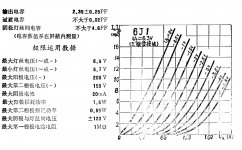
  • If I look at all the allpass filters which Doug Self describes in such beautiful detail, starting with first-order and going up to 5th and 6th order, etc, then they all give me the delay (in uSec) I've designed for, in the low frequencies, upto the "knee" with a flat phase and delay, and then the delay goes into an S-shaped curve above that point. The steepness of the curve depends on the order of the filter, but this is the general pattern.
  • Doug Self explains that we need to ensure that the delay is constant or hardly changing in the passband of the crossover branch, and if the delay is within 10% of the prescribed amount at the Fc, and is changing by 50% when the transfer function of the branch is 40dB or more reduced (due to the xo slope), then we're fine. Changes in phase or delay won't be audible if we're that many dB down in SPL.

This is all very logical and sensible. But my doubt comes from the fact that all the allpass filter circuits Doug Self shows are those which have a flat delay graph at low frequencies (see Figure 10.19, 10.23, 10.30, as examples) and show sharp delay and phase changes at the higher frequencies. Then he says that these changes are not important because they are "beyond" the Fc. This would be true if he were to apply the delay filter to the low-pass branch but actually we almost always need to apply the delay to the high pass branch, don't we? So, how can he say that "it's ok that the delay changes above the knee, after all the SPL will drop sharply beyond the knee anyway." This is just not true if we apply the delay to the high-pass branch. What we really need is the opposite shape of delay curve from Figures 10.19, 10.23 or 10.30. We need a delay curve which has a rising S shape in the lower frequencies and show a flat delay curve above the knee to 20KHz.

In other words, in real life, we need delay filters which have a series cap and a shunt resistor at the input to the opamp, not the series resistor and shunt cap. If you use Doug Self's language, then as per his Figure 10.7, we always need the CR filter type, not the RC filter type, because we always want the delay to be steady from the knee frequency to the right edge of the SPL graph, since we always need to apply the delay to the high-pass branch.

Why does Doug Self discuss all his examples the other way round, as if it's okay to have fluctuating delay and phase changes above the knee? Does he think we want to apply the delay to the low-pass branch?

I hugely respect Doug Self, own four of his books, and I can't believe he's made a fundamental mistake like this. I've been struggling to understand active filters, and I'm sure it's I who have goofed up. Can you please help me understand my mistake?

(All my references to Doug Self's book are to the 2011 edition. I believe there was a second edition 6 years after this?)

Floating Ground Adapter?

I have been trying to install a JVC reviever (cheapy) into my '87 mustang. I bought the scosche wiring kit FD021. I didn't reallize I needed a "FLOATING GROUND ADAPTER", and was wondering if I could rig or make this. I don't know much about car audio so bare with me if I'm asking stupid questions. I did search through the forums, but could not find what I needed. I know it's a cheap part, but I live along ways from anywhere I could get it.

Thanks again for the forum and all the stuff I've learned from lurking in the shadows.
Projects by fanatics, for fanatics
Get answers and advice for everyone wanting to learn the art of audio.
Join the Community
508,467
Members
7,920,862
Messages

Filter

Forum Statistics

Threads
407,831
Messages
7,920,862
Members
508,467
Latest member
AmcAmx