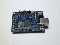
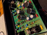
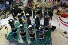
GM70 heater regulator boards.
- By v4lve lover
- Swap Meet
- 1 Replies
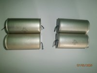
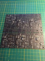
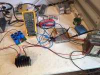
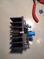
I got these Six boards from a previous batch of 20. I bothched the PCB design on two points, i drilled out the shorts and the boards should work now. Ive built multiple functioning regulators with these. I dont want to trash them, but then again i dont have a need for them.
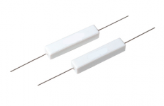
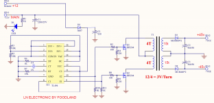
The regulator can be made to work with 10-30VDC input 2.5-27V output. About 50W of permissible dissipation depending on heatsink, and up to 7.5A current. You might need to change out the value of the potentiometer for different output voltages or change out a resistor.
The lower bound voltage input is due to the VGS requirement of these FET's coupled with the voltage drop over the sense resistors.
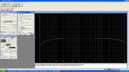
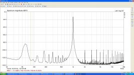
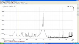
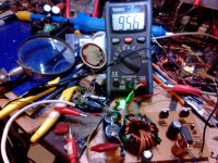
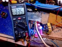
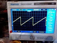
The design works but needs some refinement see my other topic. Ive got these to measure below 1mV noise. at 1V Ripple in with 20V 2A out.
You can build a dandy regulator with about 3V dropout with these. But a small modification is in order, a 2.2-4.7u cap over the gate source of the fets seems to cure any instability in the CCS.
Six boards for €5 ex postage i can supply the extra parts at cost, the FET's have a lead time of about a week. everything else i have in my part bins.
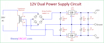
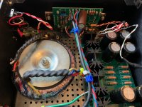
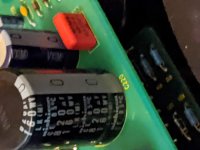
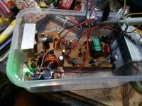
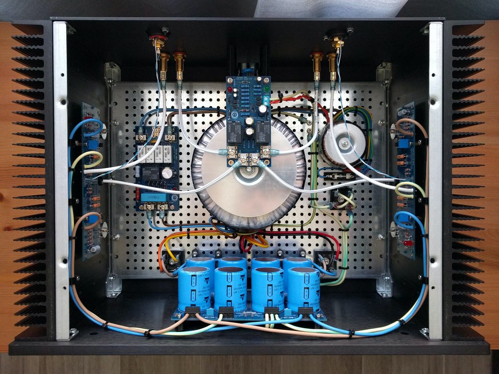
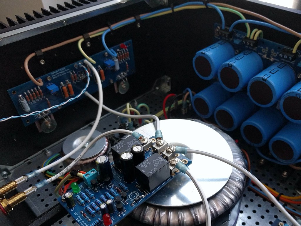
I have some quantities of the green board with rectification and capacitors available for testing purposes at a surcharge. Rectifiers are SB560s good for about 3A continuous, and 7x2200u 63V.
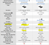
Parts needed are : 1K 0207 melf resistors, fastons some 100uF caps and LM7322 opamps/TL431 regulators in SOIC8 two 1206 decoupling caps per board and the Fets.
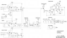
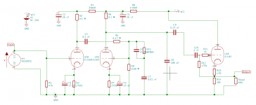
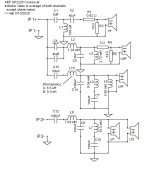
The schematic and some support is included in the price, i don't mind answering questions if you can send them to me on telegram.
Please note that i've checked the postage prices for outside of the EU and it doesn't make financial sense to send them to anywhere outside of it. You are better of asking me for the gerbers and order a lot in China yourself.
The regulator can be made to work with 10-30VDC input 2.5-27V output. About 50W of permissible dissipation depending on heatsink, and up to 7.5A current. You might need to change out the value of the potentiometer for different output voltages or change out a resistor.
The lower bound voltage input is due to the VGS requirement of these FET's coupled with the voltage drop over the sense resistors.
The design works but needs some refinement see my other topic. Ive got these to measure below 1mV noise. at 1V Ripple in with 20V 2A out.
You can build a dandy regulator with about 3V dropout with these. But a small modification is in order, a 2.2-4.7u cap over the gate source of the fets seems to cure any instability in the CCS.
Six boards for €5 ex postage i can supply the extra parts at cost, the FET's have a lead time of about a week. everything else i have in my part bins.
I have some quantities of the green board with rectification and capacitors available for testing purposes at a surcharge. Rectifiers are SB560s good for about 3A continuous, and 7x2200u 63V.
Parts needed are : 1K 0207 melf resistors, fastons some 100uF caps and LM7322 opamps/TL431 regulators in SOIC8 two 1206 decoupling caps per board and the Fets.
The schematic and some support is included in the price, i don't mind answering questions if you can send them to me on telegram.
Please note that i've checked the postage prices for outside of the EU and it doesn't make financial sense to send them to anywhere outside of it. You are better of asking me for the gerbers and order a lot in China yourself.


 ugh it hurts my brain.