Rohde & Schwarz UPL Floppy Access "Stack Overflow" Error

Since last summer, I have been unable to use the floppy drive on my UPL.

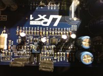
One day, everything was fine. The next day when I powered up the UPL, it had lost all its settings. I installed a Lithium battery on the digital board where one was indicated but not installed, and I was able to get the unit to remember settings between power ups. But from then forward, when I would access the floppy, the system would halt.

Today, I tried another floppy drive and I also tried it from within DOS.. just typing A: {ENTER} resulted in "Internal Stack Overflow - System halted" error.

I tried adding STACKS=12,256 to config.sys, but that didn't help.

Seems like I have a floppy controller problem.


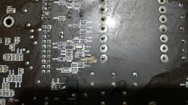
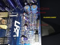
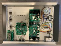
UPDATE: Problem found: Floppy ribbon cable goes to DIGITAL board, not PC motherboard. That got me thinking I need to also disable floppy controller on motherboard.

That solved the conflict.

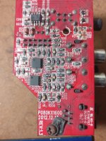
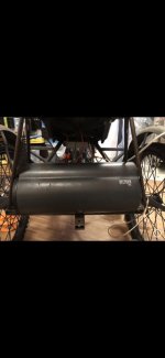
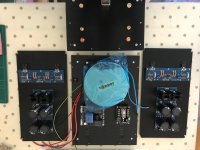
Now, I changed out the floppy drive for a Gotek USB Floppy Emulator:

Now I'm trying to make it work. I can format it in DOS, and CHKDSK thinks it's a 1.44MB disc, but but when I do a screen dump from within UPL software, it says insufficient disc space. When I read the USB on a Windows computer, it shows an empty disc.

I think one of two folks here have gotten one of these to work. If you would share what the special trick to making the UPL software play nicely with it, that would be appreciated.

EDIT 2:

Problem solved. The UPL was setup to write to a folder called \SETUPS which was missing on the newly formatted thumb drive.

Gotek USB floppy emulator installed and working!

Sound Practices CDs

Got a few mails recently from members of this forum inquiring about Sound Practices archive CDs.

I'm out of professionally reproduced CDs but would be willing to burn CD-RW copies for those who need them for $20 shipped

Paypal OK to jroberts at io.com or write for address for a check.

I am currenly in grad school studying historical archaeology and retired from the audio business. Tubes just weren't old enough for me, I guess!

Keep fighting the good fight while I'm stuck in the library!

Joe

Long tailed pair with two constant current sources

Hello everyone. I would like to know more about the transistor long tailed pair. I have seen various versions of this building block and most of them include a current mirror constant current source that replaces the emitter resistor. However, I have seen one that has two constant current sources: one in the collector and one in the emitter. Why is this useful and does it affect the quality of amplification?

Can I make use of some Electronics of old speaker system ?

Hi I have this old Philips FWD750, with three DVD , cassette players and aux input. I am just interested in using the aux input coz the whole system is ruined it works rarely, I tore it apart and found out the ADC & DAC is soldered to servo board which has a prosessor and the filters, heatsink and Amplifier is soldered to the main board. It would be perfect if i could Get it to work without removing any part just bypassing the DVD and cassete player. Incase which if its broken which is highlt priobable what parts can I salvage to hook up a aux input.

Adjustable passive radiator

Please bear with me here all. I have a pair of JBL 2269 I want to build a pair of subs with. From what I've gathered here and elsewhere is that BR and PR designs can be made to behave identically in terms of final result with a given driver, in this case the 2269.


I've discovered that shorting the driver's + and - connections with a piece of wire causes the vc to seize in the gap. This can help protect it during transport. So I'm wondering if the strength of this counter force can be varied by using a resistor instead of a wire? Further, if a variable resistor with an L-Pad were hooked up, could this then be altered 'on the fly' so to speak? If it could and a driver were substituted for a PR incorporating this system and applied to a BR box instead of a port, could the tuning be tailored for best response in a particular room with the L-Pad while listening?


If this is possible, the substitute driver/PR would not need to be an identical match to the driver making sound, and therefore cost effective, right?


Much appreciated.

Getting best audio from PC...thoughts please

Struggling to find much on this...but here goes!! 🙂


PC (MSI B360M /i5 8400 / GTX 1050ti) sends audio to AVR from Displayport, and Video by HDMI direct to TV.


Is there a better way of taking audio from the mobo (there's no s/pdif connection)??


Reason I'm looking at this is that, it seems the presence of the AVR (Anthem MRX710) seems to 'throttle' the video resolution to the TV...and this limits to 1080.


Hoped that by not taking audio from the graphics card, the screen might be 'freed up' to permit the higher resolutions it's capable of!!???


Hope that makes sense??
How about a PC soundcard with s/pdif o/p....or is that a daft way to go??

Twisted Pear Audio Buffalo-IIIse PRO ES9038

Twisted Pear Audio Buffalo-IIIse PRO ES9038

Unit works perfectly.

Build notes:
- Buffalo-IIIsePro38 2-Channel DAC w/Full Series Regulator Set
- Mercury I/V Stage
- Cronus Reclocker/Hermes/Amanero USB input
- AMB sigma11 and sigma 22 power supplies.
- Oversized, shielded transformer for analog stage
- Rear panel:
- Filtered IEC socket
- Balanced XLR and SE RCA outputs.
- USB input
- Parmetal series 20 aluminum case. 16" x 12" x 3".

- Front panel can be modified to allow for digital volume control (I will supply the relevant potentiometer), and headphone output direct from the DAC/output stage.

Asking $850 including shipping and fees.
This is slightly more than the cost for the TPA boards alone. This build cost approx. $1300

P.S life changes require full downsize of my system and projects, all of which I will be selling.

Attachments

  • 2020-04-11 18.54.01.jpg
    2020-04-11 18.54.01.jpg
    199.2 KB · Views: 542
  • 2020-04-11 18.55.20.jpg
    2020-04-11 18.55.20.jpg
    75.7 KB · Views: 528
  • 2020-04-12 00.58.17.jpg
    2020-04-12 00.58.17.jpg
    85.8 KB · Views: 557

LTspice Ncore simulation

Hello,

I haven't posted here in a while, but I do a lot of simulation with LTspice and have written a number of pages on the LTwiki including most of the Undocumented LTspice page.

Perhaps some may remember the threads on my class d Leap-Frog feedback design methods (including full LTspice models, of course). I have modeled the original UCD amplifier and run some interesting analyses of the distortion (coloration) it produces as it approaches clipping. I can't remember if I posted those models here or on the LTspice Yahoo group.

I thought it would be a fun challenge to try to model the Hypex Ncore design. My resources are the latest white paper and the USA patent. Can anyone point me to other potentially useful material? Is an Ncore schematic available? Do any simulation files already exist?

I have created a 5-pole, 4-zero (I think - haven't derived the transfer function yet) network that reproduces the magnitude loop-gain curve in the white paper. The phase response curve is not published (at least I haven't seen it), but from the simulations (both ac and transient) it is critical to always keep the zeros from drifting into the right-half plane. This is not easy to do without extreme care - kudos to Bruno.

The Ncore design is conditionally (un)stable* and can oscillate both at the intended frequency of several hundred kilohertz or at about ten times lower frequency. By shorting out the second pole pair in the feedback network one may unconditionally kick it back up to its intended operating frequency. This works well in simulation (not surprising as it is key to the operation of the real life Ncore).

The point of going all this trouble is to achieve a significant increase in (flat) loopgain across the entire audio band. When this is combined with an open-loop transfer that has been optimally linearized, the result is extremely low audio distortion without TIM or other coloration (clipping artifacts are still a weakness, at least in the simulation).

Before I upload a simulation file that is off the mark, I was hoping to collect any further detailed information available.

By the way, I hadn't really looked into the Ncore before now - Bruno is a genius.
___________________

* Not sure of the correct terminology for the fascinating feedback topology of the Ncore.

Best amplification solution for Roland TD-50 Drums

Hi all,

I'm new to this forum, and very novice on this topic in general so I appreciate any advice you can give in advance (and apologize for any missing details or misunderstandings in my post).

In short: I have a Roland V-drums (TD-50) kit that I use for practice in my house, and currently play almost exclusively though headphones. Recently, I've been considering playing out a bit (bar/restaurant type situations, so relatively small rooms). I'm trying to figure out how is best to amplify my kit so I can achieve overall good quality drum sound (doesn't have to be pro level quality though) and I'm specifically interested in making sure the thump of the kick drum and floor toms come though in the sound (not playing heavy rock/metal so I don't need the kick to be eardrum shattering), just a nice round thump.

I currently have a small EON206P Personal PA system system that I've used for playing music at small house parties, that I'm kind of hoping I may be able to utilize to some extent. However, the EON206Ps really lack any low end, and the kick sounds terrible though just those speakers.

I'm considering 2 options (although open to any suggestions):
1) Buy a powered subwoofer that I can run off a separate out from the TD-50 module to round out the low end, and rely on my current JBL EPON2016 to provide the mid-highs.
2) Buy a slightly more all-purpose speaker that will add more low end, but also provide some support in the mid-range and overall amplification.

I'm trying to keep the budget under a max of $700 max for the final solution.

For Option 1 I've come across a few different subwoofers online:
1.)Mackie Thump 18S - $699 US
2.) Harbinger VARI V2318S 18" 2,400W Powered Subwoofer - $599 US
3.) JBL EON618S - $699 US

For Option 2 the options I'm considering are:
1.) Mackie Thump 15A 15 in. Powered Loudspeaker - $349 US
2.) JBL EON615 - $399 US

My main questions for anyone who is willing to give their input on this are:
1) Does the Option 1 solution with a subwoofer paired with my current EPON2016 personal make sense or does this seem weird to add a powerful subwoofer to a very underpowered personal PA system? Again, I only need enough sound for a small room with 20-30 people, but want to make sure I can get a little tump from the kick drum.

2.) In Option 2, do others think that the 15" powered speaker options that I linked to would have enough low end to provide the desired kick drum thump?

3.) Are there other speaker options/combinations that I haven't mentioned that would achieve the desires result in the same basic price range? I do want to stick to relatively reputable & quality manufacturers (not looking for total low-end band/quality just to keep the price down).

Thank you very much for any input you can provide and please let know if there are any other details or missing info I can fill in!

Cheers,
Nick

converting channel fader to rotary pot

Have a Allen and Heath Xone 02 dj mixer. It's a 2 channel mixer, each channel stereo. I want to add pots to it to control each channels volume. I took it apart, The channel faders sit on a pcb, with 4 pin connector on it. What I don't fully understand is how the channel fader works with 4 wires, instead of the normal 6 wires that are standard on like a ALPS RK27. Can anyone help me make sense of that?

:cop:

Mod note: Please upload images directly using the advanced editor instead of hotlinking to other sites, thanks!

:cop:

TL with Dayton DMA58-4

Seems like these tiny drivers might be fun, at least down to 150hz where 2mm xmax is exceeded. The xmech seems to be just over 4mm, so maybe even useful to 60hz with more distortion?
Am I mistaken and missing something? This is vastly better than sealed or ported sims out to?

Attachments

  • Screen Shot 2020-04-24 at 6.03.20 PM.png
    Screen Shot 2020-04-24 at 6.03.20 PM.png
    126.2 KB · Views: 98
  • Screen Shot 2020-04-24 at 6.03.05 PM.png
    Screen Shot 2020-04-24 at 6.03.05 PM.png
    228 KB · Views: 92

I have a chance to buy B&G RD-75's's

Hello, I have found someone with some original "NOS", Bohlender Graebener RG-75's OR RD-75's OR 1.9's. does anyone know the differences in these models? I am wondering which is better for a home line source. And overall what the difference were. I was reading recently about a fellow whom built a line source back when the RG-75 was first manufactured. He raved about it. But I am taking that with a grain of salt. I do know I would like to try it but I do not know much about them. Other than 6'-3" tall and can be run from 150Hz - 40KHz. At least that's what I have read. I cannot find too much on-line about them. I'm wondering if this is a deal or a bust. ANY help/info would be highly appreciated.

I am currently working on developing a line source speaker using the B&G Neo 3, Neo8 and Neo10 so I have a little experience with them but the RG-75 sound like the "pinnacle", of what B&G's, R&D came up with and actually manufactured. Even though only for a limited time.

s-l1600.jpg

FS: Valvo ECL86

I guess like most people atm, I am cleaning up the office/workshop
1 x Original Valvo ECL86

Pulled from a Grundig 3010H which was in absolute MINT condition.
The radio is not for sale (or do me a REALLY good offer)

The tube is tested and measures still really really fine.

Price: 25 euro excl shipping

I am based in Europe

Attachments

  • ECL86_valvo.jpg
    ECL86_valvo.jpg
    411.9 KB · Views: 114
  • 1.JPG
    1.JPG
    171.1 KB · Views: 115

F5 bias and thermal issues

hi - i am about to finish my F5 build but obviously i did it first without thinking! My layout is as below. I think i am going to have two issues 1) bias - but i thought i could get away it it by biasing the amp as shown and then put it back together after. I know that you suppose to wait for 2 hours with the lid closed so this could be a problem

2) the f5 board may not have enough ventilation because it is mounted vertically near the transformer at the back. Is this going to be a problem? I don't know if it makes any difference mounting it this way

at the end of the day, if i have to redrill and tap again then i will do it. i could put the PSU in front of the transformer and use two monolithic diodes instead to save space (I have the KBPC3510). Is this ok?

I heard that it gets very hot and the JFETs will blow so i don't want this to happen.

Thank you very much for any help

Philip

Attachments

  • IMG_1838.jpg
    IMG_1838.jpg
    558.3 KB · Views: 255

Interest for potential GB for UDNess PCBs and matched FETs.

This is my first attempt to organize a group buy. I'm offering a lot of transparency re: how I think this could work (or not), so if there are constructive thoughts to make it a better experience, please share.

See Original Thread

UDNeSS, or You don't need Semisouth's

This thread is to gauge interest. I'll also hear any advice or requirements for matching parts. I've offered my thoughts, but I'm pretty flexible. I'm also very new to DIY and electronics in general, so I may be wrong 😱 in some cases.

I would be willing to buy and distribute (in the lower 48 only) a set comprised of -

2 - main board PCBs - using Patrick's Gerbers
2 - supplemental boards allowing use of 2SK209s for Q2, Q3 - using Patrick's Gerbers
4 - (2 matched pairs) Fairchild Mosfets FQA9P25
8 - (2 matched quads) 2SK209BL
2 - J113 with min 8.5 Idss

I'd be willing to match / sort parts for up to 10 sets / 20 channels. I'd be willing to order parts and distribute up to 20 total shipments. If in addition some people wanted boards, but no parts or boards and a pile of FETs to match themselves. Fine by me. I'd base it off interest. To keep it fair, I'd initially limit it to one set of boards and/or parts per person. I'm not going to donate my labor to one person that wants 20 channels. They can sort their own parts. :rofl:

re: MOSFETs matching.

I researched across the forum. There seems to be a lot of discussion around the process to match these parts and parts like them. I would match the Fairchild parts @22V0 / 1A4. Matches within 5% should be achievable with a decent yield. I usually match parts like this without a heatsink after 30s. I'd be willing to use a heatsink jig with clips and take the measurement at 1min. If it's simple and improves reliability / confidence, I'll do it.

If a heatsink is used I will start all parts at roughly the same room temp and take the measurement within a second or two of a given time after the voltage is applied.

I will not:
bolt each part at a standard torque using a specified washer area to deliver the precise thermal coupling;
keep a heatsink at a known temperature;
allow the heatsink to cool between measurements;
use anyone's favorite thermal compound;
use new thermal compound between measurements;
or guarantee timing to the ms.

I'm not willing to go to that level of effort.

In a different field, I've done extensive work determining the precision and accuracy for standardized test methodologies and instrumentation. I've also determined the expected variation within, between, and overall among operators trained in standard methods using standardized samples with standard / calibrated instruments. From what I've seen in the threads - even if I tried to improve the accuracy of the measurement by using heatsinks, it probably would not result in a more precise/reliable match. We're looking for matches, not the absolute value or accuracy of the measurement at operating conditions. We're assuming that if parts match under certain reasonable conditions when measured a certain way - that they will also match under the actual operating conditions closely enough. I actually find it interesting when people record the values to 4 significant digits. My guess based on matching about 100 similar devices, is that the measurement error alone may allow a precision closer to 2. If that's a dealbreaker for some people, no worries. I'm willing to do the work within reason. I also love to learn. So, if there's a measurement method that can be accomplished in <5 mins per part that results in more reliable matching - send it my way with your thoughts as to why it would ensure a better match. I'm not interested in theory re: why it would provide a more accurate absolute result. I understand that already.

I appreciate Patrick's policy of not providing matching data. I will follow suit. My commitment will be to match the parts to an agreed process. Providing values for each part will only serve to cause confusion. IMO, there is just too much potential variability in the measurement methodologies to provide an absolute measurement. If I write down 4 values of 4.44, 4.44, 4.45 and 4.46 - then someone measures them at home and finds... 4.31, 4.32, 4.35, 4.38. I'm not willing to deal with the potential outcry.​

re: 2SK209s

I would match using this jig recommended by Patrick
Peak SOT23 Adapter for Testing Parts on DCA55 DCA75 Model PCA23 Atlas | eBay

It looks nifty. I'll buy it and not pass that cost along. I know I'd use it for other projects. I have a pile of BF862, and I'd have loved to have this jig when matching those! I'd also consider providing 2 matched pents. They're small. There's a reasonable likelihood that someone is going to drop one... damage one etc. There's no way I could send out a replacement part with a known value. OK. I could, but I'd charge A LOT for that. If I get enough parts, and the values match tightly enough, I'd just send along pents vs. quads.

re: J113s
I'd sort all J113s >8.5mA IDSS, then pair them off by the closest values.

Goals
My goal is to build a couple working channels for myself, give a bit of my time back to the community that's been so generous to me, and maybe save a few of you a buck or two and a lot of time.

The first question I anticipate is cost. I have no idea. I've never ordered PCBs. I'd calc the costs as such:

  • PCB cost goes to each person. I'd likely round it to some clean value erring on the side of value for the buyer.
  • Total cost of all the parts gets divided among people that want them. I've been told to expect ~20-30% yield. I'd order about 5x the number of parts on the conservative side. Given the cost discounts at volumes, I think it's still cheaper than buying just the number of parts required. Again, I'd likely round to a simple number erring on the value going to the buyer.
  • I'd ballpark shipping and packaging (based on similar GBs I've participated in) at about $7 per order. I will charge a flat rate just to make it easier for me to collect payments. Don't gripe if your actual shipping + envelope is <$7, and be thankful if yours is > $7.
  • My labor and other parts / jigs I'd buy or build - no cost passed on.
  • The experience of building this fantastic design at such a low cost - priceless 😀

I had posted in the other thread that I'd send out all remaining unmatched parts to the group. I was told that was not wise. So, I will follow the advice and not send out unmatched / unused parts. However, like with the 2SK209s if I have enough matches to provide an extra or two, then don't be surprised to find a lagniappe in your goody bag.

Thoughts? Interest?

:cheers: to Patrick (@EUVL), @Morde, and a fantastic DIY community

JL Audio 900/5

Hi guys,

this amps doesn't turn on but the power supply is ok because all voltages are present and correct (+15, -15, +5, -5 +35 and -35) with an idle current about 2,5 A.

I think there is a missing connection because the "big hole" at center of the mother board. Problem is i dont't have any schematics of information about mother board traces

But this amp have a "three slice" board ? Because surface is connect to ground, just a little bit inside the board (if i put a tester plug inside the hole) there is a +12 V ....

Thanks for your help.

Giovanni

Attachments

  • IMG_20200423_180010.jpg
    IMG_20200423_180010.jpg
    851.8 KB · Views: 100

Dynacord LSW

Hello people. i want to decide what pair of subwoofers i should build (teknival and edm ussage). I saw a plan from dynacord and seems preety simple to make. My question is: Did somebody hear or saw a builded one? I couldn't find anything on internet exept the plan. Or, how this planar will sound in comparation with a th18, bph or a scoop (my other choices for the build) The drivers will be 18tbx100 or void v18
I have a small dual 15 planar box but i can't hear a big difference than a br box, maybe a lil bit in directivity. Goal is @40 hz flat; or less.

I'm really into this project for the simplicity and the size of it (i can easely put a fullrange on top and will be at head level)
998256_494937583911720_1365378691_n.jpg

How to optimize enclosure for mini speakers in WinISD?

Hi guys!

I'm trying to learn how to better optimize sound for small speakers like in gadgets, etc. I picked this small speaker online just to learn, and the specs gives very little T/S parameters.

A38K 1/2" Mylar Cone Full-Range Speaker

I'm able to input the driver like so in WinISD, and I can create a new 'vented' project. But for a 'closed' one it fails and says it's out of bounds. Do I need to guess other parameters or am I missing something?
An externally hosted image should be here but it was not working when we last tested it.


Thanks!

Any 3D printing enthusiast here?

Hey guys,

I am a proud owner of a Makerbot Replicator 3D printer but II need to go bigger. I want to purchase a large-format device, I am really happy with my Makerbot printer and already had a look at other own-brand model but, unfortunately, I need a build volume of at least 400x400x400 mm, which lets me produce bigger parts in one go, without splitting them.

I've always printed with Makerbot equipment and choosing a different brand is now driving me mad. I came through this interesting article and, among all the suggested models, both the Modix Big 60 and GCreate Gmax 2 caught my attention for their printing accuracy and large sizes. Does anyone here have any experience with large format 3D printers? Any tips/gotchas I should look after to?

Sorry for the offtopic. Hope someone might help me.

Any advice is warmly welcomed.

Thanks, Adam

Enclosure size for Tymphany TC9 FD-18-08 used as "tweeter"

Hi Gents,

I am going to be building a pair of somewhat unusual two ways soon. I have talked with tech support at Parts Express and they say that they think my idea will work but could not advise me as to some of the details of the build.
Specifically, I plan to use the PE 8" sub woofer part #295-484 crossing it at 500HZ to a Tymphany TC9FD18-08 PE part #264-1062. The planned crossover is the "textbook" hi pass of 5mH coil with 20uf cap and low pass of 2.5mH coil with 40uf cap.
This is not intended to be a great sounding speaker overall. It is more of an experiment to see if these super-affordable drivers can be paired to make a reasonably clean sounding speaker with very good bass.
I can come up with a pretty good ported cabinet design using WinISD Pro but as the thread title suggests don't have a clue as to the best size for the TC9FD "tweeter" chamber. PE tech support suggested .1 CF but that seems way to big for a driver being crossed over at 500HZ. In fact I'm wondering if a chamber is needed at all since the woofer is rolling off at 500HZ and the back of the tweeter cone may not be much affected by such low frequencies.
So, do I need a chamber and if so, what size?
Also is anyone aware of a "quick and dirty" crossover that would be a substantial improvement over the textbook one for these drivers in a project like this?
Again, I realize these are not going to sound great and know that "textbook" crossovers are not optimum, but I am eager to throw these together and see how they sound. All constructive input is very welcome and appreciated.

Best,
Jay

Beard P35II tube amp repair capacitor questions

Hello all,

Couple of months ago I fired up my Beard P-35 II for the first time in too many years. Probably 15 years ago I replaced the known failure regulators with higher rated models, then had no further problems for a good while.

When I hit the power switch, the 500MA fuse HT fuse blew on one channel.

I suspect the 47uf electrolytic between the power supply and audio circuit, so I ordered 2.

While looking inside, I noticed that these (pic) capacitors look bad. Have ordered these: DME4P1K-F Cornell Dubilier - CDE | Mouser.

Could anyone jump in and confirm the choice? I did not know what the marking "fo=4.9MHz" on a capacitor is intended to represent? Looks like it has been hot around there.

Thanks for any additional insight - Robert

Attachments

  • IMG_20200419_111343 sf.jpg
    IMG_20200419_111343 sf.jpg
    49.8 KB · Views: 167

Question about port

Hello,

I am using QSpeaker to design my ported enclosure. For this example i will be talking about built around Dayton TCP115 8 ohm, 2.3L enclosure and 65Hz resonant frequency. All well. Now to port.

The program will give me port diameter of 3.2cm and length roughly 22cm. All is well. Now i want a port of diameter of 2cm and it will give me length of around 8cm. But now if i change volume of enclosure, it will again set the port diameter to 3.2cm, which seems to be the programs favourite diameter.

So my question is this. Am i perfectly alright using 2cm diameter port of length 8cm, even though program seems to favor 3.2cm x 22cm ? I read that larger diameter results in less port noise. But as far as F3, will the 2 roughly compare the same ?

The reason i am asking is that shorter port is easier to include in this small enclosure than a large port and i would like to know if i am losing bass due to smaller diameter or i am not.

Helix Dome speaker build

I just finished building a pair of these (Denovo Audio Helix Dome MT). I veneered them with red oak and then finished with polyurethane.

I ordered the crossover PCBs (which at $9.25 each are pretty much a no-brainer for this kit), but I didn't like the idea of just mounting them via the four corner mounting holes so I 3D printed a holder. The crossover has some pretty heavy parts, so I designed some additional supports into my holder and used two-sided tape to seat the board onto them. I also put a thin piece of compliant material between the holder and the bottom of the cabinet to eliminate any change of the PLA plastic buzzing against the bottom of the cabinet.

The cabinet itself was quite an adventure. I ordered some paper-backed red oak veneer with the PSA adhesive from veneersupplies.com. I was nervous about applying it to the front panels included with the kit since I didn't have a router to do the cutouts, so I re-made the front panels out of two pieces of MDF (1/4 + 1/2") using a desktop Shopbot at my local makerspace. This allowed me to put reliefs in the back of the front panel to seat the adjacent four sides plus the brace into, which should make for a slightly stronger cabinet than the front from the kit which is just flat on the back. It made for a fun hobby project and a good intro to the shopbot, but it was a lot of work.

I used Sonic Barrier 1" foam to line the inside of the cabinet (the stuff with the PSA from Parts Express). It's super easy to work with and I highly recommend it for this sort of thing.

I eventually ended up getting a small router to trim the veneer. I purchased a small saw from the veneer supplier but this didn't work very well - I ended up using a utility knife, the router and a small trimming plane to clean up the veneer prior to final sanding. The PSA adhesive worked out pretty well, but I did have a tiny bit of peeling I fixed with some wood glue.

I tried a bunch of different stains but I didn't find anything I liked better than just Varthane water-based polyurethane over the bare (sanded) veneer. Three coats of this came up really nice and it's great that it has basically no odor after just a few hours of drying.

The speakers sound great. Really smooth with a surprising amount of low-end. I've been going back and fourth between these and my old B&W P5 3-ways for the past couple of days (with both sitting side-by-side driven from the same Marantz PM8004). I still prefer the P5's just slightly - the sound is fuller with a more musical midrange - but the Helix Domes are close (and this is with basically no break-in).

Some other things I found useful:
KabelDirekt AWG 16 Speaker Wire for internal hook-up (a little overkill, but it's cheap and one strand is clearly labeled with a red stripe)
McMaster Carr 91555A102 and 91555A104 screws for attaching the crossover board and my holder
Tite-bond wood glue
Lots of clamps from harbor freight
Buck Bros 3" plane model 120LSO from Home Depot, sharpened with a diamond block from Harbor Freight
Bosch Variable Speed Fixed Corded Router PR20EVS and 85268MC flush trimmer bit

Attachments

  • IMG_20181210_104906098_HDR.jpg
    IMG_20181210_104906098_HDR.jpg
    399.5 KB · Views: 449
  • IMG_20181210_182857409.jpg
    IMG_20181210_182857409.jpg
    348.5 KB · Views: 455
  • IMG_20181210_182939405_HDR.jpg
    IMG_20181210_182939405_HDR.jpg
    290.5 KB · Views: 453
  • IMG_20181215_135142982.jpg
    IMG_20181215_135142982.jpg
    482.2 KB · Views: 463
  • IMG_20181215_164037527.jpg
    IMG_20181215_164037527.jpg
    344.3 KB · Views: 452
  • IMG_20181215_210018165.jpg
    IMG_20181215_210018165.jpg
    304.8 KB · Views: 263
  • IMG_20181225_114815413_HDR.jpg
    IMG_20181225_114815413_HDR.jpg
    152.9 KB · Views: 234
  • IMG_20181230_204034972.jpg
    IMG_20181230_204034972.jpg
    378.9 KB · Views: 378
  • IMG_20181230_205608418.jpg
    IMG_20181230_205608418.jpg
    201 KB · Views: 307
  • IMG_20181230_205554923.jpg
    IMG_20181230_205554923.jpg
    276.6 KB · Views: 333

very simple class d amplifier made of standard devices

I have drafted a class d amplifier with a minimum of standard devices.

The PWM consists of 2 rectangle generators, each based on a timer IC NE555 (U1, U2) working with the same current regulator diode E-102 (I1) and the same capacitor (C1).

The first timer (U1) is in astable mode, generating the trigger signal with a frequency of 500 kHz for the second timer. The second timer (U2) is in voltage controlled monostable mode. It converts the signal voltage (V4) into a pulse width.

In a stereo amplifier the first timer is only needed once, because it can trigger the monostable timers of both channels.

The pulse width modulated signal is fed into the input of a half bridge driver (LM5104) which controls the gates of the power output stage (M1, M2). A low pass filter (L1, C4) with a roll off frequency of 40 kHz converts the amplified PWM signal into a continuous voltage at the load resistor (Rload).

What do you think about this design?

Attachments

  • class d amp.jpg
    class d amp.jpg
    270.2 KB · Views: 386

Home Theater Sub Monarch SP-400HT

Hi everyone,


I made an account here after being a long time lurker.
I have a problem in that i am trying to create a sub enclosure for an SP-400HT and can't find a lot of info. The info that i find, i don't know if it is correct, but is as follows:


Impedance: 8 ohm
1 W / 1 m: 98 dB
fs: 21 hz
Vas: 410 l
Qms: 6.55
Qes: 0.25
Qts: 0,24
Re: 6,4 ohm
Sd: 855 cm²
Le: 1,6 mH
Rms: 1,7
Mms: 85 g
B * l: 16.9 Tm


When i give this in winisd, i get an enclosure of around 100L but the -3db is above 50hz 😱


Right now it is in an old enclosure i made when i was a teenager, around 140L and two short big ports, really not optimal, but it was on a serious budget 🙂


But it plays... not bad, and certainly lower than 50hz -3b, it goes down to 30hz pretty easily.


Maybe this is a sub made especially for PA and thus doesn't get really low?
I was wondering if someone with more knowledge here could help me out, thanks in advance! 🙂

layout check before I drill & mount parts

Please have a look at my description & pics below - any guidance/tips would be great! (this is my second amp, its for a subwoofer)


I have settled on this cable routing layout for the parts I am using - it is built on a 300x300mm 3mm aluminium sheet.

the AC starts close (50mm) to the 50-0-50 toroid, then the secondary output gets to the rectifier via about 50mm of wire (twisted), this rectified power goes to the capacitor PCB via about 70mm of twisted wire.

then the power leaves the capacitor bank (which has 100nF capacitor in parallel on both sides) and goes around the top and back down to the amplifier PCB, where there are chassis fuses within 5mm of the PCB power connections.

the 0V of the capacitor PCB goes:

  1. back to the chassis (near but on on the IEC earth bolt)
  2. to speaker out
  3. to amplifier 0V
the speaker ground follows the path over and around, and i wanted this away from the rectifier, so it has followed the power wiring - is this OK?

there is a speaker protection circuit right next to the output posts


the input wires will be shielded coax from the back panel that travels about 80mm against the side wall of the chassis.

there is a small 12VDC transformer there for the 80mm TC fan that will sit up at the top in front of the tunnel heat sink - blowing out the rear.

this 12VDC also powers the speaker protection - which will follow the 'up and around' path of the other power wires.


is this wiring plan flawed anywhere or will it be a suitable wiring layout?
attachment.php

attachment.php

Attachments

  • wiring plan.jpg
    wiring plan.jpg
    78.3 KB · Views: 323
  • actual parts_v1.jpg
    actual parts_v1.jpg
    730 KB · Views: 326

Problems with IRS2092??????

i bought a kit from sure electronics it worked well....then i thought to take the voltage readings so that i can make sureness when i build my own one if it is correct or not.....i took all the readings but when i went to take the reading of vcc mistakenly the probe touched to VS pin but dint short to vcc and the amp turned dead....i tested this thing on one side of the board but the other side also was off after that dont understand why is it so.....

NEED HELP,,,,,any feedback would be highly appreciated

Faulty Class T/D amp

My new Chinese ClassT/D amp is faulty on one channel. Something in the back of my rig popped and exploded but my wife heard it and wasn't sure if it came from the power point or the amp itself. Nothing happened to any of my other amps just the Chinese one.

Immediately after this on the front of the amp the "mute" light indicator came on the side which was already showing a significantly less power output with the light indicators when playing. What I mean is the row of lights on this side was one bar less then the other side and still is.

Now, the amp is playing but I can prove that one side is playing my sub with one note bass. As soon as you go the good side the tightness is just something else. I can guarantee this is no a figure of my imagination there really isn't any other way i can describe the fault. Even at full range its playing but i feel that its playing backwards with the bass notes and nothing like the other side.

Anyway, can this be fixed by an amateur? And is the problem obvious and something obvious I can check?

Soft switch version 2 anyone?

After the first group buy of the soft switch circuit, I continued to get emails from people interested in the kit. I've made a version 2 which includes the following improvements:

1. Replace the hard-to-obtain MAX6816 (debounce IC) with a CD4013.
2. Added a high current relay to switch up to 15A AC.
3. Added jumpers to make one board work with 115VAC and 230VAC.
4. Added an NTC thermistor for in-rush current limiting. The layout supports the popular CL-60 or larger CL-101 part.
5. Added a fuse (15A max) for the switched output.
6. Added an output for an optional current-limiting board.

You can find more info and pictures on my website: http://www.robcheng.com

Click on AUDIO -> ELECTRONICS -> SOFT SWITCH V2

Here is preliminary pricing:

$55 shipped (U.S.) includes everything.
$40 shipped (U.S.) minus the switch.
$15 shipped (U.S.) for PCB only.

International: add ~ $5-$10 depending on location.

The prices are higher than the previous GB because I'm including the transformer and high-current relay.

Please post or email if interested or if you have any comments, suggestions, etc. As interest grows I'll create a Wiki page.

Buying some new PCB/drilling equipment. Advice needed

Hi,
I've just bought the equipment needed to make PCBs using the photo-resist method. Until now I've just either used stripboard or had boards made for me. I'm now looking at what tools to buy next and was hoping for some advice/ recommendations on which route to take.

I need something to drill PCBs, something that can drill enclosures and something that can cut square holes in metal for IEC connectors etc.

So far I've come up with the following options:

Proxxon 340/E drill/grinder with MB 140/s stand: For drilling PCBs and using a cutting disc for square holes in metal (as far as I can tell, it can do this.)

Clarke CDP5EB pillar drill: For drilling holes in metal chassis.


I think this would cover my different needs but is a fair bit to buy at once.

My other thoughts were the Proxxon TBM220 bench drill for PCBs and I wondered if it would be capable of drilling chassis too.

Another option would be to go with the Proxxon mini drill and stand and stick to using a hand drill and stepped bit for chassis holes. I can never get the holes to line up dead on though, hence my desire to upgrade!


Anyway, what do you reckon? Does this seem sensible or are there some better options that I'm missing?

Thanks,
James

Guitar amp presence/feedback RC network from 15om to 4om - needed help

Hello,

I've made a replica of Selmer TV10 guitar amp recently, but, since I couldn't find any schematics of it, I based on TV15's one (attachment), because TV15 is just bigger TV10. One thing I didn't realize is that TV15 has 15om speaker whereas TV10 has 4om. As a consequence presence/feedback control (aka "Tone"; in red circle) is not working properly, due to lower voltage. Can someone help me to redesign that RC network to match the lower impedance and keep its original sounding?

Thanks for any response.

Attachments

  • tv15.jpg
    tv15.jpg
    237.9 KB · Views: 71

active crossover: fir vs iir

i'm going with an active setup using a computer and vst software to do my crossover, and am currently planning on using a l/r vst plugin filter. it's my understanding that the disadvantage of iir filters is phase shift (90* every 6dB/oct of slope), and that fir filters have no such phase shift.

but what if you just use a 24dB/oct (or a multiple thereof) slope? that's 360* of phase shift and thus no phase shift -- correct? even if i were to use a 12dB/oct or 36dB/oct slope (180* of phase shift), couldn't i just reverse the polarity of the mid and end up with the audio back in phase? is there anything wrong with my thinking on this? ..or is there some other benefit of a fir filter over an iir filter.

thanks,


-chris

PCB design trade-off

I am making a layout for my active crossover as shown in the attached photo. In addition to op-amps in crossover, there are three more dual op-amps for balanced input stage biasing. With many modern op amps in a PCB, I decide to make a 4-layer-PCB layout with ground plane on layer 2, Vcc on layer 3 and Vee on layer 4.

Here I have a problem with capacitor. The capacitor in crossover is rather large in order to keep the resistance low enough. For 4.7 uF I have no choice but to use through hole capacitor (Panasonic ECW-FD)

For other capacitors, I have two choices:
1. Through hole film capacitor like Wima FKP3 or Panasonic ECW-FD. They are pretty compact and have very good characteristics. But since they are through hole part, it will create holes in ground plane. So many of them will make my PCB like a Swiss cheese.

2. NP0 (C0G) SMT capacitors: they have great characteristics, small, low inductance, don't interrupt the ground plane. But from measurement by Vicnic in "Low distortion oscillator" topics, their THD is slightly worse than some THT film caps like Wima FKP3.

There are film SMT capacitor in PPS dielectric, but they are worse than C0G ceramic and Polypropylene THT caps, so I don't want to use them.

Since I don't have much experience in analog hardware design, I would like to ask you folks which type of caps I should choose in my design, C0G SMT with an unbroken ground plane or THT film capacitor with a broken gorund plane.

Thanks,
Trung
Frage.png

Mic Mute Pedal - Phantom Power and LED

Hi,
I built a Mic Mute pedal for Condenser microphones, and I used this circuit:

1VNwPbY.gif


It works great, there's no pops or clicks when switching.

But as I use it in live sound on a stage I would like to have 2 LEDs, one red to indicate MUTE position and a Green one to indicate ON. I would like to draw power for the LEDs using the phantom power supply so that no battery or external supply is needed.

Whats are your advices on how to add the LEDs supplied by the Phantom Power without introducing Pops/Clicks when switching
the ON and OFF/MUTE?

Thank you so much for your help

Dual voice coil wiring question

Hello,

so I have one Dayton Audio SD215A-88 in my DIY multiway and It is definetly reaching pretty close to the Xmax at about 40W, which is why I'd like to raise the impedance.

So my question is, would leaving only one coil connected change the T/S parameters in any way, should I wire it in series (not optimal as that would give too little power).

The driver has 80W RMS, playing 40W seems to be enough for the mechanics.
It has 2 VC, 2x 8 Ohm.

The box is 130 liter ported enclosure tuned to 28 Hz.

Subwoofer Link: Dayton Audio - SD215A-88 8" DVC Subwoofer 4 Ohm

Unknown power of particular toroidal transformer

Hi guys,
this is my first thread 🙂

I am building a LM1875 dual mono amplifier (it is a cliche I know, but it is what it is) and I have a rough time finding adequate transformer for it.
I live in Bosnia and there are no specialists who produce transformers (as far as I know). Then few days ago I found this toroidal transformer.
It's been taken out from some brand name audio amplifier, but I don't know which one.

transformer1.png


transformer2.png


Now, on the label it says 2A along with some other info. Does this mean that this transformer can output just 2 amps of current or this means that I need 2Amp fuse for it?

Basically, is this transformer enough for my amplifier... It is about 11cm (just over 5 inches) in diameter and it's 1270g (just over 2 lbs).
When I use it with my LM1875 test amp, music sound great to me. I don't hear any distortion even with volume all the way up.
Thank you.

difference measuring DC offset with and without source

I have built a headphone amp with an bipolar opamp for voltage gain and another as a buffer. Nothing special I think but it has no input capacitors because I want to test it without.

It works but when I measure DC offset at the output without a source I get 77mV.
When I connect 10k at the input I measure 5mV.

Why is this? Without anything connected at the input I can imagine it picks up mains hum and such but then I would expect more AC than DC at the output.

Can anyone explain this to me?

Thanks,

regards,

Cor

Kicker 40KX12001 preamp board components?

Kicker 40KX12001 schematic? (or any available preamp boards?)

Have here a Kicker KX1200.1, model number 40KX12001, so it is the newer model to the one with all the posts on here. The preamp/RCA board has sustained some (water?) damage and some of the resistors, capacitors and ICs need to be replaced. Most of the resistors and ICs can be identified by their markings, but I am unable to identify the correct capacitors and also a few missing components. If a schematic is available, I would be able to help myself. Also, if this part is available for purchase anywhere I would also be interested in that...

My questions are:

What should R215 be? (missing)
What should C204 be? (missing)
What are all the other capacitor values?


Any assistance rendered would be much appreciated...

Attachments

  • IMG_20190906_210012.jpg
    IMG_20190906_210012.jpg
    741.4 KB · Views: 134
  • IMG_20190906_210815.jpg
    IMG_20190906_210815.jpg
    866.9 KB · Views: 136
  • IMG_20190906_210756.jpg
    IMG_20190906_210756.jpg
    696.3 KB · Views: 124
  • IMG_20190902_014904.jpg
    IMG_20190902_014904.jpg
    776.2 KB · Views: 124
  • IMG_20190902_014946.jpg
    IMG_20190902_014946.jpg
    774.6 KB · Views: 71
  • IMG_20190902_014917.jpg
    IMG_20190902_014917.jpg
    809.6 KB · Views: 80
  • IMG_20190902_014849.jpg
    IMG_20190902_014849.jpg
    679.6 KB · Views: 84
  • IMG_20190902_015102.jpg
    IMG_20190902_015102.jpg
    810.3 KB · Views: 84
  • IMG_20190902_014833.jpg
    IMG_20190902_014833.jpg
    987.3 KB · Views: 136

EKIO and Focusrite Scarlett 18i20 (3rd Gen)

Hello,

I am planning to build stereo 4-way (8-channel) multi-amp audio system with EKIO and Focusrite Scarlett 18i20 (3rd Gen). Of course I will use suitable 4 stereo amplifiers or 8 mono amplifiers.

I understand that EKIO will enable stereo 4-way (8-channel) crossover on Windows 10 Pro 64bit PC Workstation with Focusrite Scarlett 18i20 (3rd Gen).

I would appreciate suggestions on the most suitable S/PDIF 192 kHz equipped audio interface board with which I may easily configure stereo 4-way crossover system; I am now mainly using Roon.

Can a small inhomogeneity in the voice coil cause audible distortion (in a sub)?

I was winding a 40 mm diameter coil with 28 AWG wire for a ~ 6 ohm sub (4.2 ohm DC resistance). The coil is 25 mm tall, with 2 layers.

However, due to some misalignment I had to skip one wire width for half a turn in the middle of the second layer.

This means there is something close to half a turn less in that region.

The gap in my magnet has a depth of 5 mm, which means that there would be an average of 31.25 turns "inside" it at any time (considering the 2 layers).

So, with that part well immersed in the gap (it happens to be just above the gap at rest), the Bl factor could be 1.6% less than when this part is well outside the gap.

I know B doesn't change instantaneously in the extremes of the gap, so that should smooth things a bit. But yet I'm not sure of how much this will impact the result in the end.

Do you think there's any chance there will be audible distortion due to that?

Noting that this sub will work between 20 and 80 Hz.

Thanks!

How does a mains Automatic Voltage Regulator work?

Hi, I’ve been looking at for example Powerwalker AVR (Automatic Voltage Regulators) units. They are not very expensive and provide a more stabilized mains voltage. I’m curious how they make it work. Given the price there cannot be too much magic inside the box.

Regards, Gerrit

Attachments

  • FA50DFE6-7CCD-4014-BBE4-88D2CA5642EC.jpeg
    FA50DFE6-7CCD-4014-BBE4-88D2CA5642EC.jpeg
    28 KB · Views: 236

Tube Preamp -> Power Amp (Impedance Matching Question)

Hey, I recently picked up an ICE Power 100AS2 100W Solid State Power Amplifier Module and I'm trying to build tube preamp for it but having mixed success.

The board itself seems awesome, very strong. Hooked up my signal generator and easily putting out 100W with a 10VAC signal (measured signal to ground).

I built a two stage tube preamp that displays the characteristics I'd like but when I connect the 2 I'm getting significantly lower output power (~40W). Unconnected, the preamp signal can get up to 80VAC (measured signal to ground) but when I attach the tube preamp output to the board's input that signal drops to ~6VAC. I don't have a ton of experience with solid state, but this sounds like an impedance mismatch or something like that?

My 12AX7 has a 100K plate resistor and .022uF coupling capacitor. I've changed the resistor's value (to ground, after coupling cap) from 10K - 1M and nothing really changes. Even removing the resistor didn't do much. Also, I'm taking the output from the preamp at the connection of the coupling capacitor and resistor to ground.

I've done a few calculations and sounds like my output impedance is ~40K...From the ICE's Datasheet, the input impedance is 2.8K, so it sounds like I have greater than the 10x output/input ratio I've seen suggested.

Please let me know if anything I'm doing sounds obviously off. Thanks!

Upgrade to a TPa3255 for my Trike build. Any for sale?

Hello everyone,

I am currently looking to upgrade my current sound system I built on my electic tricycle. Im upgrading my motor from 48v 1500w to a 72v 3000w fat tire!!! capable of speeds over 100mph! (I wont be going anywhere near that fast, will be gearing the trike for hills.) So I thought I might as well upgrade the sound system while Im at it. Right now my current set up is a 2.1 200w tpa3116 located under the seat, with 2 6" polk audo all weather speakers in the head of the pather and a 100w bass tube in the back. This was all running off a 48v 30ah with a buck converter that dropped the voltage to 24v. The system actually sounds amazing and I was totally blown away by it, but now I would like to add a little more power. I want to incorporate 2 6x9 polk audio all weather speakers in the back. so my plan is to use a Tpa 3255 150wx2 and 300w for bass or something similar. I have a seperate battery to power the sound system. Its a 24v 13ah battery but will upgrade to a 48v 14ah. You think that will be enough? Ordering anything online right now will take over 30 days... with the shipping from china all messed up, so was wondering if anyone had one that they were not using I could buy? or a similar amp that would work.

Thank you for reading

feel free to drop me a line here or call me/text.

James

831 334 7609

Looking to Buy a TPa3255

Upgrade to a TPa3255 for my Trike build. Any for sale?

Hello everyone,

I am currently looking to upgrade my current sound system I built on my electic tricycle. Im upgrading my motor from 48v 1500w to a 72v 3000w fat tire. so I thought I might as well upgrade the sound system while im at it. Right now my current set up is a 2.1 200w tpa3116 located under the seat, with 2 6" polk audo all weather speakers in the head of the pather and a 100w bass tube in the back. This was all running off a 48v 30ah with a buck converter that dropped the voltage to 24v. The system actually sounds amazing and was totally blown away, but now I would like to add alittle more power. I want to incorporate 2 6x9 polk audio all weather speakers in the back. so my plan is to use a Tpa 3255 300w 75wx2 and 150w for bass and have a seperate battery to power the sound system. I have a 24v 13ah battery but might upgrade that as well. ordering one online right now will take over 30 days... so was wondering if anyone had one that they were not using? or a similar amp that would work.

Thank you for reading

feel free to drop me a line here or call me text.

James

831 334 7609

Attachments

  • flora.jpg
    flora.jpg
    225.8 KB · Views: 174
  • 4BB81920-F9F5-42EF-9185-A233481AC4B0.jpg
    4BB81920-F9F5-42EF-9185-A233481AC4B0.jpg
    84.4 KB · Views: 178
  • 3B7AA0B2-E450-4A3E-9F86-85A4F3F65CA4.jpeg
    3B7AA0B2-E450-4A3E-9F86-85A4F3F65CA4.jpeg
    56.9 KB · Views: 181
  • 7703CF5C-F235-4711-92CF-ACA5D6A9C1DD.jpg
    7703CF5C-F235-4711-92CF-ACA5D6A9C1DD.jpg
    72.6 KB · Views: 173

Audison LRX 1.400-aux. power supply!!

Hello to all users.!
I have audison LRX 1.400 and at beginning when i want to connect power supply(12v+- rem),amplifier start for 2 seconds and stop during DC current protection on speakers output.I removed output fet's but without any good results.After further investigations that auxiliary supply was found out of order.I need some diagram for this aux power supply.!!See pictures.

Attachments

  • IMG_0043.jpg
    IMG_0043.jpg
    1,001.1 KB · Views: 159
  • IMG_0042.jpg
    IMG_0042.jpg
    1,001.4 KB · Views: 160

Power Transformer Wiring

I am looking for some help identifying two wires on a power transformer.
I have the power transformer from an Art Audio Gill Signature amplifier that is marked CT-9074 & MS 1-45. The primaries are black & black/white stripe. The transformer also has a white and a gray wire and I am unsure what they are.
I know what all the other wire colors are except these two.
Anyone familiar with this color code? Dual primaries possibly?

Any help would be appreciated

FS: DIY 3-way Speaker & Center Channel (Minnesota)

Very serious about finally selling this project. I've been on the fence for a while but now it's time. They just don't fit my lifestyle (my apartment) and they scare potential lady friends away. :violin::scratch2:

The 3-way speakers are built upon a RAAL 140-15D with Amorphous Core, an AudioTechnology 18H520613SDK (custom) midrange and a Scan-Speak 26W/8867T woofer. The crossover uses ClarityCap SA capacitors and there are foil inductors where required. The crossover is accessible via an aluminum plate behind the tweeter/midrange cabinet.

The center channel uses a Scan-Speak 6600 tweeter, an AudioTechnology 15H midrange, and two Dayton RS180 drivers.

The enclosures were both sprayed with automotive paint and rubbed until a high gloss was achieved. Unfortunately, the cabinets are not in perfect condition but with a little TLC they will look lovely again.

Hit me up with any questions you may have. I'd prefer local interest only as these things can not be shipped. The cabinets are not in pristine condition however the speakers sure do sound nice. $1,500 takes the lot.

GALLERY
image_81031.jpg

New speaker project underway

Since October of last year I've been working on my biggest-ever speaker project, and in the coming weeks I will be posting some build photos, as the project nears completion.

Several of my Carver Audio buddies have begged me for years to build and sell them some speakers but up to now I've resisted because building them is exhausting, I'm not young anymore (66), and I still work full time. For better or worse; I've finally agreed to do it.

I'm about 90% done with building four (4) pairs of a hybrid design which uses a 12" woofer in an open baffle (modified H-baffle) configuration. The frames are solid oak and the stators are segmented wire type, supported by an oak lattice. At the end of the video below, a similar speaker which I built two years ago is shown playing-- the new speakers are a refined and slightly slimmer version of that design.

More to come, but for now; here's a video showing the wire stators being built:
YouTube

Enjoy!

Attachments

  • speakers 2.jpeg
    speakers 2.jpeg
    793.7 KB · Views: 814

PC Speakers? HK395 PCB

Wondered if anyone knows where I could buy this board. It's inside the right satellite of an HK395 PC speaker system.

http://i1200.photobucket.com/albums/bb331/schtevo/hk395.jpg

It reads [SAT-MAIN VOLUME PCB] near the top and MODEL:HK395(S) at the bottom. I need everything you see here minus the white and black wire near the upper right where it's labeled SP-L. Hopefully, it comes as one unit (including the red and black wires) from the factory.

Any help is appreciated.

DIY 1 Inch Exit Compression Driver

Hey all,
My school just scored a CNC machine plus a 3D printer and suffice to say that I REALLY want to do something with it and the thought that came to mind was a 1 exit compression driver. Now DIY'ing a compression driver, let alone your average dynamic driver, is crazy complicated but I figure I can learn on our collective expertise. Let's get started with my questions, because, well, there are quite a few.

A. Diaphragm: well... I could machine an aluminum diaphragm but the CNC machine is supposedly pretty expensive and now there's questions if there's even money in the budget for the CNC machine. If it does go through, then Ill probably try something like this:
http://www.ygacoustics.com/userfiles/files/PDF/Technologies/YG_BilletCore_Oct13.pdf
Interestingly they use ribbing on the back of the cones which is claimed to increase stiffness and that will be important because I'm hoping to get to 20K (more on that in a second). Anyway, assuming we get the machine, it will be have resolution to the um, so an ultra low mass yet stiff diaphragm should be very possible. Assuming the worst though, I could in theory print a plastic diaphragm using the printer and also get very good results (I don't know though because I tend to like metal dome compression drivers). The issue with that is though that obviously plain old ABS plastic won't make really work out to 20khz, so I will have to source the plastic myself, prototype each diaphragm and then determine whether or not there is better to be had from another plastic. The one plastic I would hope to find which fit the printer would be Teijen Endumax (?). There was an article in AudioExpress about how Dr. Kurt Mueller is working with it and has been for awhile, perhaps a call to him would help...


B. Voice Coil Former: Full disclosure: I stole this idea from the Vitavox S2 when I researching this topic but its pretty nifty and should in theory reduce eddy currents in the motor while also lowering weight. Anyway, the idea itself would be to wind the voice coil onto the voice coil former, which is one piece along with the diaphragm.


C. Voice Coil: I hope to use pure copper wire but I would be open to using copper clad aluminum wire for mass reduction.


D. Motor: I will hopefully use pure soft iron as a pole piece but the printer obviously doesn't do that but I may have an idea on that... What if I were to use plastic formulated with iron particles impregnated in the plastic itself? I wonder if that would give me enough flux density in the gap though? I will likely use an AlNiCo ring magnet from a reputable supplier that can provide the necessary flux density required to reach 20khz with good sensitivity. Otherwise I will attempt to source a neodymium magnet from KJ magnetics or perhaps a field coil, although I don't know how I would wind the coil and I would need someone to help me calculate the numbers involved?


E. Phase Plug: this will almost certainly prove to be a major sticking point and I will really have to lean on you guys to help me get it right? The options range from the classic phase plug of the WE 555 (effectively a bullet in front of the diaphragm, surprisingly it is still in use from companies like ALE, GOTO, Onken)
to the modern radial phase plugs of today's pro drivers. Now remember when I said I would like to reach 20khz and how I promised more on that later, well here it is:
https://www.google.com/url?sa=i&rct...hZzcF0q2YsdZW_W8l6xuYyeg&ust=1457665174885199

Ok, assuming this puts up past 20khz, we face an even bigger challenge in the phase plugs because now the path lengths from any given points on the diaphragm vary even more. I may or may not have FEA software to assist me but that would certainly help immensely...


F. Format: The WE 555 is designed so that the voice coil attaches to the rear of the dome, as seen here:https://www.google.com/url?sa=i&rct...gfh2Yud5eKadL5DjAwLqGlbA&ust=1457665402842679

Well, that's obviously one way to go about it and the companies that produce high end compression drivers in Japan swear by it, but also in Japan we have TAD, who's drivers attach the voice coil to the front of the dome:
https://www.google.com/url?sa=i&rct...g21wrtR13X3ejKcCMGJwfW7w&ust=1457665563622719

I suppose it comes down to whether it is better to push or pull the diaphragm. 😕


G. Surround: If I want 20khz with an aluminum diaphragm then I need an aluminum surround, or am I wrong? I can't print the surround so assuming I used the plastic diaphragm how would I reliably attach, say, a Mylar surround to the dome. One note: if it becomes obvious that 20khz is not possible with the given materials, then I will let that goal go, but I also will not get to 20khz the way TAD did in the 4001/4002. That is with using a series of surround resonances to extend the FR.


H. Body: the body of the compression driver will be 3D printed and hopefully allow for phase plug, diaphragm and magnet material to be changed in just a few minutes. If and when I conquer my wondering heart and admit this is the best I can do then I will (hopefully) build a more permanent body to minimize internal resonances.


I. Throat: ideally the throat would match the expansion profile of a tractrix horn, as the tractrix profile is the one I find to be the most natural on voice. As for the ratio, is 1:10 a good start (BTW, I hope to make the throats interchangeable too...), or should be higher or lower?

Well, I think I got everything, if I missed something please let me know.
Thanks in advance,
Clashing

Two Channel Stereo + subwoofer (small room)

Do your research, and hopefully you will soon realize that most of the articles and videos out there are catering to the home theater crowd or large stereo rooms (hence the multi-sub approach).

This means they are trying to get good bass almost everywhere when you are flying solo and only need it where your chair is at (the studio mixing room articles might actually be more applicable).

This is a HUGE difference, after all it's 2-channel stereo and not 5.1 or 7.1 HT with a dedicated channel already optimized.

However you can make it 2.1 with a rack mounted crossover after the preamp, I did not go that route.

Good news is some of the basic acoustic principals apply to your small room, a one or two person sweet-spot listening room.

So if you have one old sub, then you are in luck, I have a solution that just might work for you.

Using the KISS Method I'll start with some pictures (see below).

Video/article-1:
Ideal Subwoofer Placement & Pressurization – Acoustic Fields

White Paper:
Soundoctor - all about subs

Thread on subwoofer crossovers cause phase issues:
Subwoofers and Time Relationships | What's Best Audio and Video Forum. The Best High End Audio Forum on the planet!

Add it all up..........

1. Must get subwoofer away from walls.

2. Subs are more directional than advertised.

3. LP and CD bass is mono (recording engineer claimed so - read White Paper)

4. Try inverting/switching IC wires going to subwoofer.

5. Better to use Low Level inputs (interconnect cables) from dual output preamp than hooking up with speaker wires via High Level Inputs.

6. In all cases experiment and find what works for you, I only know what worked for me in my room - results may vary.

Picture of my dark room below, a work in progress.

What you see is the loudspeakers in typical position, with chair set back a little from sweet-spot just like dipoles are supposed to be, but the subwoofer is actually in a near-field listening position because bass wavelengths are so long. This is called a "pressure zone" listening position where you heard the sub first, and not the room.

My settings are near the minimal volume level, and crossover frequency also near the 37 Hz minimum.

The sound of a drum kit is dead center and at the proper height too.

The less junk you have between your speakers and on the front wall the better your sound-staging should be. My equipment rack on the right is scheduled to be moved out of there when I remove the closet wing-wall to the left. Then the speakers can be moved farther apart, and my seat set further back. I might have to adjust toe-in again at the same time.

It pained me at first to put the sub in the middle, but acoustics above convenience.

Attachments

  • Subwoofer-Center-tRTtr.png
    Subwoofer-Center-tRTtr.png
    72.3 KB · Views: 340
  • subwoofer-placement2.jpg
    subwoofer-placement2.jpg
    30.8 KB · Views: 267
  • kach22i-stereo-sub1.jpg
    kach22i-stereo-sub1.jpg
    234.3 KB · Views: 258

Being Thankful

Things to be thankful for thread. Personal to yourself with no rule breaking please. Thank you!

I'm thankful to all the food store employees who do not make much, but still get out there on the front lines during these times so we can all get the things we need.

I'm thankful to the gas station employees who much like the food store employees do not make much monetary wise, but still do their job so we can all gas up our vehicles.

I'm thankful that the few loved ones I have are all okay so far.

I'm thankful for my job, and the chance right now to do my part as an essential part of the health care industry.

I'm thankful that I have a modest home in the country with food in the cupboards, freezer, and fridge. I have internet, I'm warm, I'm bathed, I'm so far in good health, and the same with my co-workers.

I'm thankful that winter is almost over where I am, and you can finally see the light at the end of the tunnel so to speak. The sun is higher in the sky and the birds are chirping.

And for the cherry on top, I'm thankful for the nice brews in the fridge and the Tequila that I just poured a glass of. Life is still okay :king:

FS: Pass ACA Amp Camp Amp v1.0 in Red

SOLD: Pass ACA Amp Camp Amp v1.0 in Red

My very first amp build, finished in 2014, so these are ACA v1.0 (I've since added the additional bias resister R15, as recommended for full power), each channel in its own little red/black chassis. Includes two 19v power supplies (these can be modded to support the new 24v PSU, if you like).

I still think the red and black chassis is fantastic, but I don't really have an application for these (and I've got too many amps!), and I hate to have them just sit in the garage.

Asking US$199 + shipping (from San Francisco). US addresses only (int'l shipping is a mess right now).

Attachments

  • 20200415_181020.jpg
    20200415_181020.jpg
    312.6 KB · Views: 404
  • 20200415_181041.jpg
    20200415_181041.jpg
    378.3 KB · Views: 397
  • 20200415_181111.jpg
    20200415_181111.jpg
    335.4 KB · Views: 387
  • 20200415_181203.jpg
    20200415_181203.jpg
    966.9 KB · Views: 411
  • 20200415_181658.jpg
    20200415_181658.jpg
    335.6 KB · Views: 389

A30 verses A60

Looking to confirm the differences between the A30 and A60.

Looks like both amps have 6 output devices per channel, but biased higher for the A60. I acquired a set of Brian GT boards, and have the schematics and parts list with the component differences between the two.

Couple of questions:

  • Could someone confirm the voltage rails for each amp? I think the Aleph 30 is +- 25vdc.
  • On an appropriately sized large rectangular heatsink with long side front to back and shorter side vertical, where is the best place to mount the TO-220 Mosfets? At the vertical mid-point for 2/3 the way towards the top?
Thank you!

SB23MFCL45 Stereo sub project

Hi all,


I’ve decided to post a thread of my current project in case anyone is curious about this driver and, well, to hold myself to finishing what I started. The inspiration was to offload the low end so my full range towers (Alpair 10p pensils) can do their best on midrange. I have a ported sub from when I was younger that provided a proof of concept but really didn’t have the vibe I was looking for. I wanted to keep things small with deep extension so I opted for sealed with a small driver and a healthy amount of excursion. Since I thought I may end up crossing higher than normal sub duty, and to help make up for the smaller cone area, I decided to build a pair.

After a busy weekend I finished fabrication on the first of the pair today and got a listen in. No measurements yet but the sound is good enough that I’m excited to get the second up and running. One was probably enough for the spls I need (modest) but crossed at 110 Hz I do get a sense of localization in the bass so I think a stereo pair will be nice.

I went a bit bigger than Bessel alignment to soften the q and leave some headroom on excursion. The box is 12x15x15” of 18mm Baltic birch. It should be about 1 ft3 internally. It’s currently stuffed with some polyester fluff I had in the supply closet.

Pictures in a subsequent post.
Projects by fanatics, for fanatics
Get answers and advice for everyone wanting to learn the art of audio.
Join the Community
507,685
Members
7,884,222
Messages

Filter

Forum Statistics

Threads
406,035
Messages
7,884,222
Members
507,685
Latest member
EvenLouder