µM Caps? What are they and what can I substitute them with?

I have come across a bunch of blue axial capacitors that are rated with µM instead of µF. They are those typical crappy blue Philips caps used in their old CD players. In one of my other machines, I have all the same caps, with the same ratings, but in µF. I cannot find any µM caps at my suppliers, so I am guessing this is a term no longer used?

They are 47µM 25V & 2µM 63V. Is µM just another way of saying µF?

TIA

H frame or U frame subs for Lxmini

Hello all....
I am thinking of repurposing some vintage speaker cabinets that measure 25”h x 16”w x 12”d to make a couple of subs to go with my LXminis.
I already have 4 GRS 10” subwoofer drivers that perform pretty well in a W frame configuration which is the sub section of 3 way open baffle speakers I built some time ago.
I’ve already cut out the baffle of the vintage cabinets. Are the dimensions of the cabinet suitable for a U frame or H frame set up using the 4 GRS drivers?
Thanks
Stay safe
Peter

Free to beginner/newb

After nearly 20 years in this hobby, over which I've logged countless builds, mods, repairs and tweaks, I finally broke down and bought a soldering station.

In honor of this momentous occasion, I'd like to free up some bench and closet space by passing on my two soldering irons and iron holder to someone new to the hobby.

These are nothing fancy, but given that I've soldered (and unsoldered) so many joints with them, they are nothing if not reliable.

  • 25W RadioShack iron with two worn but serviceable conical tips
  • 60W RadioShack iron with almost new chisel tip
  • RadioShack soldering iron holder with base held together with masking tape
  • lightly used sponge for iron holder
  • a couple odd tips that might or might not be compatible with these irons but I don't know where or why else I would have gotten them.

Postage is on me. Please express your interest by PM rather than replying to this post.

Please also note that this is not necessarily a first-come-first-served offer, and I can only hook one person up, so please don't get mad or whatever if I don't get back to you. However, anything you can share about past, current or future projects will likely work to your advantage.

Joe

gangs of potentiometers ... got me confused

Argh! I thought I got it.
I was looking for an alternative pot (for volume control), found an old post where a precision wirewound potentiometer was recommended, which is... a 5-gang potentiometer... (this one: Vishay spectrol 534B1503JC)

I'd have said that this would be kind of a 5-channel pot, but it doesn't seem to be, as there are only 3 connectors on it, while good ol' Alps blue (stereo) has 6, and states it as a "dual-unit", which seems pretty straightforward.

gosh, what is a 2-gang (or 5-gang) pot, then? how does it work?

david, back to field 1 :violin:

Raspberry Pi power supply choice

I'm intending to run a Raspberry Pi with IQaudio DAC PRO HAT for local USB audio playback.

I need to buy a power supply. I know there's debate on whether a linear or SMPS makes a difference. Assuming I go linear, I don't have the skills / desire to wire something myself. Plug and play and some lines of code are ok 🙂

Out of these two (or neither), which would you choose for the Pi? (we're talking Pi 3 model B - not the latest B+).

I've read R-Cores are better than toroids for noise.

Toroidal based with LT1085 reg:
5V USB 15W DC Double Mouth Output Have A Fever Linear Power Supply Direct Regulator CAS XMOS Raspberry-in Amplifier from Consumer Electronics on Aliexpress.com | Alibaba Group

R-core based with LT1083 reg:
Sliding Linear LT1083CP High Power Adjustable Regulator HIFI Linear Power Supply DAC Audio Decoder Professional Power Adapter -in AC/DC Adapters from Consumer Electronics on Aliexpress.com | Alibaba Group

Thanks for your advice

Suggestions for 4 channels with very very low noise (111db compression driver power)

As the title suggests, I'm looking for something relatively inexpensive with a focus on high fidelity and absolutely low noise at idle. I'm using a minidsp 2x4 as crossover and EQ for a pair of two way speakers I built and I was thinking it would be nice to build a little enclosure with all four channels of amplification, power supply and minidsp in one.

I'm very open to suggestions and have a reasonable set of skills and tools so bare PCBs to populate are fine as are prebuilt boards, also in Canada so ideally things easily acquired here.

The HF drivers are 111db and the LF is in the 105 ballpark so power isn't really that important, thinking like 30 clean watts would be plenty but it never hurts to have more.

Looking forward to suggestions, I have no biases or expectations, just looking for good ideas.

TA7317P protection IC

I ordered two of these IC's for my two monoblock power amps that are under construction at the moment. As the amp design is my own invention from "head to toe" I want to make sure that if something goes wrong the loss is minimal.

I have one question though. It is regarding to the o/p stage over current detection functionality of this IC. The only datasheet I found was very skinny and had minimal information about suggested application...

Does anyone have any experience how would be the best way to create an over current protection with this IC. I suppose this IC is used in many amps produced over the years. If any of you remember any good solutions for the circuit for Over Current protection then please let me know.

Klipsch Heresy II drivers & crossovers $275 local pickup Phx AZ

I have a full set of Heresy II drivers and crossovers in excellent condition for sale. I was planning on building new cabinets but just don’t have the time. I am too busy trying to finish other audio projects and need to let go of a few things to free up funds and space.

New CNC’d Heresy II motor boards can be purchased from Crites Speakers for $80 a pair, then all you need is a sheet of birch or quality plywood.

I’ve priced what these have recently sold for on eBay as follows:
K 24 K woofers $160 w$40 shipping
K 53 K mids $179 w$33 shipping
K 76 K tweeters. $75 w$25 shipping
Crossovers $50 w$30 shipping

I’m listing these all together here and locally first but will be parting them out on EBay soon if they don’t sell within a few days, so snatch them up now if your looking for a good deal on some Klipsch Heresy II’s or want to flip them on the bay yourself. Sorry but local sale only for now.

B&O MMC2 Cart - low low hours

Bought this cart way back in 2015 when I had a bug up my uknowwhat to build a TT. That idea went nowhere...this cart has not been used since 2015.

I actually have two MMC2, one in a linear tracking B&O Beogram 3000 Linear TT, and the low low hours one mentioned above. Both work perfectly...the TT is also for sale...

Also have the B&O MMC to standard mount headshell adapter too (forgot about this)

Anyway, let me know if any interest is out there...otherwise up on the 'bay they go, one by one.

mod receivers 110v to 220v

hi, idk if this question goes in this forum. admin, please move it if it does not belong here.

the thing is, I want to convert a 110volt receiver to use it in my country where we use 220v.

as it is a standard receiver, it has a big transformer that feeds the amp section and the audio processing stage.

shouldn't be as easy as how from parallel to serial in the input on the transformer? the voltage provided by the transformer should stay the same, without the need of any other modification.

I suppose most receivers are the same for 110v and 220v markets, with the same parts and transformer with dual primary windings (most of the time Bando branded transformers)...

thanks in advance

Aleph-Based Headphone Amp

As promised, here is a new thread that evolved out of the old "Discrete Headphone Amp" thread. This design is as close as I have come to a knock-off of one of Nelson Pass's old designs, appropriating his "Aleph" driven current source lock, stock, and barrel. The schematic here shows the parts that I'm currently using (more or less), as well as a simulated THD plot. I took pains in this design to make sure that the input differential stage was as closely balanced as possible with no signal input, and this paid off in improved distortion, as well as reduced output DC offset.
Gain-Phase plots are respectable, and will be shown in another post. I'll also show a square wave response when I get around to measuring it. However, from what I can see in the gain-phase plot, small signal square wave rise and fall times should be ~700ns.

Attachments

  • Aleph_HP_SCH2.GIF
    Aleph_HP_SCH2.GIF
    36.9 KB · Views: 1,547
  • Aleph_HP_DIS2..GIF
    Aleph_HP_DIS2..GIF
    14 KB · Views: 1,524

Dual Aviation Headset to Line Converter

Hi all,

cleaning up the basement, I have found my good old aviation headset and asked myself if I could use it with my PC flight sim 🙂

And, additionally, I want to be able to use two headsets 😀

So, the task is:
Build a box where I can plug in 2 aviation headsets on the one side and my PC line in/out connectors on the other side. Both, the headset mics and phones shall have volume controls. And the two mics shall be mixed. Optionally, I want to be able to shut off each mic to be able to implement a push-to-talk thing later.

So far, I have made my mind about the microphone part and I have attached the schematic. But as I'm absolutely not an expert for this kind of circuits, it would be great if you could have a look at it and let me know what ou think?

Questions which I have in mind at the moment:

  • is the +6V generation better or worse than a simple voltage divider with 2 resistors in terms of noise?
  • is the mixing implemented correctly? Is the value of C9 appropriate or maybe C9 is not needed at all?
  • probably many more which I don't know yet 😱
Thanks a lot! :lifesavr:

Frank


P.S. The TL072 part is basically taken from Dougla Self's book "Small Signal Audio Design"

Attachments

  • Adaptor.jpg
    Adaptor.jpg
    346.6 KB · Views: 63

Heathkit SS-1 & SS-1B

Hi all-

A friend is cleaning out his shop and asked me to sell his shop speakers. So we have some excellent condition working "vintage" speakers for sale.

HeathKit SS-1 and SS-1b

I brought them home and hooked them up to test them. Fantastic sound for 50's technology! Really surprised with the super tweeter contribution to the sound!

Asking one meeeeeellion dollars (Austin Powers quote). Or Best Offer... 😀 But seriously someone has some listed at $1300 on ebay. Of course they won't sell for that but give him credit for trying...

Location is Huntsville Alabama. I can deliver them within a 4 hour radius for a tank of fuel (<$75).

Here is the link to the google photos and I will try to upload them via cell and Tapatalk when I get a chance:

HeathKit SS-1 and SS-1B - Google Photos

An externally hosted image should be here but it was not working when we last tested it.

Lanzar 2150 optidrive

Hi I have a lanzar 2150 from 1996 and the amp worked great for 20 plus years and one day it kept going into protection mode at low volume, then it finally would not come out of safety mode can anyone help me out. I have some knowledge when it comes to electronics but not a lot. If anyone knows someone that can fix it that would be great. the amp is definitely worth fixing because these amplifiers are way better quality than the ones they make now. I called Lanzar in New York and that was a waste of time. I definitely want to repair it if possible.

Pioneer A400 - Pot Repair

Hi all,

Just a quick question based around an all to common problem with the Pioneer A400 amps and their volume and 'balance' pot combo.

Recently acquired an A400 from the Bay with the usual duff right channel problem caused by the rear pcb of the 100K pot cracking.These pots are unobtanium, using an Alps 100K8X2 with 40% loudness, pinout is (looking from the front):

1-CCW
2-Wiper
3-CW
4-Loudness tap (40%)

Now, I know I can replace with one of the slightly fake looking Alps pots with loudness from eBay, but the amp would lose it's 'balance' (read that as 2 x mono, L&R).

I've found a dual linear 100k with loudness pot which appears to use identical pcb's as the original Alps and plan to use one of the carbon tracked pcbs in the original Alps, but the new one is 50% loudness.

I might be being dumb, but can I use a resistor on the loudness tap to reduce this from 50% to 40% on the new rear board, or should I just swap both boards in the pot to the new 50% ones? Or should I sack off using the old pot entirely and just pop a new Alps in?

Thanks in advance (pic of the old pot attached for ref)

Attachments

  • A400 Pot.jpg
    A400 Pot.jpg
    632.6 KB · Views: 201

Soekris DAM dac usb interface problem

Hello,

Like many people here i am a fan of the soekris dam dac. My first build was two 1021 in balanced with a diyinhk usb interface. Then i bought a dac1101 and i build a dam1941.

I really like the sound of these dac, but i get problem when i use their usb interface. These problem are annoying so i come here to see if i am alone and if a solution could be find. I tried to discuss it with soren that copiously ignore it so i won't ask him again.

First of all, the behavior is the same for both the 1941 and 1101, so i don't think it is a hardware failure of some sort. I tried two different cable also and it's not the problem.

I use both linux and windows. With linux i tried several different distro and kernel version.
So the problem are :

- If i connect and power up a dam before starting the computer, it is recognize fine. If i power up the dam after the computer is powered up, it is often not recognize (3 times over 4 i think). I need to unplug the usb and plug it again to make it recognize. This problem is for both linux and windows.

- In linux i get some kind of data corruption leading to pop and crack when playing. This problem is the most annoying and i 'd really like to find a solution for this.

- In linux with kde the dac often disconnect for no reason, it's like it stop being recognize. The OSD tell me the dac is disconnected, it often happens when i start an audio flux. The lsusb command often return the dac is not connected anymore, but sometimes it still appear in the list. I need to disconnect and connect again the dac usb cable, but it's annoying because it happens a lot.
This problem is surely related to the kde audio/video subsystem, phonon. Because i tried with gnome and the latest ubuntu and the problem disappear, but i still have the two other problems.

In windows i got a problem with the official usb driver. Sound just stop after a while for example when i play a video game or if i play a song. Soren recommend me to try the generic usb audio driver of windows 10 and it works fine since then.

I only use AMD hardware, i test the dac with three computer base on ryzen with b350 / x370 / x570 motherboard. I start to think there is a bug in the linux kernel with the amd usb driver. I only had the occasion to quickly try with an odroid h2 that is intel celeron base hardware and all these problem didn't seems to be here. I tried the H2 with gentooplayer.

Thank you

Lanzar HTG8888

Does anybody have a diagram for this amp? I have one in the shop that’s got some heavy damage to the power supply. And there are a number of resistors burned up. If you have a photo of that amp it would be very helpful to see what those values could be.

I have attempted to call Lanzar, but their number has been disconnected.

None of the other models are close to this power supply

Kenwood KR-5030 bias problem help

Hi,
I have problems with my Kenwood Kr-5030
I replaced burned transistors to MJ21193-4 and set the bias and amp measured on scope and everything was fine.
Then i tried to measure voltages to be sure if everything is in region. So i connected the gnd to near gnd on enclosure and start to measure testpoints.
Everything was in ok region until i touched FTP (failed test point) on the picture. Then i heard little HF noise-oscillation and bias drop to 0V (i have connected 2 multimeters to each testpoints so i could see that. I switched amp off and I measured and on outoput transistor and B-C was in conntact Emitter was ok.
I replaced it and turned on and now Bias is very low...and it is unable to set it anymore. On picture below you see that base voltage of output transistor is too low. 0.41v compare to working channel around 0,55..and -0.65 when bias ist set to right point. At non working channel as i wrote 0.41v and -0,55 at minimum and after setting minus goes to -0,7v but 0,41 goes to 0.42 maybe 0.43v.
You see that on Qm9 is 0.95v instead of 1,2V-datashet ....on working channel i measured 1,15V. Multimeter shows no damage on Qm9 and Dm1.
Any hints what to do.
Thank you Davorin

Attachments

  • Kenwood.png
    Kenwood.png
    520.1 KB · Views: 174

For Sale: Tubelab SSE components.

I built a Tubelab SSE amp a few years ago. It runs fine but I haven’t used it much over the last year. It remained on the board I built it on and has been sitting unused. I fired it up last night for a CD side to make sure all is good and then stripped it off the board this morning.

Edcor power transformer: (1) XPWR059 /120/ 240
Edcor output transformers (2) CXSE25-8-5K

The laminate on the outputs has very minor surface rust. I can rub most of it off with my thumb. Doesn’t hurt the transformer.

All three $250 shipped in the US. Paypal.


Populated Tubelab SSE PCB with Auricaps: $65 shipped in US.

Silicon diodes were installed initially but cut off the board at some point. I’ve never had an issue listening to this amp.


I will include the tubes with the board (2) JJ EL 34, (1) JJ ESS 81, (1) GZ 34 S, for $110.00 shipped in US. Paypal.

Attachments

  • IMG_1514.jpg
    IMG_1514.jpg
    439.7 KB · Views: 286
  • IMG_1515.jpg
    IMG_1515.jpg
    245.2 KB · Views: 282
  • IMG_1516.jpg
    IMG_1516.jpg
    230.3 KB · Views: 277
  • IMG_1519.jpg
    IMG_1519.jpg
    314.4 KB · Views: 269
  • IMG_1520.jpg
    IMG_1520.jpg
    287.6 KB · Views: 272
  • IMG_1521.jpg
    IMG_1521.jpg
    264.3 KB · Views: 100
  • IMG_1524.jpg
    IMG_1524.jpg
    298.2 KB · Views: 104

Looking for "professional" help - 3 way studio monitor

To summarise what might be a longish post, I'm looking for a collaborator to design a pair of large format, wide-bandwidth studio monitors. As this is arguably not a pure 'DIY'/non-profit endeavour, professional/monetary considerations will be worked out before any input is sought.

I have introduced myself and what I'm about to say a few times before, but here I go again.

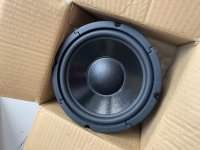
I run a music studio (with my partner at work), and I build audio studios for a living. My listening rooms rooms are very highly damped - known as 'non environment' or 'hemi-anechoic' rooms. There is little to no 'room gain'. An 8" studio monitor just about manages to do the job, but for any serious visceral impact/scale, a large format pair of speakers is a must. There are no large format monitors available at under $15K or so, and the expense increases significantly by the time it gets here to India.

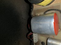
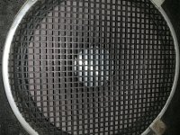
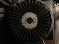
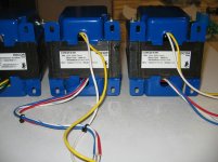
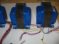
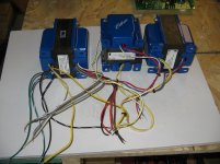
So, I have been building large format speakers for some of my rooms - I have built 'Econowaves', 'Pi Speakers' and 'SEOS' based speakers from designs proven in the DIY world. For some of these designs, I have bought drivers and parts from abroad (Including an AE TD15H which my cat just destroyed and a pair of Exodus/Anarchy subs, the servicing of which is going to be a PITA).
Servicing and spares when I buy gear from abroad is a nightmare. And ant any time, your consignment may be held up at customs indefinitely, and you might be charged an arbitrary fee to get your stuff cleared.

As it happens, there are a number of 'Pro Audio' speaker companies represented in India. Eminence, B&C and Beyma I have used a few times before, I believe Faital Pro, BMS and a few others are also here... strangely, their pricing is competitive with USA/European pricing - possibly because of reduced customs levies on "spare parts", when imported by the distributors here who have an organized system of dealing in larger quantities. These guys have warranties, spares, repair centres etc., so working with what is available locally is a much more viable option.

Even though I am proud of the speakers I've built as they are working hard everyday in a few studios, I know that they all have serious flaws, and I don't have the bandwidth or wherewithal to really "design" a pair of serious speakers.

I have been working on a few ideas (driver/electronics combinations) and I am putting together a document detailing what I have found so far, what I am looking for and what I am willing to offer.

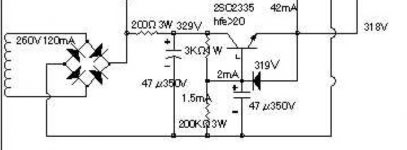
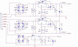
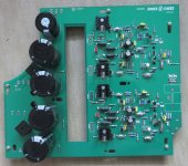
The design will be of a tri-amp'd DSP driven system capable of putting out at least 110 dB continuous, at a cost of <$3K in parts (including electronics), per pair.

Full disclosure - I wrote to Troels G who politely declined. I wanted to approach John of Zaph Audio, but I didn't, because he has made it publicly clear that he doesn't want to be contacted. I want to reach out to "GM" (who always makes valuable contributions, my ideal collaborator!) who, it seems, also does not want to be contacted... so I have to go public like this!

Who will consider joining me in my endeavour? Either PM me or make me a recommendation for someone who might be interested... It should be obvious that the money and scale involved will not be big, but I believe my offer will be transparent and fair... so for somebody who is already an enthusiast and can spare some time, this would be a good fit...

Sincerely,
audiothings.

Kenwood Ka-1000

Looking for transistor subs for a couple of transistors in the pre-driver part of the circuit, Q31/33 the originals are 2sa564a, this is a pnp to-92, 150mhz part with max -7 Vebo, Hfe 180-360

A close subs i've found was ksa1381 a to-126 part no big deal with that but the Vebo is only -5 volts max, would I ever see over -5 volts here?

Or the Ksa1220A, differences larger value cob at 26pf, original 3.5pf and again Vebo at -5

Any other subs I should be looking at

Attachments

  • ka1000.PNG
    ka1000.PNG
    108 KB · Views: 254

Question - Aftermarket System on 2003 Toyota Sequoia

Question - Aftermarket System on 2003 Toyota Sequoia and need the wire diagram from head unit. The Toyota cam with:

Audio system radio JBL AM/FM/RDS Radio 6 CD DISC Changer & Tape Player. I think it has 2 JBL amps, one by the radio and one below the center console. I can post the wire loom is needed.
MODEL # 86120-0C120
REF. # CQ-ET1262X

The picture shows the back of the radio the larger plug uses the most wires while the far left plug only uses 3 wires.

Any help would be appreciated Thanks,

Attachments

  • IMG_2898[188].jpg
    IMG_2898[188].jpg
    628.4 KB · Views: 512

1,000uF Capacitor

I saw the schematics of B&W 801 and 802. They had a 1,000uF capacitor in woofer’s section which is connected in series closet to the woofers. Is this capacitor be a high-pass filter? Not sure whether it’s called passive subsonic filter or not. What is the responsibility of it? Does it used to reduce the bass boom? Can any speakers be simply added the 1,000uF capacitor in series to their woofers for the purpose of bass improvement as did in B&W?

Vintage CD Player woes .. need to pick the brains of the techies in the house.

Ok I need to pick the brains of the technicians in this group. Maybe someone will have a clue, cause I sure don't! lol ... I have a CD player (B&O CDX) that once turned on, has to sit for 5 - 10 mins before it can be played. The strange thing, is how it tells you when its ready to be played. I press power, don't touch anything else and just let it sit .. 5 or so mins later, it will emit a loud static out of the speakers, which will then slowly taper off over about a minute. After this, I can play the CD no problem (with a bit of static here and there). If I try to play a CD before that, it will just sound distorted until that same 5 or so minutes passes, then the sound clears. Anyone have a clue?

Things that have recently been done to this player, so can be ruled out as the cause are:

-Griplets fixed (common philips CD 104 issues)
-solder touch ups
-RCA cables replaced
-lens cleaned
-voltage regulators replaced
-reed switches replaced
-OP-AMPs replaced with TI LME49720
-electrolytic caps replaced on pre.ampl. & Laser PCB
-electrolytic caps replaced on motor board - PCB disc motor stop
-electrolytic caps replaced on decoder board
-electrolytic caps replaced on power supply board
-electrolytic caps replaced on servo board

Total Newbie

Good afternoon Guys,
As an electronics engineer of some 40 years steeped in transistors and microprocessors I thought I'd have a foray into the world of tube audio which I last dabbled in during the 70's.
Thought processes and lots and lots of reading and videos led me to decide on a first simple Single ended stereo low power amplifier based on 12AU7 and EL84 combination, being me, I didn't want to just copy an existing design, but build one from the bottom up, using a mixture of calculations and trial and errror.
Therefore I have knocked up a prototype single channel amp so I can fiddle/adjust before making something that really looks good, using own design turret board etc.
Cutting to the chase, if anyone could (constructively) criticize comment on the diagram I have attached I'd be very grateful. The amp sounds quite good really, simple 'scope readings seem to indicate that it has a reasonably flat frequency response although I think it lacks treble and the bass sounds a bit wooly/muffled.

Hopefully as this grows I can use the other half of the 12AU7 as a cathode follower to drive a 3 channel tone stack - but that's for later on !

Many Thanks from a newbie needing guidance, and thanks for allowing me to join the forum.

Steve

Attachments

  • SE-SRH0001.jpg
    SE-SRH0001.jpg
    153 KB · Views: 263

First time designing crossover, comments needed

Hi guys, I am new to the forum and also my first time designing a crossover for a 2 way speaker. Done it using XSim and attached are the frequency responds and Impedance curve. Do the curves look alright or is there something needs to be corrected. Look forward to your comments.

Attachments

  • 2-way Dayton RS180P-8 + Peerless XT25BG60-FR.jpg
    2-way Dayton RS180P-8 + Peerless XT25BG60-FR.jpg
    135.9 KB · Views: 174
  • 2-way Dayton RS180P-8 + Peerless XT25BG60-Imp.jpg
    2-way Dayton RS180P-8 + Peerless XT25BG60-Imp.jpg
    134.3 KB · Views: 180

So, up to what frequency are drivers REALLY omnidirectional?

I have a dream of making two custom consoles/cabinets with matching speakers, and the speakers looking different by having only a horn visible. Ideally this would mean having woofer(s) on the back* or 2nd best the sides, some of which would be slot loaded (Left - cabinet - Center - cabinet - Right with at most a couple inches in between. TV sitting on top.

This raises the question:Up to what frequency are woofers really pretty omnidirectional?
(0) Can anyone point to DATA of woofers measured at 90 degrees or even better behind the cabinet?
(1) Hmm, I can calculate theoretically that at 90 degrees from forwards, if we say 90 degree phase shift for -3 dB cancellation IIRC, that is 1/4 wavelength. So let's pretend a 12" woofer is actually a 12" piston. That means 1/4 wave = 1 foot, so wavelength λ = 4 feet.
v = f * λ
1100 ft/s = f * 4
f = 1100/4 = 275 Hz.
Does that seem correct?
(2) At higher frequencies, effective piston area can narrow. Is this a factor at frequencies before the speaker becomes directional? I'm thinking not...
(3) If we put say two 6" next to each other, I'd expect the same result as above, again ignoring that the piston diameter is not really the same as the woofer size. BUT what if we put two 6" next to each other facing the wall? And what if, further, you put a physical divider between the speaker and the wall? On the one hand, it seems that should keep the wave from one 6" from interfering with the one next to it, meaning each 6" only cancels its own wave. On the other hand, that seems like a free lunch. 😕


*https://www.diyaudio.com/forums/multi-way/357957-backwards-facing-loudspeaker-project.html
Probably dreaming the impossible dream, I'm rather doubting I can get a horn to go low enough without (a) becoming too wide for the space available and (b) able to cover up to the top treble even using EQ.

TDA1541A Diy Pcb - "Distinction-1541 v2"

Lovers of the TDA1541A -

"Distinction-1541 V1" Was a success thanks to the combined knowledge of the DIY community.

I start this thread for a place for myself to share what i'm working on with the TDA1541A, however unprofessional it may seem. I admit i'm certainly no expert. I just want to share my experiences with like minded people.

A new direction for the project has obviously been led by myself; wanting more from the TDA1541A - Especially after hearing just what V1 was capable of.

Design goals for v2:
-Simplicity
-Cost effective vs performance
-Attention to detail of Pcb design topology
-The use of the latest passive technology in SMD formats

The output stage for the TDA1541A is normally a personal choice for particular reasons so this part will be left out. I continue to use the "CEN Passive IV"

Attached to this post you will find a few pictures of the progress v2 has currently undergone. These pictures by no means represents what the finished product may or may not resemble - they simply show what i'm working on at the moment to attain the ultimate goal of the final product.

Please note that there are design compromises in every PCB design and this one is no different - all i'm doing is selecting the parts to the system I feel to be important based on simulation, practical testing and of course, most importantly - listening.

Ryan.


Distinction-1541 v2 - GB interest list. - diyAudio

Attachments

  • atten progress.jpg
    atten progress.jpg
    424.9 KB · Views: 4,602
  • v2 progress.jpg
    v2 progress.jpg
    907.2 KB · Views: 4,445
  • Different values1.jpg
    Different values1.jpg
    483.8 KB · Views: 4,228

FS: 4x120W Power Amp BA-4120CP, selectable output impedance

In working condition. I have replaced all of the SMD capacitors on the ceramic hybrid modules for Polymer types, so now they're better than new 😉.

I'm asking for EUR 100,-, which is about what all those caps cost, excluding shipping. I'm located in GERMANY, where shipping will be EUR 15,-. Please ask me for the shipping cost to your country, should you be interested.

Attachments

  • 40225788.pdf
    40225788.pdf
    288.7 KB · Views: 65
  • image001.jpg
    image001.jpg
    279.3 KB · Views: 137
  • image002.jpg
    image002.jpg
    266.5 KB · Views: 137
  • image003.jpg
    image003.jpg
    292.9 KB · Views: 134
  • image004.jpg
    image004.jpg
    421.7 KB · Views: 141
  • image005.jpg
    image005.jpg
    282.7 KB · Views: 126
  • image006.jpg
    image006.jpg
    437.7 KB · Views: 87
  • image007.jpg
    image007.jpg
    387.7 KB · Views: 88

FS: 2x Class-D PA Power Amplifier 250W Simax LV 250

I have two of these, one is still working, the other one does not start up. They were both working until I took them out of service, so probably only the supply capacitors are flat. If you remove the 100V output transformer, you have two beefy mono blocks for 4/8Ohm speakers. Even if you don't have any use for them as-is, there're lots of nice parts to scrap them for. The parts and build quality is top notch, as they're designed to run 24/7.

I'm asking for EUR 50,- each (100,- for both), excluding shipping. I'm located in GERMANY, where shipping will be EUR 10,- to 15,- each. Please ask me for the shipping cost to your country, should you be interested.

Attachments

  • image001.jpg
    image001.jpg
    239.6 KB · Views: 142
  • image002.jpg
    image002.jpg
    283.4 KB · Views: 157
  • image003.jpg
    image003.jpg
    353 KB · Views: 150
  • image004.jpg
    image004.jpg
    393.2 KB · Views: 162
  • image005.jpg
    image005.jpg
    465.9 KB · Views: 143
  • image006.jpg
    image006.jpg
    439.4 KB · Views: 94
  • image007.jpg
    image007.jpg
    485.5 KB · Views: 83
  • image008.jpg
    image008.jpg
    425.1 KB · Views: 86

Marantz PM40SE Left Channel Blown

Hi All


I have a Marantz PM40SE repair as a project.


Tested with a DBT. The relay does not click on obviously!.
Right channel bias reads 5mv but left channel reads 35volts (approx).


Q763 - 2SA1265N and Q751- 2SD1508 have blown on the left.


Q761- 2SC3182N on the left is ok


General resistors look ok.


Q759 on left was getting hot even with DBT but tested OK.


Please can you give me modern equivalents for Q763 and Q761 (change in pairs if needed) and Q751. Any other advice would be appreciated.


Thanks

The perfect small class d for me.

I thought i had the perfect small class d amp, the latest version of a Fosi audio TDA7498e mini power amplifier

It doesn't have a ton of power but it's actually okay for my 8 ohm 85db rated speakers after i haven gotten use to the sound and power

It doesn't have bluetooth and tone controls (don't need it)

It's has no pop sound when turning the amp on and off and theres no channel imbalance.

What it actually has is some static noise when i adjust the volume, not always and not the entire rang from low to the max range, still from time to time noticeable when there is music playing (when i touch the case when adjusting the volume there isn't any noise). Which i just found out after i bought a 24v 10a power supply as the most powerful power supply suggested by fosi amp for the TDA7498E amp they make

Fosi audio reply (it's not by me accepted as a 100% acceptable answer, should be possible to make the amp without the static noise).

It's normal that when you turn the volume up or down, there is some static noise from the speakers, but once you stop spinning, the noise disappears.

It's the ground issue because the volume knob is made of aluminum


It's tricking my ocd, my cheap Tube T1 tube buffer don't suffer from static noise adjusting the volume and im not even tricked by the fact that the fosi amp isn't black and all of my other unit's are but i have problem with the noise that can be noticeable when i adjust the volume.

Shure i can just use the tube amp to adjust the volume, i used the amp without the tube buffer and stil liked the sound and would have like to use it without the tube buffer for a longer period


The perfect mini class d power amplifier for my needs must have more more than 2x20 in 8ohm with less or max 1% thd

No pop noise when i turn the amp on and off

No noise when i adjust the volume

No channel imbalance

under 100 euros with shipping

Does such an amp exist ?

I must admit i like the sound from my fosi amp, i just don't like the noise i sometimes percive when i adjust the volume :sad:

Phono pre amp build recommendations

I have built a poindexters 6v6 push / pull amp (4 W output) and now want to build a tube phono pre amp for my music Hall turntable with a Grado Green cartridge. I would like a simple build (not necessarily a kit - more $$) with schematic that a newbie can follow. Does anyone have experience with the Steve Graham Design published in a 6 part series in Wall of Sound last year (2019). Any direction / help would be greatly appreciated.
Thanks so much

Don't listen to records on FM!

I don’t mean FM radio, I mean FM as in Frequency Modulation Distortion (FMD, or pitch instability). FM occurs as a result of the stylus tip scrubbing along the groove during tonearm mass/compliance resonance or transient events. The amount of scrubbing depends on the amplitude of the resonance or transient event but I want to show that it also depends on arm geometry, and that there are arm geometries that can minimize it. I’ll present graphics, computer animations, and video sound clips to demonstrate that arm geometry can affect apparent turntable pitch stability which, in turn, can degrade the measured wow & flutter figure of an otherwise excellent turntable. This is not another alignment thread.

I’m starting this new thread as a spinoff or extension of topics discussed in the diyaudio “Turntable speed stability” thread:
https://www.diyaudio.com/forums/analogue-source/309349-turntable-speed-stabilty.html
…and there are some roots in the “Test LP group buy” thread:
https://www.diyaudio.com/forums/analogue-source/313335-test-lp-buy.html
Much has already been written and discussed about the AM effects of resonance and ways of dealing with it, including various implementations of tonearm damping and commercial/diy low-pass electronic filters. However, the FM effects of stylus scrubbing cannot be removed electronically downstream by low-pass filtering.

If there’s a mass/compliance resonance event, the stylus scrubs. If the stylus scrubs, there is FM.

Any arm motion that causes cantilever deflection will also result in stylus scrubbing fore & aft along the groove. Stylus scrubbing changes the relative groove velocity, which causes a pitch variation or speed instability that can sometimes be audible, depending on program material and individual listener pitch sensitivity. The mitigation of scrubbing arising from horizontal versus vertical displacements involves different arm design tactics. Here is a familiar graphic from Shure tech notes which shows how horizontal mode scrubbing is affected by the offset angle of a typical pivoted arm:

attachment.php


[01] Shure Figure 2 Simplified Lateral Scrubbing

Shure’s graphic shows a simplified relationship between horizontal motion and scrubbing along the groove and a simple formula that describes it. Notice that the scrubbing motion is asymmetrical WRT headshell/cantilever displacement. For a symmetrical sideways displacement of the headshell, the stylus scrubs farther aft than it does forward. More on that later. The motion of the stylus point in the groove can be calculated if the groove radius, the stylus cantilever length, the arm pivot to spindle distance, and the distance from the arm pivot to the cantilever pivot/suspension is modeled as a four-bar mechanical linkage. This model works for all types of arms, whether S shape or J shape with an offset bend in the arm tube, or straight type with an offset angle at the headshell. It also works for most servo linear arms, which are generally just motorized pivoted arms with no offset angle. Air bearing and passive/mechanical linears can also be analyzed but within a certain range of assumptions.


attachment.php


[02] Four-Bar Linkage Model

It’s easy to demonstrate the scrubbing motion yourself by making a crude working mockup of this four-bar linkage system with a plastic coffee stirrer. Cut a flexible joint notch in the stirrer at about ¼ of the length. Bend it 90 degrees at the notch. Anchor the long end of the stirrer to the turntable spindle (this becomes the groove radius ‘link 1’), then slip the short end over the cartridge stylus (this becomes the stylus cantilever ‘link 2’, and you’ll want to use a junk cartridge for this). The line from the arm pivot to the spindle becomes ‘link 3’, and the line from the arm pivot to the stylus cantilever pivot (aka cantilever suspension) becomes ‘link 4’. Note: ‘link 4’ as defined is not the same as the arm’s “effective length”! For this mockup demo I used a cheap ceramic cartridge and then rocked the tonearm sideways left/right to see what happens:


[03] Tonearm/Stylus Scrubbing

More on the way…

Ray K

Attachments

  • [02] Four-Bar Linkage Model 800x605.jpg
    [02] Four-Bar Linkage Model 800x605.jpg
    253.5 KB · Views: 1,385
  • [01] Shure Fig 2 Horz Scrub 400x445.gif
    [01] Shure Fig 2 Horz Scrub 400x445.gif
    24.1 KB · Views: 1,499

FS: Classic subwoofer drivers

Tang Band W8Q-1071F 8x12 woofers

tb_w8q-1071f_1.jpg


I bought these several years ago with the idea I was going to make a speaker inspired by the famous TDL Reference. It turned out to be one of “those” projects, so these speakers have never been mounted. It turns out these are the holy grail in a transmission line:

https://tdldiy.files.wordpress.com/2012/08/tangband-mild-stuffing-graph.png


All specs from manufacturer data sheets:

DCR IMPEDANCE: 3.2 Ω
SENSITIVITY 1W/1m: 88 dB
FREE AIR RESONANCE:27 Hz
AIR GAP HEIGHT:8 mm
RATED POWER INPUT:250 W
FORCE FACTOR, BL:14.57 TM
MOVING MASS:134.66 g
X-max:12 mm
Vas:70.42 Litr
Qts:0.34
Qms:4.6
Qes:0.36

Full specs: https://tdldiy.files.wordpress.com/2020/08/tang-band-w8q-1071f.pdf

$60 each, $100/pr or $150 for all 4 plus shipping & PayPal

Foster NPT-11-083 10” Woofer (from NHT VT3)

npt-11-083_1.jpg


These were from the famous NHT driver closeouts some years back. These have never been used, though they have been sitting up on the shelves for quite some time. I have 3 of these left. These are some of the best sealed cabinet designs around. From the high DCR, it’s clear it was meant to be used in pairs. Or perhaps all 3 in a balanced force arrangement?

DCR IMPEDANCE: 9.53 Ω
SENSITIVITY 1W/1m: 84.48 dB
FREE AIR RESONANCE:16.6 Hz
VOICE COIL DIAMETER:50 mm
FORCE FACTOR, BL:15.05 TM
MOVING MASS:134.66 g
X-max:13 mm
Vas:174.27 Ltr
Qts:0.390
Qms:4.201
Qes:0.430

Full specs: https://tdldiy.files.wordpress.com/2020/08/nht_drivers-2.xls

$30 each, $75 for all 3 plus shipping & PayPal

Happy listening,
Frank

cornwall/E-V aristocrat/statement MONO corner project

Hi everyone,

I decided to build my own speaker (first build). I said 'speaker' and not 'speakers', as this is intended to be a mono-speaker project. I have a nice mono tube amp to feed this speaker. But I need some advice...

The idea is the following:
In my living room, I have 1 corner available to put a speaker. As our living room, dining room and kitchen are 1 big space, this one speaker is intended to fill the whole room as well as to play background music in mono.

I have the plans to build the 'statement' speaker (see Statement ), but with slightly other dimensions, as it looks are not really WAF-proof. The statement is a 2-way speaker with a horn for the highs. Crossover at 2000Hz. It's design is based upon a cornwall, although it has less height than a cornwall and a down-firing bass port.

Anyway, it seems that corner placement is a big issue, hence my post here.

Following are my options:
1/ build the statement within a Cornwall chassis (or 'Klonwall'), which is a design I like. Since the statement is based upon a cornwall, this shouldn't be too much of a problem i think? The statement is 80cm in height (vs 90cm cornwall) and having its bass port underneeth (vs in front cornwall). Corner placement shouldn't be too much of a problem since CORNwalls are supposed to be place-able in corners.
2/ Build the statement within an Electro-Voice Aristocrat (upscaled for 15" woofer, roughly same dimensions as a cornwall) chassis. The aristocrat was designed for corner placement and is a klipsch-designed (although there is some debate) corner horn. See: retro vintage modern hi-fi: Aristocrat
3/ build the statement, but not in rectangular shape but in 'aristocrat'-shape. this means cutting corners in the back side of the chassis, but keeping internal volume the same by making the speaker larger. The internals of this speaker are not the Aristocrat horn, but stil a BR with down (or front?) firing port.
4/ Build the statement as is. Since we are talking only one speaker here, corner placement issues with stereo speakers are not in play (according to a philips booklet of 1958, mono speakers are best placed in corners, as side walls reflections help fill the room). Or is this not correct, and is a speaker with down-firing port not suited for corner placement?

any opinions and advice is more than welcome!

ps: Plans of the 'Klonwall' (in dutch...), see: Een Klipsch Cornwall wordt een stoere Klonwall zelfbouw luidspreker

Capacitor aging in a zobel network impedance correction network

Hello,

So after 15 to20 years, the capacitance of a bipolar lytic is agging enough in the speaker filter for people wanting to change it.

If I know ears adapts themselves little by little and don't notice that agging years after years, it's clear after a filter refuurbishing with brandnew caps the speaker was not the same.

I was asking how is translated the sonic experience when a cap is getting too much old and see its esr and capacitance changing in an impedance zobel network correction circuit that flat impedance resonance if I understand correctly.

Let say the impedance curve is low enough, for illustration 4 ohms to 2 ohms. Let say the in the RC after agging a 100 uF cap is measured after 2 or 3 decades at 130 uF - knowing often the capacitance precsion fo a standard bipolar was 20% - What is the result in the impedance network of that capacitance rise and the result when listen to it with the speaker please ?

I surmise it is lowering perhaps the impedanceresonance below the average flat impedance curve and can be a danger for the amp by a too much low Z there, especially in the bass area ? (let me think a bout the treble in ESL speakers when dropping below 2 ohms in the high end of the trebles-

Less bass are perceveid ? I also surmise the esr of the cap vastly increased as the capacitance of a lytic cap when agging is first lowering then increasing above its initial value... so at the end increase the Z of the zobel network as well ! Does it age faster than serie caps with the driver in a speaker filter ?

Sorry, several questions in one,

many thanks for any input about that,
cheers.

Rudi_Rozek ACA PCB boards with 65% of Parts to Build

I have built 9 of Rudi's upgraded torroidal Amp Camp Amps that feature TungstenAudio's part modifications and JasonKeutemann's CapMX Power Supply and these amps are fantastic!

I over ordered on the boards and have no use for this last pair and the spare parts I still have left to build another pair. You will receive:

- 2 of Rudi's PCB boards
- 4 10,000uf filter caps
- 2 1000uf Organic Polymer caps (Tungstenaudio Recommendation)
- 2 100uf Organic Polymer Caps (Tungstenaudio Recommendation)
- 2 10uf Panasonic caps
- 2 5K trimmer Pots
- 2 50k trimmer Pots
- 4 IRFP140 Mosfets
- 2 KBU8b Diode Brides
- 2 IRFP9240 regulators
- 4 2.2uf Wima Caps for Power Supply
- 2 Toshiba 2sk170 JFETS
- 2 4700uf 35V Nichicon Gold Caps (Tungstenaudio Recommendation)
- 4 PCB Mount Terminals
- 4 Spade Connectors
- 4 KSC 1845 for Power supply (need 2 more)
- 4 MPC71 Metal Film .47 Resistors (Fukushima 5 Watt)
- 4 MPC71 Metal Film .22 Resistors (Fukushima 5 Watt)
- 4 MPC71 Metal Film .56 Resistors (Fukushima 5 Watt)
- 2 Nichicon 1000uf Caps
- 1 Bridging switch for mono
- 1 XLR input for mono
- 1 IEC connector
- 1 Fuse Holder
- 4 blue leds
- 2 10pf Mica caps (Tungstenaudio Recommendation)
- 2 100n ceramic caps (for Power Supply)

All of these are parts that Rudi recommended I used in my amps with great results. You only need to buy the resistors and 2 more KSC1845. I recommend Vishay/Dale RN55 1/8 watt or Beyschlag .6Watt resistors to fit this board as the spacing is pretty tight. I successfully used some RN60/65 1/8 watt but they take up a bit more space. I can include all resistors I used in my builds for just $25 more.

As for Power Supply, I used the Antek AS 2022 and 2222 but would also recommend the 2422 as these amps benefit from good power supply and higher voltage secondaries.

Asking me any questions about my builds. Pictures of my example builds are listed using 5in.Hx9in. Lx3in.W (fin size). I have heard the mini dissipante 3u works great.

Asking $150 SHIPPED in the CONUS ONLY please. $175 and I will include all the resistors you need.

Attachments

  • IMG_0865.jpg
    IMG_0865.jpg
    1,011.8 KB · Views: 207
  • JTGU6920.jpg
    JTGU6920.jpg
    1,009.1 KB · Views: 207
  • RBZP8650.JPG
    RBZP8650.JPG
    716.8 KB · Views: 203
  • IMG_1002.jpg
    IMG_1002.jpg
    1 MB · Views: 198
  • IMG_1001.jpg
    IMG_1001.jpg
    1 MB · Views: 198

I want to build my first speakers. What design would suit my very weird living room?

So, I want to build my first set of speakers. It seems like something well within my skills, a fun project and a way to save some money. However, I am not sure which design would fit in my strange apartment. It would be great if you could recommend me a proven design which fits here.
AsSgyTT.jpg

I am looking for a bookshelf speaker design which fits in the bookshelf on the left. I’ll replace the bookshelf but the new one will also be 35cm from the edge to the wall. I have a ceiling height of 4m but the room is just 3m wide. I don’t need very loud speakers, only light listening and for the TV audio. It would be great if I could also listen from upstairs without it sounding terrible. I’ll buy a Topping MX3 as the amp.

From what I read the distance to the wall would probably be too small for a back vented design. Would something with a passive radiator on the sides be a good choice here? I like the look of those. Also, a lot of DYI designs are in imperial measures. Can I just use thicker MDF as long as I keep the inside dimensions the same? If the design is a bit bass anaemic it would be fine as I’ll probably add a subwoofer later on.

Texas Instruments TPA3255EVM Evaluation Modules and Mean Well SMPS

Clearing out extra audio electronics in storage. I have the following for sale.

  1. Texas Instruments TPA3255EVM Class D amplifier modules, lightly used, 2 units, original packaging, $45 USD each
  2. Mean Well LRS-350-48 SMPS, lightly used, 1 unit, original packaging, $15 USD
A31DB0B4-95CC-46C4-9622-4C00FAFA7888.jpeg 8F819B77-A705-407D-94C0-D83966BD68AD.jpeg

  • $95 USD for everything.
  • Must add shipping within continental US (not included).
  • Prefer to ship via USPS Priority Mail or FedEx for tracking.
  • Only PayPal payment accepted. Will waive PayPal fee.

Can low jitter be achieved with STM32 microcontroller

Hello,

I consider starting a project tha would basically use receive music from USB, apply DSP and Crossover management and output I2S or SPDIF fo feed 4 x Full Digital Amplifiers channels (here 2x FX-Audio D802 with SPDIF), using a STM32F7 Nucleo board.

The chips have a DSP instruction set. Those boards can address in a quite rich way multiple I2S and SPDIF, in a synchronized way. They can use a dedicated oscillator for the audio part and have dedicated audio PLL. Last, they are cheap. It seems to me a good basis for a low jitter system.

But, I'm a beginner here, I lack a lot of knowledge, and for those topics the devil is in the details...

Objective is to be at least better than what would be achieved on a Raspberry Pi on the I2S output (should not be too difficult), and ideally achieving 95% of the performance of the "reclocking" boards considered here (I know how the last 5% can be hard to achieve in many cases).

Any comment, warning and advice is warmly welcomed.

JMF

Parallel vs Series Tuned 6th order bandpass boxes

So I was discussing 6th order bandpass boxes with someone on another forum and the question came up, just what is the difference in performance between series tuned and parallel tuned boxes?

If you had two boxes with the same chamber volumes and tunings but one was parallel tuned and one was series tuned would they sound any different?

My understanding is that they would sound the same since once you get below the front chamber's tuning frequency the port unloads and then begins to function as part of the rear chamber's port once you get closer to the rear chamber's tuning. Or am I completely wrong and don't know what I'm talking about? That's happened before. 🙂

Any input will be greatly appreciated!!!

Paraflex for dummies...and things very SIMilar

Paraflex, Transflex, rear vented qw pipes.... ROAR, compound horn, offset port QW pipes and horn shapes....

Bring it! And bring your buddies too.

These things are too much fun. Even if quite complex and even a PITA to try and design your own, the fun is undeniable, and if you get it just right, and it’s your type of sound, wow can it be rewarding!

Maybe this can be ‘that thread’? Diy supercalifragilistic -pipe/horn- alidociius?

No names. But if you are affiliated with any of these things, let me say from the bottom, the nooks and crannies of my heart, the very most sincere thank you, and respectful appreciation for what you have shown me or made available to see:wave: for all.

My hopes here are to try and make Horn Response allow me (and anyone)to accurately portrait these types of ideas . Not per the name or it’s creators vision, I cannot claim to do this perfectly or am. That is respected. But those are key examples of very functional versions and similar in many ways, yet Entirely different too..

Adding pics below...

Box of entry-level speaker building components

Hi

I've got a lot of speaker-building components purchased years ago for 2 projects that were never started - all were sourced from Parts Express I think, all import duty paid. All of the following are included and brand new:

Project 1 - intended for a Kilner jar Bluetooth speaker project

1x BOSS B25N GROUND LOOP ISOLATOR AND NOISE FILTER
1x DAYTON AUDIO RS75-4 3" REFERENCE FULL-RANGE DRIVER 4 OHM
1x DAYTON AUDIO DTA-2 CLASS T DIGITAL AUDIO AMPLIFIER MODULE
1x BLUETOOTH V4.0 AUDIO RECEIVER BOARD APTX +EDR 12 VDC


Project 2: intended for a bookshelf speaker set project:

2x Dayton Audio XO2W-2K 2-Way Crossover 2,000 Hz
2x Port Tube 2" ID Adjustable
1x #6 x 3/4" Deep Thread Pan Head Screws Black 100 Pcs.
2x Dayton Audio DC160S-8 6-1/2" Classic Shielded Woofer
2x Dayton DC28FS-8 1-1/8" Silk Dome Shielded Tweeter
1x Speaker Gasketing Tape 1/8" x 3/8" x 50 ft. Roll
1x 14 AWG Royal Cable High-Strand OFC Speaker Wire 50 ft. Roll

Also 2x BK Electronics PP-50 amplifier panels

In total, including shipping and import costs, it's about £500 of brand new components. To get rid of it and a quick sale, I'm looking for £200. I can get a quote to post it in the UK, but I live in London and it would be better if collected.

Attachments

  • IMG_9236.jpg
    IMG_9236.jpg
    930.8 KB · Views: 129
  • IMG_9237.jpg
    IMG_9237.jpg
    975.7 KB · Views: 126
  • IMG_9238.jpg
    IMG_9238.jpg
    514.9 KB · Views: 122
  • IMG_9239.jpg
    IMG_9239.jpg
    978.5 KB · Views: 124
  • IMG_9240.jpg
    IMG_9240.jpg
    916.9 KB · Views: 131
  • IMG_9241.jpg
    IMG_9241.jpg
    975.6 KB · Views: 68
  • IMG_9242.jpg
    IMG_9242.jpg
    701.6 KB · Views: 59
  • IMG_9471.jpg
    IMG_9471.jpg
    993.1 KB · Views: 90

FS: JC2 Clone Kit,

I’m offering a DIY Symmetric Complementary J-FET preamplifier based on JC-2! A pair of 2SJ103BL and 2SK246BL are used in the differential input stage, a 2N2209A and 2N2219A each are used for the output stage. The relays come from SDS / Nais Panasonic DS2E-SL2-DC5V. The diagrams will be send by email. PCB dimension : 113mm x 93mm thickness : 1.6mm. Operating voltage AC input between 2 x 16V to 2 x 18Vac. Asking 60 Euro + 4% PayPal + Shipping inside the EU is prefered. Ship from Germany. Send me a PM when you interested or you have questions.

Attachments

  • JC2.jpg
    JC2.jpg
    167 KB · Views: 492
  • JC2 (1).jpg
    JC2 (1).jpg
    527.6 KB · Views: 364
  • JC2 (3).jpg
    JC2 (3).jpg
    416.9 KB · Views: 298
  • JC2 (4).jpg
    JC2 (4).jpg
    390.9 KB · Views: 271
  • JC2 (9).jpg
    JC2 (9).jpg
    517.2 KB · Views: 271
  • JC2 (12).jpg
    JC2 (12).jpg
    384.6 KB · Views: 131
  • JC2 (11).jpg
    JC2 (11).jpg
    387.3 KB · Views: 137
  • JC2 (13).jpg
    JC2 (13).jpg
    395.7 KB · Views: 157
  • 2.jpg
    2.jpg
    176.9 KB · Views: 187
  • 3.jpg
    3.jpg
    113.7 KB · Views: 221

Merlin 3B+ Speaker Refurb

This is a pair of Merlin 3B+ speakers made in Rochester, NY circa 1990. These were given to me by a former co-worker, whose wife was tired of looking at them, and thought they were too big. I gladly helped them solve the problem.

The original foam covering had completely disintegrated, the wood finish had some minor damage, one of the woofers had come disconnected, and the midrange and tweeter pots needed some cleanup. The bottoms are loaded with sand, and they weigh over 100# each. These were a pretty serious pair of high end speakers that retailed for close to $1000/pr, and still sound pretty amazing even by today’s standards. I owned a pair of the larger Merlin 4s years ago. I cured the performance ills, sanded and re-oiled the oak caps, and re-wrapped the tubes with 1/4” 30 ppi filter foam. ~ $45 of materials, and they’re back to looking like new.

At some point I may eventually pass these on to one my kids who would appreciate them, but for now the Merlins reside in my basement system, and sound great driven by the small Stromberg Carlson ASR-120 tube amp I refurbed last spring.


000_3918.JPG 000_3921.JPG 000_3928.JPG 000_3939.JPG

000_3940.JPG 000_3941.JPG 000_3942.JPG

TPA3251 2Ch Amplifier Board DIY Design (Compact size/Amazing Performance)

Hi Guys,

Glad to share your guys with my customized DIY design - TPA3251 Amplifier Board for DIY Application.
this AMP and SMPS were released to my friends a few months ago and also have been used into their project successfully.

As your guys already know,the TPA32xx series chip have a lots of improvements,it features an advanced integrated feedback design and proprietary high-speed gate driver error correction to allows ultra low distortion. it attract many DIYer to start his own design to enjoy the excellent performance and also more and more companies have involved this chip into their product.

Key Features of My Design
  • Enhanced design with very low output noise (62uV/A-weighted) and lower THD+N (0.0015%/20W/4ohm)
  • Fully differential layout design for better noise cancellation
  • Smaller and Compact size(105mm*90mm*36.5mm – L*W*H)
  • Additional power ON/OFF reset circuit for Pop noise suppression
  • BTL configuration only for best audio performance
  • Single supply voltage range 24V~36 V(UVP:24V)

Full Project Detail:TPA3251 2ch PurePath™ Ultra-HD Class D Audio Amplifier

Performance Measurements Detail:
Audio Performance Measurements_EAUMT-0140-2-A
Audio Performance Measurements_TPA3251D2EVM
Audio Performance Measurements_TPA3251D2EVM_vs_EAUMT-0140-2-A

Attachments

  • EAUMT-0140-2-A_45°.jpg
    EAUMT-0140-2-A_45°.jpg
    653.2 KB · Views: 4,183
  • EAUMT-0140-2-A_Front.jpg
    EAUMT-0140-2-A_Front.jpg
    661.6 KB · Views: 4,084
  • EAUMT-0140-2-A_Back.jpg
    EAUMT-0140-2-A_Back.jpg
    593.5 KB · Views: 3,971
  • THD+N_vs_output power.jpg
    THD+N_vs_output power.jpg
    451.3 KB · Views: 3,917

[WTB] CBT24K speaker kit - prefer unbuilt

Looking for a pair of the Don Keele CBT24K speaker kit that used to be offered by parts express. It went NLA a few months before I was going to buy a pair. Interested in an unbuilt set, but will consider assembled if the price is right. I figure there have to be a few sets in garages out there that just never got built.

Please let me know what you have. Thanks!

Got my first Karlson! Europe made K15 clone

I always wanted to try a Karlson, what it sounds like. But it was down low on my project list. Therefore I got excited when I saw one for sale, as they seem to be rare in Europe and almost unobtainium in CZ. For ca 70 Eur I got this German made K15 clone. The speaker inside is DAS BI-30 15" speaker, it must be really old. The box itself looks very well made from plywood. There is some kind of crossover inside, throught the hole I could see two caps and one coil.

It is supposed to be fully functional, I need to replace the XLR connectors by Speakons and do some listening and measurements.

Attachments

  • C4BFA638-91B1-43C0-83FD-E30FF83AA9F6.jpg
    C4BFA638-91B1-43C0-83FD-E30FF83AA9F6.jpg
    1 MB · Views: 778
  • 2338EAC9-AE99-4580-AF3A-88A0EFCCB319.jpg
    2338EAC9-AE99-4580-AF3A-88A0EFCCB319.jpg
    1 MB · Views: 772
  • A13A1B76-867E-4B76-8709-6E66B1FC4D8D.jpg
    A13A1B76-867E-4B76-8709-6E66B1FC4D8D.jpg
    557.3 KB · Views: 743
  • 64BA3AFD-2C94-44D7-A31E-59CB81FA33F0.jpg
    64BA3AFD-2C94-44D7-A31E-59CB81FA33F0.jpg
    916.3 KB · Views: 685
  • 9409C0F7-D9FA-4310-AEED-FD2F1D11156D.jpg
    9409C0F7-D9FA-4310-AEED-FD2F1D11156D.jpg
    1.1 MB · Views: 689
  • B85F370D-6149-4F9C-B3BE-725BF25C7B84.jpg
    B85F370D-6149-4F9C-B3BE-725BF25C7B84.jpg
    817.4 KB · Views: 291

How to connect a wireless microphone receiver to a portable speaker aux input

How to connect a wireless microphone receiver to a portable speaker aux input

Hi. I'm a bit clueless when it comes to audio connections, so forgive me.

I have a wireless microphone receiver for exercise instructions. It has an XLR balanced output, and a 1/4 inch jack unbalanced output. I think the outputs are mono since there is only one actual physical microphone.

I have a bluetooth rechargeable speaker, with an "aux" 3.5mm stero input.

I would like to use the speaker with the receiver.

I tried a guitar lead with a 1/4inch to 3.5mm mono converter. A multimeter showed electrical connectivity to be fine for these to. But there is no signal at all from the speaker.

I also have a twin 1.4 inch jack to single 3.5mm stero jack audio cable. If I connect one of the 1/4 inch jacks to the receiver, I do get microphone audio from the speaker. But this leaves the other 1/4 inch jack unconnected, so it's noisy. Plus, I suspect I am only driving one of the speaker's stereo channels this way.

What's the simplest way to connect the two? I'm not sure if I need a pre-amp or not. The manual for the receiver says it has an audio output of 150mv. I do have a powered "Sideman SM-3 Parametric Equalizer" unit I could use. I'm not sure if it is a pre-amp, but it does seem to give a lot of signal boost.

Thanks for any advice.
Mark

FS: NAIM NAP-200 Clone Kit

I’m offering a DIY Amplifier based on the NAIM NAP 200 ( the unequipped Boards I bought in Shanghai) almost completely assembled, just 4 pieces 47uf / 63V capacitors are missing. All semiconductors are original Motorola, Zetex and Sanken. Resistors from Yageo and Dale. Power transistors are NOS Sanken 2SC2922 including the matching micas. The MJE243 & MJE253 are Motorola. The ZTX753 & ZTX653 are Zetex the remaining are from Motorola. The 2N5089 (bias) and the 2SC2922 are not soldered because they are soldered on the underside of the board. The 4 main capacitors are 15000uF/50V from Jamicon. Both Toroid’s pri 2 x 115Vac, secondary AC27V-0-AC27V each 200VA brand-new. Toroid’s with electrostatic shield made by Sedlbauer/ Germany. Toroid dia:110mm height:53mm weight 2,2kg. Naim PCB size: 280mm*235mm. Output Power: 75W+75W at 8ohm load. I have 2 Sets available. Asking 150 Euro + Shipping from Germany + 4% Paypal per set. PM me if you are interested.

Attachments

  • Naim NAP200 (10).jpg
    Naim NAP200 (10).jpg
    349 KB · Views: 354
  • Naim NAP200 (8).jpg
    Naim NAP200 (8).jpg
    436.6 KB · Views: 335
  • Naim NAP200 (5).jpg
    Naim NAP200 (5).jpg
    579.2 KB · Views: 540
  • Naim NAP200 (6).jpg
    Naim NAP200 (6).jpg
    502.3 KB · Views: 354
  • Naim NAP200 (7).jpg
    Naim NAP200 (7).jpg
    442.1 KB · Views: 300
  • Naim NAP200 (9).jpg
    Naim NAP200 (9).jpg
    352.3 KB · Views: 220
  • Naim NAP200 (4).jpg
    Naim NAP200 (4).jpg
    612.5 KB · Views: 243
  • Naim NAP200 (2).jpg
    Naim NAP200 (2).jpg
    390.1 KB · Views: 226
  • Naim NAP200 (3).jpg
    Naim NAP200 (3).jpg
    493.9 KB · Views: 226
  • Naim NAP200 (1).jpg
    Naim NAP200 (1).jpg
    283.5 KB · Views: 228
Projects by fanatics, for fanatics
Get answers and advice for everyone wanting to learn the art of audio.
Join the Community
507,815
Members
7,889,510
Messages

Filter

Forum Statistics

Threads
406,304
Messages
7,889,510
Members
507,815
Latest member
ezemattaldi