Subs!!

well,
i've packed these darn boxes around long enough.

i have one Bill Fitzmaurice table tuba front loaded horn sub set up for the Tangband 8" driver. it's in pretty good shape, quickly upgraded to the Tuba HT, so not much use. Free if you come pick it up. no driver.

i also have a Danley couch sub Tapped horn that is set up for using 2 8" Tangband sub drivers. it has some nicks here and there and is unfinished. made to spec. also Free for pickup.

The danley is pretty heavy.

i have 2 tangband 8" drivers in Danley, but not sure of the condition as it's been in my garage for about 5 years.

PLEASE SOMEONE COME RE-HOME THESE 🙂

thanks
Scott
Duvall, WA

Just getting started...

Hi, I'm an amateur woodworker and decided to have a go at building a home cinema. Starting with a bunch of BR-1 components and a TriTrix MTM as a center. I'm planning to finish all the cabinets with a thick cherry veneer but I do also have some nicely figured maple which I may use for the baffles. If these are successful I'll probably build one or two subs next year as well.

PXL_20201005_003552236.jpg

Learning Tubes, trying to design a HiFI oriented PP 6V6 amp

Hi, I'm a 16 year old who has just gotten into tube electronics, and I've been trying to design a HiFi oriented push pull amp based around parts I have already. Most of them came from an old Hammond organ amp, including the 6V6s

So far, I've tried to design an output stage and a driver, but I'm wondering if I'm going to need more gain. I wanted to design this amp mostly myself to get the hang of tube theory and how it works. I've been using the valvewizard.co.uk site, which has been very helpful.
I would like input on my design so far, like what I should change, and what I've done right. I did try and draw some loadlines, which I think has gone alright. I can scan them and attach them if anyone wants to see.

I know what transformer I'm using, but haven't designed a power supply yet, so the voltages are just marked using connection arrows.

My main worry is about needing more gain. I'm guessing I should add another tube like a 6C4 to act as my phase splitter and use both of the 'AX7 stages for gain?

Thanks for your input!


View attachment Schematic.pdf

Ebay a1943 c5200 2 pair kit .

Hi, wanted to know if somedoy has experience with these full kits .
Wanted to build a cheap amplifier for my friend . Im gonna use 40-0-40transformer with 2x10,000uf 80v caps , dc output +-56v.
I should get around 150w 8ohms and 250w 4ohms right ? Of course if these boards and components are good . Also finished my other amp project 101 lateral mosfet amp, amazing amplifier . And thats why im planning to build with similar wattage amp for friend because he wanted one too but cheaper . Here is the link.

L20SE Bass Gun / Dual Channel Audio Power Amplifier Board A1943 C5200 | eBay

Motor run capacitor??

Hey guys.
I have a really good bench grinder an old one that is robust and well built as they are back in the old days haha.
The capacitor has let go. Now the grinder has no centrifugal switch so I’m assuming it needs a motor "run" capacitor NOT a start up capacitor as it has no centrifugal switch so I guess the capacitor is in circuit all the time. I found this cap in my draws and my question is: is this the type I need? And how do I know?
The photo is the one on the left is the old one and the right is the new one I have.
I just want to make sure as 240v can be lethal plus an exploding cap is definitely not what you need!!!
Cheers

TuOpOlx.jpg

FS: Legendary Paravicini The Head TX-4 SUT

Sadly, but I am selling my Paravicini The Head TX-4. It is in very nice condition, with very small signs of usage, but considering it's age I would consider it normal.
I've been using it for many years with great pleasure and I hope it will get into good hands.

It's a legendary SUT with magnificent sound. According to my best knowledge only 200 units were made, this is No.28.
They show up for sale very rarely so now it is your opportunity to get one.

Item is located in Budapest (Hungary) and I am happy to ship it internationally. I will pack it very carefully.

Asking price: EUR 1.650 including shipping
(I am also open for best offers)

If you are interested, please send me a PM.

MbqIPdP.jpg

ku3krwl.jpg

T9kzMkA.jpg

FisJAiQ.jpg

2McgOBe.jpg

Attachments

  • IMG_2199.JPG.330cf6f8643c54c75d5674496afe6636.JPG
    IMG_2199.JPG.330cf6f8643c54c75d5674496afe6636.JPG
    173.5 KB · Views: 53
  • IMG_2200.JPG.0c993e4c2ea27a3cfe90b56d92ac6e94.JPG
    IMG_2200.JPG.0c993e4c2ea27a3cfe90b56d92ac6e94.JPG
    192.6 KB · Views: 63
  • IMG_2201.JPG.39279a88baa2d3d5d28d48c5e5f4c0b6.JPG
    IMG_2201.JPG.39279a88baa2d3d5d28d48c5e5f4c0b6.JPG
    193 KB · Views: 61
  • IMG_2202.JPG.a2f164f7b2e853a384ead03a775857fe.JPG
    IMG_2202.JPG.a2f164f7b2e853a384ead03a775857fe.JPG
    157.2 KB · Views: 49
  • IMG_2203.JPG.680e8f320f554ebb673f7a7a425bf6f4.JPG
    IMG_2203.JPG.680e8f320f554ebb673f7a7a425bf6f4.JPG
    217.2 KB · Views: 47

Raspberry Streamer Hifi

Hi everyone, I'm new to the forum and this is my first post ever.
I apologize in advance for the long post.
As a budget-conscious audiophile, I decided last year to assemble a budget-wise streamer
but of quality, based on Raspberry.

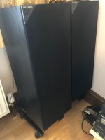
I already had a stereo hifi system composed of:
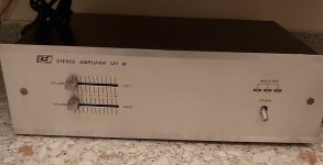
- Advance Acoustic X-i60 amplifier
- Totem Acoustic Mite speakers
The whole system is inserted in IKEA cubes hanging on the wall and suspended 1.5 meters above the ground.

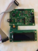
So I assembled the streamer with Raspberry like this:
- Raspberry PI 3 B +
- Official Display Touchscreen 7 ’’
- SmartPi Touch 2 Case
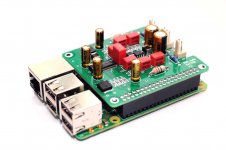
- AUDIOPHONICS Digipi + PRO Digital interface WM8804
- QED Performance Digital Coaxial Audio Cable
- LEICKE power supply 20W 5V 4A
- SanDisk microsd 16 GB
- USB LED to control the shutdown
- Volume as software (2.779 so far)

[240 euros in total]

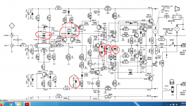
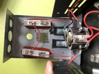
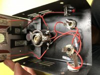
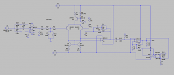
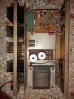
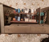
The streamer connects to my amplifier's DAC [the Cirrus Logic CS8416 chip (24 bit 192 kHz) is associated with a CS4344 DAC (24 bit 192 kHz), signal filtering is guaranteed, for the CS4344, by a filter organized around to the operational amplifiers NJM4558 of the manufacturer New Japan Radio Company] via the aforementioned coaxial cable.

After a few months of listening to webradio and Spotify, I am very happy with the purchase.
Some things have happened, however, that push me to an upgrade.
While using the touch display and starting the system, Volumio signaled me an error of "Under-voltage detected!" and a lightning bolt image appeared in the top-right corner of the screen.

I search on the web and I have identified a temporary solution by adopting the CRAAP settings mentioned here:
Archimago's Musings: MUSINGS: Raspberry Pi 3 B+ "Touch" Optimizations; CRAAP Settings, and the "Extremus" Filter Setting.

# Archimago's CRAAP Pi 3 B + Settings ...
arm_freq = 1000
sdram_freq = 500
core_freq = 400
gpu_freq = 300
over_voltage = -3
over_voltage_sdram = -3

# Force max current to USB 0 = OFF (600mA) 1 = ON (1.2A)
max_usb_current = 0

in this way the raspberry is weakened to offer a better sound and the error has never occurred again.
However, I realize that it is necessary to offer adequate power both to the display and to the raspberry plus the Digi HAT in a case suitable for the rest of the hifi system. Finally, I realized the usefulness of a power button that allows me to easily switch the streamer on / off.

I decided to write here, first of all because my skills in electronics and assembly were exhausted with the construction of the first streamer (which is practically child's play, everything is ready for use!) And because I believe that a DYI solution is the most economically sustainable. In recent months I have searched a lot and the idea that I made of the future streamer could be very close to an approach of this type: (I specify that I would like to keep as many pieces as possible made in the first purchase)

Raspberry Pi Hi-Fi Audio Streamer With Touchscreen Control and Max2Play : 9 Steps - Instructables

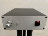
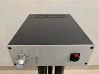
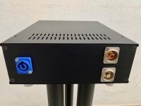
I created a render of what I imagine:
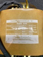
in the front side the touch display, inserted in a ventilated rectangular case, the power button on one side, behind the coaxial socket and the LAN socket, in addition to the power socket of a toroidal linear power supply, a small on / off switch; inside the raspberry, the digi HAT, the linear power supply, possibly all located on the bottom of the case, to avoid extension cables.
My main goal is to get the best possible audio quality with the least expense, in the simplest way possible.

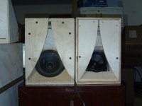
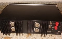
The environment in which the streamer must be inserted is above the current amplifier, which heats up a lot, so the case will have to take up as little space as possible. I attach photos. I specify that it is an IKEA cube suspended and affixed to the wall. The maximum dimensions of the environment are 43 cm wide, 28 cm deep (the same depth as the amplifier), 11 cm high. Considering that I would like to be able to take advantage of the support base of the SmartPi Touch, 18 cm wide, a possible case could be 22x28x10.

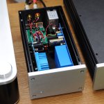
As I said, I read a lot and there are beautiful DIY projects that I found, but with few details on the method, made by people who are experts in electronics, welding, carpentry etc:

HifiBerry streamer in a classic audio case | HiFiBerry
Music Server….my way | Sound&Music Blog
HiFi Streamer : Build thread - Diy Volumio Projects - Volumio
https://theartofsound.net/forum/showthread.php?62839-Audiophonics-RaspTouch-case-with-DigiOne
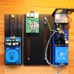
Best way to lay out multiple power supplies (Raspberry streamer)

On the topic "best linear power supply for Raspberry" there are a large number of links and tips:
https://community.volumio.org/t/psu-for-raspberry-3/10012/3
https://musicboxit.wordpress.com/2019/04/24/alimentatore-lineare-raspberry/
https://www.dimdim.gr/2018/03/linear-power-supply-for-the-raspberry-pi-is-it-worth-it/
http://www.raspyfi.com/the-best-raspberry-pi-power-supply/
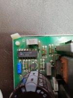
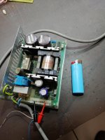
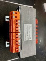
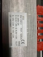
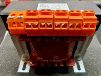
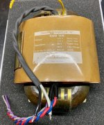
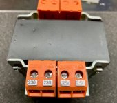
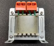
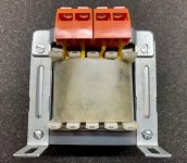
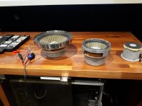
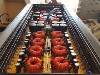
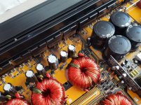
I have a keen eye on the wallet so I have found some PSU from China that could be right for me, honestly I don't understand anything about the differences:
https://www.ebay.it/itm/Assemble-5V...e=STRK:MEBIDX:IT&_trksid=p2060353.m1438.l2649

https://it.aliexpress.com/item/3289...88#3325#6_668#2846#8108#112_668#2717#7565#748

(which is the same but without the connectors)
https://www.ebay.it/itm/HiFi-Walt-J...784995?hash=item594102b1e3:g:QEgAAOSwGTheBwAt

I read that it would be preferable to avoid using the USB connectors present in the first link and to use the stripped cables, but I think it is necessary to carry out soldering. This is definitely the part I ignore most. Do I need something else for power connection?

For the power button I would have found this solution, the RemotePi (only the version for PI 4 is available from their website):
https://www.msldigital.com/collecti...s/remotepi-board-for-pi-4-external-ir-and-led
that together with an extension cable of the GPIO and a ready-made LED button should allow me without soldering anything to have the button together with the HAT (I asked by email directly to them for confirmation, and they said that the RemotePi can power all together correctly with the USB-C socket after the GPIO 18 -> GPIO 17 modification has been done on the RemotePi Board, made by them before purchase).
This solution is particularly convenient, as there is a plugin for Volumio that deals with the software side for the implementation of the various scripts

https://www.msldigital.com/collecti...nated-pushbutton-for-remotepi-board-for-pi-4b
https://www.msldigital.com/collections/all-products/products/gpio-adapter
https://www.msldigital.com/pages/remotepi-board-compatibility-matrix

finally this could be an alternative to RemotePi, but perhaps more complex:
https://www.audiophonics.fr/en/raspberry-pi-and-other-sbc-accessories/audiophonics-pi-spc-ii-power-management-power-supply-for-raspberry-pi-p-11504.html

So let's come to some technical questions with a premise: I have no skills or equipment in soldering, in advanced electronics, in advanced modding of the Raspberry. I am a normal user who has many questions but little experience!
Going into more detail, what I understood is that it would be preferable to separate the power supply of the Raspberry and the HAT, acting on the single pins of the raspberry.
But with my current HAT, fully welded, how can you get such a thing?
Do you think the linked power supplies are valid for what I try to achieve?
What else should I take into organize everything? Shield the various wires inside the case? With what?

But I realized that you don't need a reckocler (like Kali) for the HAT digi:
https://support.hifiberry.com/hc/en-us/community/posts/207749389-HiFiBerry-Digi-Pro-beta-test?page=5

Coming to the case, obviously I am not able to handle aluminum in an advanced way. In your opinion, could wood be a valid alternative? I have seen many projects in this regard, but almost everything involved an aluminum base and a wooden case around it.
I close by saying that I know people who could help me both for the advanced electronic part and for the construction of the case (I hope in wood). I would like to receive advice if the road I am traveling on is right. Maybe someone after me will find it useful.

Thanks!

Greetings from Italy!

Gianluca


Philips 22-AH309 DC amp-interesting antisaturation circuit

Today i found this amp in a not so great state, but it was about 3 dollars so i couldn't resist.Looking at its schematic i saw some interesting features as being a dc amp its thermal stability is important, but the things that set this thing apart in my limited view were the first two antisaturation diodes which were distributed in the first two stages instead of being placed in the first stage.Can anyone shed a more comprehensive theoretical light over this circuit?

Attachments

  • philips ah309.png
    philips ah309.png
    384.5 KB · Views: 402

Sony xm-d1000pf

Having an issue with this amp pulling excessive current. I have my power supply set to limit of 15 amps. When I originally got this amp it only went in protect when applying the remote and it never pulled any current. I replaced the in put and output transistors I got the amp to power up out of protect if I remove the two legs of each rectifier if I connect the two legs of each rectifier the amp Powers up it doesn't go into protect but it pulls a tremendous amount of current and my power supply drops from 14.7 to 8.9 at 14 amps. With the rectifiers removed the amp idles only at 1 amp just fine. If I connect the speaker It don't get sounds from the sub nor does the amps change. Any idea where I need to look at? Thanks

Us amps 3 channel

Just acquired a us amp 3 channel? Not sure the model amazed by the lack of information. Any help is appreciated on identifying it.

Currently has output but only when the rcas are plugged into 1 of the sets of input (not sure of both are inputs yet but I believe 1 is a pass thru)

1 channel had no output the other 2 are low medium range (not as loud as i would expect)

Attachments

  • 16018849567486331842963325818263.jpg
    16018849567486331842963325818263.jpg
    524.1 KB · Views: 56
  • 1601884976532694375161096927828.jpg
    1601884976532694375161096927828.jpg
    567 KB · Views: 56

Altering Attenuator Advice

I have a 4w Vox AC4TV, which I'm trying to bring further down in volume than it already is by patching an attenuator in between the amp and its speaker. I mistakenly bought a 8ohm/15w TubeJuice Attenuator (which I think have been discontinued) when I should have got something rated for the amp's 16ohms. It actually works ok but I've got hold of a 16ohm/100w L-Pad and I'm planning to put it inside the TubeJuice enclosure.

I thought it would be a straight swap for the L-Pad in the TubeJuice but it having opened it up it looks to me like it operates on a different set of components.

Instead of an L-Pad I think it has a potentiometer (its part number comes up as the component in the screengrab) attached to two (4ohm?) resistors. Is that correct? Is that another definition of 'L-Pad'? Is this a 'better' attentuator than an L-Pad?

Can you have a look and tell me if all I need to do is swap in the L-Pad and detach the resistors?

Attachments

  • Screenshot 2020-10-01 at 17.21.11.png
    Screenshot 2020-10-01 at 17.21.11.png
    365.8 KB · Views: 120
  • IMG_4464.jpg
    IMG_4464.jpg
    780.6 KB · Views: 141
  • IMG_4461 copy.jpg
    IMG_4461 copy.jpg
    979.4 KB · Views: 136
  • IMG_4462 copy.jpg
    IMG_4462 copy.jpg
    954.2 KB · Views: 137
  • IMG_4463 copy.jpg
    IMG_4463 copy.jpg
    850.8 KB · Views: 118
  • IMG_4460 copy.jpg
    IMG_4460 copy.jpg
    971.4 KB · Views: 97

Ericcson SMPS

Gooday all,
I have got two of these units, both had a lot of dry joints that I have re flowed. They are adjustable between 45-54VDC. One is working OK, the other cannot adjust at all and sits on 36VDC on the output. Might be some more dry joints or a faulty adjuster. There are two pots, one is for voltage and the other sits next to a CD4069ube chip. I do not know what it adjusts but I'm leaving them alone. Any idea what the VA of these units might be and are they usable for diy amplifiers.I have not worked on smps's before, I know there are high voltages and to discharge the caps before working on them.🙂 Help appreciated !

Attachments

  • IMG_20201001_141410.jpg
    IMG_20201001_141410.jpg
    461.1 KB · Views: 161
  • IMG_20201001_141538.jpg
    IMG_20201001_141538.jpg
    911 KB · Views: 157
  • IMG_20201001_150801.jpg
    IMG_20201001_150801.jpg
    692.1 KB · Views: 155

High pass filter with subwoofer

Hello. This is my first post here, after years of being a member.


I am trying to get a handle on the pros and cons of the following scenarios when running "bookshelf" speakers (6 inch woofer+tweeter) and a subwoofer:


1. Subwoofer with built-in high pass filter,
2. High pass filter or "bass blocker" between the power amp and the speakers
3. High pass filter between the amp and preamp, with the subwoofer still getting a full range signal.


I am interested in advantages and disadvantages (and implied considerations) of each approach, but with a particular interest in whether or not there is a difference in the power demand on the main amp.


I have seen debates in other forums as to whether or not a high pass filter inserted between the main power amp and the primary speakers significantly changes the demand on the power amp, with some arguing that this is only the case when the filter is ahead of the power amp and others arguing that the effect on the power amp is the same in all of the three scenarios.


I guess it comes down to whether or not the power amp has to produce a full range signal when the filter is implemented downstream from it (vs before it)?


Thanks in advance.


EDIT: To clarify, I am referring to a passive filter in all scenarios. Also, unless I am mistaken, scenarios 1 and 2 are effectively the same.

DAC for Raspberry Pi

Hello,
I have developed an new dac for the raspberry pi. About a year ago I built a big version based on the PCM1794 with separate power supplies and I'm still pleased with it. Btw. I still like the BurrBrown sound signature, if there is any, and I prefer it over the newer 32bit dacs. In my ears its more musically and real.

I was wondering how small it can be without lots of compromises in sound quality and started developing a hat dac for the raspi. I chosed the PCM1793 with I had good results in the past. The schematic is nearly the same like the datasheet, except a few changes in the analog filter stage. Here the OPA1642 with Jfet inputs gave the best in my ears. Finally it is ready and with some changes in resistors and capacitors its damn near on his big brother.
A separate power supply is necessary, I'm using linear power supplies for the raspberry and the dac. Other tries with one supply for all failed. So an external power supply for the dac is a must for proper HiFi.

As player software I'm using Moode player. This all is running on a Raspi3.

Attachments

  • DIAL-DAC.jpg
    DIAL-DAC.jpg
    121.5 KB · Views: 2,139
  • PlayerMini1.jpg
    PlayerMini1.jpg
    221.6 KB · Views: 2,325
  • PlayerMini2.jpg
    PlayerMini2.jpg
    343.4 KB · Views: 2,089

What have you built -tried for traditional Karlson in smaller sizes ?

I have a "K5" built by a skilled long-distance friend, scaled from the 1960's Karlson K8, and a scrap "K6" made quickly with my unskilled hands

XRK971 has used 0.43 scale K15.

The Karlsonator and XRK971's "XKi" alignments have dominated the small K-coupler arena.

Perhaps there's still use for little Karlson couplers (most likely supplemented with a little subwoofer)

If you tried one - what driver did you employ? What was your design method? How did it turn out?

Attachments

  • SCRAPK5ANDSCALEDK5.jpg
    SCRAPK5ANDSCALEDK5.jpg
    104.1 KB · Views: 300
  • SCRAPK5VENT.jpg
    SCRAPK5VENT.jpg
    162.9 KB · Views: 296
  • SCRAPK5PA130VSSCALEDK54.gif
    SCRAPK5PA130VSSCALEDK54.gif
    75.7 KB · Views: 296
  • SCRAPK5VSTHEHEAD1.gif
    SCRAPK5VSTHEHEAD1.gif
    72.8 KB · Views: 291
  • SCRAPK5WINGSONOFFZ.gif
    SCRAPK5WINGSONOFFZ.gif
    56.1 KB · Views: 285

6J6 and it's history

Currently I'm reading George Dyson's book Turing's Cathedral in it's 2012 German edition. Chapter 7 describes the development of the IAS machine, an early computer, driven by 3474 vacuum tubes. Among them were 1979 pc. of 6J6 tubes, configured as flipflops. John von Neumann (Johann Neumann von Margittai, as he was Hungarian origin) and his co-designers bought these tubes from WWII military surplus, as Dyson says.
The 6J6 caught my interest, as it has been my very first contact with tube circuitry in my early youth. It's got a rather unusual construction: It has a rectangular cathode sleeve, both triodes were places at the the long sides of this rectangle each. Does anyone know the application(s) it has originally been designed for? And, as the book and some other informations I got gave me some thinking, am I right in my assumption that this tube was the first one with the 7-pin B7G socket, and that B7G tubes in general were preceeding the B9A Noval tubes?
Best egards!

All-in-one portable Bogen Challenger PA

Just scored this guy at the flea market for a very, very fair price. It's a tube-powered Challenger 35A and a matching set of L123C-A speakers ... But the speakers open up like a clamshell and nestle the head inside for transport! It's even got a couple (broken) handles to carry it around.

The seller had already turned it on, so I figured it couldn't do any more damage to run it a bit before I opened it up. As expected, there's a little 60Hz hum (the power supply is a half-wave doubler), but it works! The aux input is working great; the hi-Z mic inputs don't do anything, so I figure the 6EU7 is probably dead. I'm going to rewire that socket for 6N2P, since I've got a pile of those.

Anyway, I've never seen anything like this, and I figured I'd share. I'll probably leave it stock and plug an amp sim pedal into it, at least for now. If I end up keeping it, I may swap the 7868s for something a little more friendly.

Oh, and it came with a Shure 585SA, an AKG D109 lavalier, and a little Realistic lavalier that uses a 7V button battery. Not a bad haul!

An externally hosted image should be here but it was not working when we last tested it.

Analog audio doubled up with TV input?

Sorry, just joined as I am looking for home theatre/stereo answer. If there is a better group in this forum, please redirect me.
Should/could I double up the input from an amplified analog audio signal (from a kareoke mike output) with the analog output from my TV cable box to put back into a single HMDI input in the home theater amp.
That is, I would use a rca Y-cable to combine the two analog signals and then put into a simple converter box from Amazon to get a single HDMI output to the receiver.

This is so I can add a miked sound to the kareoke channel from the TV.
Or will I push some unwanted signal/current back to the TV box?
Already have great kareoke stand alone, but would like to add mike this way to TV too.

Silly question? Blame my lack of experience.

First Shot with a Phono Stage

Hello Everyone,


for my Preamp Project (https://www.diyaudio.com/forums/analog-line-level/359465-time-preamp.html) I've decided to start with the design of the phono stage. I've designed this one based loosely on an old circuit I found at my dad's electronics workshop and some guessed knowledge 🙂


Before I buy components and try to build it, I'd like to hear your opinion. At the moment, it's just a MM stage, I'm planning on adding an MC preamp too.


I'll attach a picture and the Spice File of the schematic, I'm happy to use your comments for improvement 🙂


Regards


Lukas


EDIT: The OP U4 is just outputting a reverse RIAA curve for testing purposes.

Attachments

  • PhonoPre.PNG
    PhonoPre.PNG
    44.6 KB · Views: 155
  • PhonoPre.asc
    PhonoPre.asc
    11.6 KB · Views: 57

ERC Stereo Amplifier 120 Watts - any feedback?

Hi all,

Just got an ERC stereo amplifier for 25€..

From a quick search couldn't find anything in net.

It's a 2n3055 based amplifier with BD139 & BD140.

Anyone got any feedback? Seems quite good construction with module pcbs.

Some photos attached.

Thank you

Attachments

  • 20201004_204216.jpg
    20201004_204216.jpg
    139.4 KB · Views: 161
  • 20201004_204243.jpg
    20201004_204243.jpg
    247 KB · Views: 161
  • 20201004_204306.jpg
    20201004_204306.jpg
    617.8 KB · Views: 173
  • 20201004_204337.jpg
    20201004_204337.jpg
    340.7 KB · Views: 159

Hi there earthlings

Hellooo, I've just arrived here following links as I poked around tintyweb to do with Rauch DVT 250 S amps and of course I've got very sidetracked. This is one of the most interesting forums I've encountered and I'm very old. I'm interested in all of it, always have been. Learn something every day, teach something every day and help someone every day. They are the best days. I fall somewhere in the middle of the quagmire of musician, sound engineer, technician, experimental artist, analogue and digital media, interactive installations and stuff, taught stuff at uni and still always learning stuff. They call me crazy, I get sidetracked a lot and don't make much sense a lot of the time and I'm a bit of a tosser too.. I try not to be. Hmmn, seems I've gone off on one already. I'll just blend in as best as I can, like the sound engineer I am. Wearing black, at the back... I'm open to anything, I live for this whole sound and music thing. It's in my blood and it won't let me go. Looking forward to having some very interesting inspirations from
you all and if I can give back a little then it's all good. So hello....

Headphone Amplifier

To sell a new built Headphone amplifier, based upon the very good design by Per Anders Sjostrom.

Fully working unit, with RCA line in.

Alps Blue volume control.

Neutrik plugs all around.

I will supply the power cable.

Price 225€ plus Shipping (please consult)

I accept Paypal.

Attachments

  • AMP 1.jpg
    AMP 1.jpg
    52.1 KB · Views: 187
  • AMP 2.jpg
    AMP 2.jpg
    48.9 KB · Views: 189
  • AMP 3.jpg
    AMP 3.jpg
    62.8 KB · Views: 179
  • AMP 4.jpg
    AMP 4.jpg
    112.1 KB · Views: 192
  • AMP 5.jpg
    AMP 5.jpg
    122.3 KB · Views: 182
  • AMP 6.jpg
    AMP 6.jpg
    100.5 KB · Views: 104

Technics Vintage Amplifier, Compact Disc and Twin Cassette Deck

Hi there, we have the following vintage items which we would like to sell. Wanted to get your thoughts on possible demand and an idea of fair pricing...? (see attached photos). Many thanks!

i) Technics Stereo Integrated Amplifier, Class AA (SU-V50) - in working order
ii) Technics Compact Disc Player (SL-PG500A) - in working order
iii) Technics Stereo Double Cassette Deck (RS-B66W) - in working order except one cassette player has slight issue
iv) KEF C Series (C40 Type: SP3054) Two Floor Speakers with stands - in working order

Attachments

  • IMG_8605.jpg
    IMG_8605.jpg
    869.9 KB · Views: 80
  • IMG_8606.jpg
    IMG_8606.jpg
    423.9 KB · Views: 68

Tube Power Transformer

To sell 1 Power Transformer with the following charateristics:

Primary: 230 VAC

Secondaries:
1x250VAC 0,2A
1x6,3VAC 5A
1x12VAC 1A

The transformer as been slightly used, but is in like new condition.

Price 70€ + Shipping (please consult).

I accept Paypal.

Attachments

  • TR1 1.jpg
    TR1 1.jpg
    95.9 KB · Views: 108
  • TR1 2.jpg
    TR1 2.jpg
    72.7 KB · Views: 105
  • TR1 3.jpg
    TR1 3.jpg
    90.7 KB · Views: 109
  • TR1 4.jpg
    TR1 4.jpg
    94.9 KB · Views: 109

SMD TDA1541 board... "analysis"

First: No discussions about non-oversampling... Thats another playground... I do it (with JLSounds I2S board).

I fancied one of these new TDA1541 boards with all-around TPS7xxxxx V-regs.

Set it up with just some minor changes:
- NE5534 => OPA1611
- OP42 => ADA4627-1
- replaced all signal caps with WIMA MKPs (<2,5%)
- I/V resistors 1k8 => 1k3

nice crafted board all together, although there are some drawbacks:
- no i2s in-line resistors (typically 33-120Ohm)
- only coax SPDIF receiver
- gets hot, SAA7220 victim

SAA7220P/B #1988
Headphone amp is INA1620EVAL.
Beyerd. DT990PRO

Ebays TDA1387 adapter board with 4 chips sounds better than all my original TDA1541As (4pcs). That is what makes me think 😕

Attachments

  • 2.jpg
    2.jpg
    740.2 KB · Views: 162
  • 3.jpg
    3.jpg
    227 KB · Views: 158
  • 5.jpg
    5.jpg
    418 KB · Views: 161

Amplifier PCB with 4 layers. Right method for signal GND and Pow GND

Im trying to make an amplifier with 4 layer PCB. Many reasons is that one Compliancy, second reduce noise and shorter trace lengths and shorter loops and loop area. Now I have a question is that how to have the ground plane.

Option one: I read it somewhere that to use complete ground place both signal and power ground as one plane.

Option two: Use star ground in one plane for signal and use another star in another plane as power ground and then join them using a 10ohm resistor in the coaxial of both. Stack as Power GND, signal, signal GND, signal.

use ground pour in the left over places of signal plane and then short it to signal ground in both the signal planes.

If anyone has got CE approval with low noise performance with 4 layer PCB please guide me on this aspect.

Help Identifying Tube Amps

Hello All,
Long time member of DiyAudio.com but a first time poster in the Tube/Valve Thread. I was gifted these mono block amplifiers years ago from an elderly gentleman that appreciated and shared my love for music and audio gear. I was told they are 15 watt, Class A push-pull. Based on Google searches they seem to be similar to Heathkit or Zenith kits, all point to point wiring, possibly from the 60’s. Although the chassis sizes are slightly different they both use the same EL34/6CA7 power tubes, rectifier and input/preamp tubes (although they do have different brand output transformers) so I’m assuming they’re just different versions or editions of the same design. I have all of the tubes they came with and a compliment of extras (all used) as well.

I’ve had these for over 10 years and had hoped to refurbish them and get them up and running but haven’t had the time, or any experience with tube gear. I have however built kits from the DIYAudio Store. Can someone tell me what they might be, and what they’re possibly worth? I’d like to sell them because I’m realizing I’ll never have time for them. From what I’ve gathered on line the Hammond Transformers (which are very heavy for their size) alone are “fairly” expensive on the used market.

Any help, advice and information would be greatly appreciated!

Attachments

  • IMG_1874.jpg
    IMG_1874.jpg
    653.3 KB · Views: 224
  • IMG_1875.jpg
    IMG_1875.jpg
    666.2 KB · Views: 219
  • IMG_1877.jpg
    IMG_1877.jpg
    435.6 KB · Views: 210
  • IMG_1878.jpg
    IMG_1878.jpg
    577.5 KB · Views: 209
  • IMG_1880.jpg
    IMG_1880.jpg
    799.3 KB · Views: 218
  • IMG_1882.jpg
    IMG_1882.jpg
    666.2 KB · Views: 145

Exposure 3010S Bias adjustment

Hi All,


I have an Exposure 3010S integrated amplifier for a very long time now and I would like to adjust it's bias voltage.
I've sent an email to the manufacturer asking for the optimal bias setting but there is no response from him (customer service, hello????).
Does anyone can share it's service manual (if there is any) or knows the optimal bias setting?


Thanks

DIY ported enclosure with Tang Bang W5-2143 FR driver vs Q Acoustics 3020i and 3090i

Project goal
To make well designed enclosures with full range drivers for LCR with drivers in the price range of USD150-200 for 3 drivers to use with Marantz NR1510 - 50W/channel @ 8ohm that match the general sound quality that one would get by using the branded Q Acoustics 3020i and 3090i combo and if possible supersede it.

Speaker driver
I've found Tang Bang W5-2143. Reason for choosing this driver is that its 30W @8 ohms, FR with phase plug and has good reviews especially for Mids tonal quality which I think should make it a good center speaker. Since it has a Qts of 0.38 ported enclosure is what I'm thinking. Using WinIsSD to design the enclosure. At the moment sealed Subwoofer to go with them is the plan.

Main question
In terms of tonal quality would a well designed DIY be at least be equal to if not better than the Q Acoustics ?

DIfferential pair transistors

Gents,
I need some help with acquiring reliable replacements transistors for the common pair of transistors - C3200 GR and A1268 GR when used as differential pairs.

I read through numerous threads and datasheets. I purchase at Mouser, most of what is recommended is either not available (either or/complimentary), the gain is way lower than the c3200/1268 pair, or the voltages are not high enough to be substituted in place of the 3200/1268 pair.

In the lanzar opti thread I repaired, it came close to having to replacing the differential pair, but the problem was solved prior to this. I have a couple more Korean amps that came in all utilizing 3200/1268 transistors. I haven't assessed them as yet as see what's required but I'd like to be prepared.
In other parts of the circuit I can work around them but thus far not the differential pair.

all help will be appreciated.

Cheap full range for small test cabinets

I'm looking for some cheapish drivers for testing purposes. (Building an amp) If I blow them I can just buy more and not cry too much. I think they should be 8ohm and rated to minimum 25-50 watts. I can build whatever cabinet is necessary.

I was thinking possibly 75mm - 100mm (3 or 4 inch) full range. It obviously doesn't need to sound hifi with flat extended responses, but when testing, music should sound reasonably like music.

Was hoping to get drivers for about $30 NZD each or less. Including freight. Or if any NZers know a source in NZ.

Any ideas.

From where can these transistors be bought?

I would like to buy some BD329 and BD330 transistors. I found a web-site based in Greece but, for some weird reason, it crashed while I was compiling my order. As this may be the result of a fake fraudulent site, I am very hesitant to order my parts from it. The site is radio741.com which is new to me.

The problem with myself ordering parts are postage prices. I live in Malta, an archipelago of very small islands about 60 miles south of Sicily, an Italian island. I would like to order from a supplier with reasonable postage costs. When I tried Mauser, I was dissuaded by its very costly postage.

Harman Kardon HK980 Cannot power ON

Hi dear members,

I need your help, about a problem with my HK980.

It worked flawlessly until yesterday.
I plugged in new speakers, the BW603, and plugged in the amplifier on power socket. The amplifier did not turn on, like usual, in standbuy mode - an orange light on the power on button, but a white light was turned on on the power button and the tone control button. The amplifier does not respond to commands, cannot be turned on, or turns off on the power on button, the display does not turn on. No ofcourse any sound.
Do you have any idea what that might be? Are the new speakers defective and caused damage to the amplifier?
unfortunately i don't have another amp at the moment to try the speakers.

do you have any idea what it might be, where to start checking? Should I measure the characteristic voltages at some points?

Power stage for piezo-crystal ultrasound transducer.

I need a power stage plus driver to power a piezo-crystal based ultrasound transducer. The operating frequency is 1MHz and the waveform is a square wave of a duty cycle of 25% to 80%.

My initial idea is to use the NE555 IC to generate the square wave at 1MHz, a buffer stage consisting of an emitter follower, and a driver stage consisting of an emitter follower like those usually used for audio amplifiers. The output stage is thought to consist of an NPN and PNP complimentary transistors.

Since, I never built such a circuit I am asking the more experienced to avoid difficult to foresee electronic pitfalls.

The ultrasound power output needs to be known. A formula to calculate the ultrasound power for a driving square wave would be very much helpful and is appreciated.

Need Guidance: High Power LCR Home Theatre Build (Crossover Components)

Hello Everyone,
I am working on a high power LCR speaker build.

The components I have chosen are as follows:
An externally hosted image should be here but it was not working when we last tested it.


The crossover points are as follows:
An externally hosted image should be here but it was not working when we last tested it.


Below are the frequency response curves in REW (var smoothing):
An externally hosted image should be here but it was not working when we last tested it.

Plus I know the woofer is really bad 🙂

Below are the frequency response curves in XSim:
An externally hosted image should be here but it was not working when we last tested it.


This is my first attempt at building a crossover based on measurements and I will need help. I am not taking impedance measurements for this project.

I had to manually trace the graphs using the pictures supplied in owners manual (using FPGraphTracer). Hence, before I start I wanted to check with you folks if there isn't anything crazy wrong with the frequency response graphs? I will also post the pictures next post.

Thank you in advance for your guidance and valuable feedback.

Cheers

Attachments

  • f1.png
    f1.png
    64.5 KB · Views: 94
  • f2.png
    f2.png
    17.1 KB · Views: 100
  • f3.png
    f3.png
    66.3 KB · Views: 79
  • f4.png
    f4.png
    12.2 KB · Views: 73

Rotel RB-960BX - pop sound when turning on/off

Hello, I haven't found too much about this amp in the forums so I though I would ask. When turning my amp on, and when I turn it off, there is a little noise coming through the speakers. Almost like a scratchy pot, and I suspect it's capacitors. Otherwise it sounds great. Would this be more or less the power supply caps causing this or just something totally different? Attached is the service manual and I'm currently trying to find these power supply caps online.

Thanks in advance

Attachments

OPA1656: THD vs. Rs

I want to drive a non-inverting OPA1656 from the wiper of a volume pot -- which means a range of source resistance for the OPA1656 from 0 to <del>Rpot/2<del> Rpot/4. TI has characterized the THD vs Rs for a lot of its recent devices, but alas not the OPA1656 (at least that I could find). There isn't enough info about the topology of the input stage either that could lead one to an educated guess.

Has anyone done any testing or have any other insight about what to expect when the part is driven from something on the order of 5kΩ to 12.5kΩ?

Designing cabinets for high Qts DIY drivers

Hello!

I'm a beginner in building speakers, but I have studied acoustics, and I have some woodworking skills, so I decided to design and build my own speakers from scratch.

I made the drivers (woofers, mids and tweeters) myself also. They don't sound horrible, but they have quite high Qts values. LIMP measurements gave the woofer Qts of something from 1.4 to 2, and Dayton DATS V2 gave 2.1. Usually speaker drivers have Qts much lower than that, and most speaker volume calculators and design tools cannot handle a value that high. I know I could maybe make some open baffle or onken speakers, but I don't want to, because those would have to be ridiculously large.

I have read from some other threads, that there is a few tricks to deal with this situation. I tried adding some acoustically resonant material (wool) behind the cone, on the back of the driver, and it really seemed to lower the measured Qts. Other possible solution would probably be some kind of leaky enclosure.
However, the problem is that I have no idea how big should the leaky enclosure be, so that it would dampen the Q just enough. And also, how much should it leak? Should I just add some small holes, or should I make big holes and stuff them with absorption materials?

Here is some parameters of the woofer (I think the mid driver and tweeter cabinets are probably much easier to design, so I wont include their specs):

Woofer:
d = 165 mm
Qts = 2.1
Fs = 39.4 Hz
Qes = 3.0
Qms = 7.3
Vas = 33 litres

After adding few layers of thin wool on the back of the driver the Qts dropped to 1.6 and Qms dropped to 3.5. Other parameters stayed mostly the same (sadly I forgot to measure the new Vas). I believe that a good layer of mineral wool would drop them even more. However, I don't know if it can also cause some other problems, I have not found much discussion on that.

I'm planning to high pass it from 80 Hz (to leave some room for a subwoofer) and low pass it at somewhere around 800 to 1000 Hz. Hence, the resonance at 39 Hz (if it stays there with the cabinet) would not even be on its range. However, I have no idea if the high Qts (which means that the system is underdamped...?) has some effect on the sound quality on other frequencies also. In other words, should I worry about the Qts if the resonance peak will be high pass filtered anyway, or is it still important to lower it some way?

The text is long and the problem is pretty unusual, but I really appreciate if you have any suggestions or opinions about this. I have invested so much time on making the drivers, that I don't want to waste all that effort by just making some random enclosure for them and hope for the best.

Attachments

  • 20200922_194315.jpg
    20200922_194315.jpg
    930.9 KB · Views: 652

Rockford T1000-1bd eq card bypass

Working on a Rockford T1000-1bd (non CP), and found I had no signal going into the BD card (1325-52874) on Pin 1 (P401-A) of the back header. I checked and I had signal coming out of pin 9 (P200-I) on the front xover header and going into the EQ card on pin 9 (P301-I), but no signal coming out of EQ card on Pin 9 (P302-I) which goes to the BD card input.

I checked the LV + and - and found it pulled down to about +7 and -8 volts (should be about +-13V)

Pulled the EQ card and found I had a short from Pin 14 (S2) to pin 13 (V+) on the DG201BDY analog chip. With the card out my LV is back to +-13V.

I do not have a spare DG201BDY, so while I wait for one to get to me, how best can I jumper from the xover to the BD input, just a jumper wire, or should I use a capacitor? That way I can finish testing the amp (just in case I need to order anything else).


Thanks in advance.
Crazylogix

Self designed balanced output - running into problems

Hi All,

I have been trying to pick a balanced output stage design for my active crossover, and I haven't seen a ton of variety. I made up a test board with a 2 op amp Doug Self design using a single LM4562. When I tested it the THD+N was not good. 90db range. With such a simple design and quality opamp, I was expecting to be in the 110's.

When I look at the design, I'm seeing that it calls for 2 100uf capactiors. In order to find such a high value, I used bipolar electrolytics from nichion. Everything else is good quality surface mount components.

Are the caps likely my problem?
Are my expectations unrealstic?
Are there alternatives to electrolytics I should be looking at for such a large cap?
Am I screwing up something else?

Thanks!

How to find a short in transformer (korean 6k amp)

Hello mates

I'm repairing a big korean amplifier a 6k.

I've done a full rebuild on the PS section. New drivers, new irf3205 which are from reputable source - farnell, gate resistors, pull down resistors and etc.

The problem is that one of the bank, keeps driving the PS mosfets into short. Only this bank, as seen on the photo.
If there are no PS mosfets fitted in this bank, gate drive is good and strong, no problems.
As soon as I fit new FETS - excessive current and the 4 fets which are the one driving the problematic transformer are shorting out.

I've pulled out the transformer. PS section now works but the rail voltage are not correct due to the missing bank of ps section.

There are no solder bridges. I've pulled out the transformer and can't really see if there is a short without unwinding it (i don't think i'm capable of rewinding it).

Is there a way to check if the transformer is shorting out or not ? There is no short between the winds, but i suspect it is shorting into the core ? Any ideas ?

Attachments

  • 2.jpg
    2.jpg
    521.2 KB · Views: 217
  • 1.jpg
    1.jpg
    545.3 KB · Views: 210

recommendations for a small form 2.1ch BT AMP board

guys, i'm chasing preferably a combined BT/Class D 2.1ch amp, which hs a small footprint.

if possible, one with a separate sub channel pot to adjust the output, i sort of cocked up on a small build i'm doing and would really benefit from an adjustable low pass filter\volume, my current setup has an inexpensive 2.1ch amp from Parts Express and a M28 Bluetooth chip from Banggood and i'm getting issues when the volume is up where it appears to be clipping. I'm wondering if it is linked to the DC Step down module, also having an issue with the CE65W i'm using as the 0.1ch sounding a bit average.

I tested it all using the below amp (which unfortunately is too big for this build. This amp lets you pick your low pass frequency and adjust the individual channel volume, which ended up sounding pretty good, just unfortunate i dont have the space or opening to use it now.

Zk-tb21 tpa3116d2 bluetooth 5.0 subwoofer amplifier board 50wx2+100w 2.1 channel power audio stereo bass amp Sale - Banggood.com


sorry for the longwinded question, but i would appreciate any help in finding something around that 50mmx50mm size roughly.

Elekit TU-8200R Stereo Tube Amp Kit

Hello All,

Hope all is well with everyone during this pandemic. I just joined the forum and this is my first post. I bought an Elekit TU-8200R Stereo Tube Amp Kit from TubeDepot online and should be getting it probably next week. This will be my first DIY tube amp kit. I like to listen to music and would like to get the best sound out of this Tube amplifier. My goal is to replace the stock 6L6GC and 12AU7 tubes and coupling capacitors. I need your recommendation to what brand of vacuum tubes is the best and coupling capacitors to get the best out of this amp also are there any other like resistors and electrolytic capacitors on this kit that I need to upgrade? The source I'll be using is the analog output of Bluesound Node 2i and EVGA Nu Audio sound card that has Burson V5i-D opamp and connect it to the 2 inputs of Elekit TU-8200R amplifier. Also what kind a speakers you recommend to pair it with this amp I only have an old Pioneer SP-BS21 bookshelf speaker. Your help and advice is greatly appreciated.

Regards,
Jerry

Arm identification

Hi all - first time poster, long time lurker. I got a new (well, 1983) deck which has an arm with no name. The only markings I can spot are a 5 on the rear behind but not on the counterweight. Can anyone tell me what it is please, and maybe even a bit about it?

Thanks in advance.

An externally hosted image should be here but it was not working when we last tested it.

QSC PL 238 vs Crest 8001

I am aware they're 2 different animals but for portability, although 8001 is cheaper used than PL I wish not to carry a boat anchor in my DJ setup. I was planning on using the Crest as from years ago before these lightweights were used in concerts and permanent installs, but my back is not the same as when I was 25 years old. I wish to use 2 x QSC PL amp used market for a full range and sub for my DJ rig (BFM 12 Omni Tallboy/ Double 2226 loaded diy sub). In comparison my question is the Crest give better bottom end and more ump than the PL. Can someone maybe give me a little education between these 2 amps.
The subs hp at 40Hz(40-100Hz sub). Thanks!😕

Experiences with external devices that keep voltage steady?

I get a split second voltage sag (aka brown-out) when my roof mounted air conditioner unit kicks in, which cuts the audio from my vintage Pioneer M-22 amp for a second. We've had the sag since we bought a new unit four year ago, and it's never switched anything off or cut out sound, but now I have this amp which is susceptible to power fluctuations.

Our air conditioner tech took a look, he said the compressor is drawing a lot of power when it first kicks in (which apparently isn't unusual) then stabilizes, so he's not surprised by the momentary sag. He recommended getting an electrician to look at the breaker panel and wiring (which are not old). Speaking to a few electricians on the phone, they all have different theories, and I'm reluctant to get into the expense of a wild goose chase if this ultimately can't be fixed?

It's worth mentioning that it's a Japanese amp, so I'm using a step-down converter to feed it 100v. I could dump the converter if I had a variable device I could just set to 100v.

I know the ideal solution would be something like a PS Audio Power station (AC regenerator), but I don't want to spend a few grand. I'd rather spend a couple of hundred, tops.

There are uninterruptible power supplies, which are often used in the computer arena (kicks in a battery if the voltage is lowered) but I don't know how well that would get along with a 30w amplifier?

There are also variacs, constant voltage transformers and servo transformers, but I've no idea if they're ideal for this application? I hear CVTs are noisy.
Projects by fanatics, for fanatics
Get answers and advice for everyone wanting to learn the art of audio.
Join the Community
507,804
Members
7,889,065
Messages

Filter

Forum Statistics

Threads
406,271
Messages
7,889,065
Members
507,804
Latest member
m-tagg