Ground loop or else?

My amps making buzzing sound from my speakers that when i put my finger to the negative terminal (banana plug. Exposed) and to the chassis, it stops. The sound is verrry feint and also is the hum that disappears together making the amp pretty much dead quiet.

I have back to back diodes that connect the psu gnd of the amp to the chassis and the earth terminal, and after i added a 1.5k ohm resistor parallel to the diodes the buzzing noise stopped.

My questions are-

was this a ground loop issue or more likely an oscillation?

And instead of the 1.5k ohm resistor can i try a small cap? Because i dont like the way the resistor changed the sound.

need little help with new els

Hi All.

7 years ago i build some els and they have served me very well until last week when my 2 cat´s took a nasty fight and overturned the one els and it is now dead for ever🙁 so i will build new ones, i will this time try and make them with wire stators instead of perforated metal sheets and now i have some questions i hope you great guys can help me with.

first what is the best way to connect the wires? i have take a picture of differents connections methods of the wire but what is the best way?

second can i avoid membrane support if i make the panel 120cm (47 inch) high and 15cm (about 6 inch) wide my d/s will be 1.5mm (0,060 inch) my old panels was 100cm (39inch high) and 22cm (8,6inch wide) and was suppoted every 10cm(4inch) i know the rule of thump what the membrane support shall be around 70-100 x d/s, the panel i will make is high and narrow so is supports required? i will again go hybrid and my crossover frequency will be in the range of 250/300 hz and cutoff 24 or 48 db.

wire i plan to use is awg20 solid copper core with pvc isolation
i will use wire suppots every 10cm (4 inch) is this ok?

membrane material is 6um dupont c mylar stretched 1%

coating is again varmason statguard floor polish.

thats was all for now.

LS

Attachments

  • 20201111_184934.jpg
    20201111_184934.jpg
    357.2 KB · Views: 159

What followed me home/do you recognize connector?

Pictures are of an item I got for free off of online classifieds described as "800W amp for home theatre". It is a strange beast, obviously chassis rescued from another complete system. It is 2 channel input, labelled L and R, but 3 speaker terminals.
Punching in numbers into Google yields nothing but "Panasonic" and "subwoofer".
Looking it over, my guess is it is rescued from a 2.1 home theater system. There is 1 huge amp module and 1 narrower, longer module.
I think a big clue as to what it might be would if someone could recognize the 25 pin connector in the picture. I think that is likely a proprietary audio AV interconnection such as several manufacturers have had in the past.

Attachments

  • IMG_20201112_135540801.jpg
    IMG_20201112_135540801.jpg
    723.5 KB · Views: 101
  • IMG_20201112_135556122.jpg
    IMG_20201112_135556122.jpg
    618.3 KB · Views: 96

FS: ModuShop (HiFi2000)/DIY Audio Store Slimeline 2U Aluminum chassis with hardware

Selling my 2U all Aluminum chassis from DIY Audio Store (ModuShop - HiFi2000). Width is 415mm, depth is 350mm. Comes with internal baseplate for easy mounting and cutouts with all necessary hardware installed: front panel Power Button w/LED, 15A Power Receptacle, 15A Fuse Holder, 3.5mm Jack, and four channels with Neutrik XLR Inputs and Dayton Audio binding posts.

Case itself is in very good condition cosmetically. Will ship assembled.

Asking $150 plus shipping cost.


***See my other for sale thread for Hypex NC252MP and NC502MP modules...great paring!***

Attachments

  • PXL_20201112_205633352~2.jpg
    PXL_20201112_205633352~2.jpg
    561.3 KB · Views: 388
  • PXL_20201112_205613651~2.jpg
    PXL_20201112_205613651~2.jpg
    521.4 KB · Views: 321
  • PXL_20201112_205250329~2.jpg
    PXL_20201112_205250329~2.jpg
    926.7 KB · Views: 292

Allison CD 8 recap question

Hello I have a mint pair of CD8s in oak and have a a few questions regarding upgrading caps and resistors. In the first picture you can see they installed two 60 mfd caps Is there a reason for this or can i just replace with a single 120 cap? They also installed two 1 ohm resistors in parallel. should I install new 1ohm resistors the same way?

On the bank of resistors on the left side should they remain the same 1.5 and 2 ohm or can they be replaced with all the same ohms (1.5 or 2 )

These are great sounding speakers but lack a little punch compared to my Allison 7

Attachments

  • cd8 cap and resistors.jpg
    cd8 cap and resistors.jpg
    914.6 KB · Views: 139

DCX 2496 Selectronic outputboard

Hi
I got a question, I have an old Selectronic output pcb for a DCX2496 and wanted to replace the original Behringer output pcb, there are 3 pins on the Selectronic pcb that have to be connected to the psu and the main DSP pcb, written on the Selectronic pcb is pin 1 PSU 6, pin 2 DSP 6 and pin 3 PSU 3, want to be sure that I read that correct, pin 3 direct to psu on the third connection, that is 9 volts, pin 1 comes from 6th connection on psu and then goes to DSP coming from pin 2 of the Selectronic pcb, is pin 3 only connected to Selectronic
pcb or also to main DSP board? I think both, can anyone give me schematic, I seem to have lost it,
Cheers, Tom.

FREE: Hypex UcD 180ST

It went to the first forum member who claimed for it.
Thanks to all those interested.

I have one leftover Hypex UcD 180ST .
It was working last time I connected it a few years ago, but I cannot assure it will be in working condition because I do not have proper SMPS to test it, although it should work properly.

It will be FOR FREE.
If there is any interest you only have to pay for shipping.

An externally hosted image should be here but it was not working when we last tested it.

Speakers-almost done, built around Bohlender Graebener RD-50s

These are my almost done, kind-of line source, two way, sealed, crossover-less speakers. They're built around RD-50 planar magnetic drivers in sealed enclosures. The bass is handled by what I am calling subwoofers, although they don't go down quite to 20Hz. The cabinets use activated charcoal in a similar way KEF uses it, to enlarge the apparent volume.

The crossover frequency is 200Hz handled by the preamp. The bass module is intended to be raised off the floor in line with the larger speaker, directly above it, see drawings and the visions in my head.

The subwoofers are two drivers each, firing opposite and in phase. When music is pumping, there is zero vibration in the cabinet, they cancel internally. These are Tang Band W8-2022 8" drivers.

The big idea is that these speakers should have as little getting in the way of the sound as possible. A single driver would be ideal for the spectrum, but the RD-50 is a pretty darn wide range driver.

They sound great, and that's a good thing because they took me quite a long time to put together. From initial design in 2013, I noodled on the design until I was ready to move into Rhino to draft all the plywood and aluminum pieces. Working off and on, I got them to this point at the end of 2019. I aim to post again once they're really done!

The design calls for the main speaker to be suspended over the subwoofer. The aluminum plate legs will be brazed to the subwoofer aluminum arms. That will be a rigid connection. The main speaker is intended to be suspended with neoprene or other bands as the drawings show and one day will be! I don't know if this will work or make a difference vs being rigidly attached. The screws and rivets of the driver are intended to be covered and flush out at the level of the adjacent plywood.

The original inspiration comes from my interest in the characteristics of line sources and line arrays. The 50" driver acts like a line source, but I realize the best line source would be floor to ceiling. However, locating the driver between about 22" and about 6'-0" gives a good range of sound vertically-sitting or standing. I love the look of plywood laminations and black metal. I sanded and stained the laminations with Osmo-great stuff. I may have first seen this with Magico's M-1, but there are a lot of nice precedents, such as Jean Nouvel's Philharmonia design. To that end, I sourced 1" thick American Birch, no void (actually low void) plywood.

Plywood was cnc'd by a local shop in Portland, which did a great job. What remained for me was a mammoth sanding job, mostly by hand, that took months. I would not recommend it. In fact, I wouldn't exactly recommend any of this! I value the encouragement I received from members of the Portland Audio Club along the way. Wish I could host people at home to hear them.

Attachments

  • 01-.jpg
    01-.jpg
    527.4 KB · Views: 370

Good quality to-3 sockets needed

Hello all.
I'm in the progress of building the leach superamp and have been trying to source some good quality to-3 sockets like schaffner km 340z, but they're discontinued all places I looked, ebay has some noname but to be honest they look really cheap, and I would appreciate a stable contact between transistor and socket permanent, any suggestions? I've been considering to solder wires directly, bad idea?

Possibly silly idea - Opamp input-Triode w/ Cathode Follower Output RIAA Phono Stage

The problem I'm trying to solve is how to make a tube phono stage that will be friendly to current-issue moving-magnet phono cartridges that expect low input capacitance (specs claim input load C should be 250pF, including cable capacitance, strays, and preamp input capacitance).

The obvious solution is of course 'use an opamp'. So....

Why not make the input stage a good opamp like OPA2134, and make the output stage something like a 6DJ8, with the EQ in the middle?

I searched for something like this, and even though I know I can't possibly be the first person to think of this silly idea, I couldn't find much along these lines.

I found this:
Opamp + tube RIAA board art – wauwatosa tube factory

I also found that (of course) John Broskie has played with the idea, here:
Phono Preamps at Last

This interesting circuit is described in that TubeCAD article:
hybrid_phono_active-passive_riaa_eq.png


What I dreamed up is much less clever. But will it work? It seems so simple.

Will the approximately 60mV DC to the grid of the second stage 6DJ8 cause problems? Will the opamp output need to be RC-coupled to the 6DJ8? (attached schematic)
--

Attachments

  • Hybrid_Opamp_Triode_RIAA.png
    Hybrid_Opamp_Triode_RIAA.png
    16 KB · Views: 309

Any info on Wharfedale W2 Dovedale?

I'm looking for any info people might have on the above. I got hold of a pair a while ago and having recently got rid of the weird treble attenuation pot in the crossover am increasingly impressed with them.

They are labeled as made in England by Rank Wharfedale in Idle, Bradford Yorkshire. There is next to no info on the net.

They are an interesting design, a 2 way system with one 12" and one 5", giving quite remarkable treble response from the 5.

The drivers are very well made, strong cast baskets on both and enormous magnet assemblies on both also. The magnet on the 5" would be around 4" diameter. Both are labeled 10-15 ohm.

One interesting thing is that the 5" driver is in it's own, very small, sealed section of the box.

Partly I'm asking as it's simply nice to know things about what I've got, but also because I'll be moving back to Australia next year and if they or just the drivers are well regarded I may think about shipping them home with everything else. Particularly if the drivers are well regarded I may just strip them out of the boxes.

At the moment I'm quite enjoying the sound of them but it's a little hard to tell with a low end amp and an iriver (like an ipod)...

I particularly like to get a figure for their efficiency.

Cheers.

Driver choice for digitally controlled high-efficiency 3 or 4-way

Hello forum,

I'd like to tap your experience and creativity since I am in the process of meditating about my next speaker project. Be warned though, it might get a little exotic (and maybe ambitious).


Since this is a project description, I think it might be good to give you some background, so you know where I'm coming from and what I'm aiming for.

Starting point:

I'm currently listening to a pair of computer controlled 3-way speakers that I designed with a friend in 2010 to take part in a diy hobby loudspeaker developer contest. It was designed around Acourate and tried to demonstrate what was possible with digital technology. We accepted a few compromises back then.

Hifi-Music-World 2010 - Messebericht - DIY-Forum - Frank-Landmesser.de

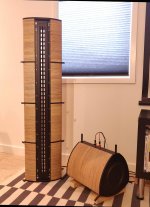
Scroll to the bottom to see Zoé.


General concept: drivers with substantial cone area in a very small footprint. Zoé measures just 24 cm wide, 42 (top) / 52 cm deep (bottom) and 95,5 cm tall. Yet it houses

38 mm tweeter: Ciare 1.38 TW2
20 cm mid-woofer B&C 8NW51
38 cm bass Beyma 15G450N (mounted on the side, playing in something like 30+ litres net).

Linear phase crossovers and room correction are provided by AudioVero Acourate software. Initially with 200 dB/octave Neville-Thiele XOs, now with proprietary filters developed by Uli Brüggemann, Acourate's programmer. Similar steepness though.

The cabinets were build in record time by my buddy, to get finished speakers in time for the competition. For years I thought about exchanging it for a new housing with more wallthickness and a nicer finish.

However, if I spent money on a nicer cabinet, I could as well improve the concept a bit to overcome some of the limitations of the system:


  • The tweeter hardly reaches 15 kHz. A trade-off for its massive cone area and Mms.

  • Beamwidth/directivity continuity might be a bit flawed because of the big step from a 20 cm mid driver to a dome tweeter.

  • While Zoé plays really nice now, I can't get rid of the feeling that I might get more mid/high resolution with smaller, lighter drivers.


For years I thought about ways how to improve the concept in the current footprint and design, but finally I came to the conclusion to keep Zoé as it is and start from scratch with a completely new design for the next digital speaker.


I have sets of mid drivers that I wanted to use in a design for many years. It might be time to build something around them now:

Beyma 102Nd/N
https://www.beyma.com/speakers/Fichas_Tecnicas/102NdN.pdf

25 cm mid drivers with a BL of 25,4 Tm, driving 33 g Mms in an 11 mm deep gap with a 12 mm long VC. This results in Qes of 0,09 and a monstrous efficiency rating of 103 dB/2,83 V/1 m.

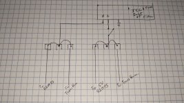
I plan to use two per side. :goodbad:
Symmetrical driver placement for good measure...


The challenge is finding the right partners for the upper frequencies. While I don't care much about their efficiency (as long as they are not on a completely different page than the mid monsters), I am looking for decent surface area and low moving mass.

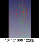
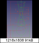
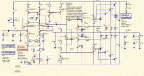
That quickly brought me to small PA drivers or even AMTs for high-mids and a ribbon tweeter. Here are two quick drafts of how this could look like:


I'm curious to read your thoughts and ideas.

Two TPA3255 Amplifiers HiFi Builds

I'm thinking about building a dual TPA3255.

Has somebody built one?

Proposed build.

1. 2x TPA3255 high quality stereo amplifier boards that can be configured in mono mode each for Left and Right stereo signal input through each amplifier bridged to single mono output.

2. Power supply would be high quality 48VDC continuous 1200W ouput design.

3. Balanced left and right inputs

4. Possible audio input processor card in parallel by switch on audio input signal path, off a switch control for WIFI 6 AX blue tooth 5 wireless signal receiver and sound processor/DAC.

5. Enclosure would be all aluminum with heat sink design make contact with aluminum enclosure by physical heatsink contact with TPA3255 IC and the enclosure.

6. Enclosure would have thermal transfer fins on sides with flat surface on front and rear . Top would be natural wood finish covering power supply unit with clear glass for visibility to left and right dual TPA3255 amplifier boards.

7. Would use liquid metal thermal insulate material where possible and high thermal transfer pad material if necessary. Bottom side of enclosure would have filtered passive filters and so would back side of case.

8. Overall dimensions would be for smallest foot print on all sides.


Is the technology available for my proposed dual TPA3255 build?


Thanks.

Have I gone for the wrong drivers???

Hi everyone I’m a very novice diy speaker builder and having some trouble trying to build some speakers with tannoy drivers.
I did a bit of research and decided on using tannoy 2062 drivers (from the tannoy i8 pa speaker model)
I read that they are very similar to the tannoy sandringham model that goes down to 39hz and also that the sound quality is very good with the classic tannoy sound so thought...brilliant! I’ll try to make something similar.
I’ve got them in 47litre ported enclosure of a floor stander type.
Problem is I’m finding for one, by putting a sine wave test tone through them the frequency drops very quickly below 60hz, and I have to turn the mid down quite a bit to get the bass to come through. Also I can’t “feel” the bass that much and the bass I can feel is quite airy, if that makes sense.
It’s a a 47 litre enclosure with two 5cm diameter x 2.5cm length ports.
This is what I got from a speaker calculator online.
I do have the specs for them if anyone is able to help.
Quite gutted as I’ve spent quite a bit of time on them but just don’t seem to be getting very far with it.

Building the Elusive K Amplifier

This is the story of building the Elusive K Amplifier. It’s a personal journey that started with a strong desire of building a power amplifier and ending with studying psychoacoustics and perception relativity.

It's a dual mono, fully differential, balanced, no capacitors in the signal path, no global negative feedback, class A amplifier.

Being biased at more than 7 A per channel it’s a muscle amp capable of driving very low loads with ease.

It sounds super clear, crisp and musical in the same time. The imaging is immersive, play a good recording and it will take you there.

But this is not about building the best amplifier, or the most powerful or anything like this, instead it's about encouraging the less experienced amateurs to summon up their courage and start building something, anything.

As you’ll see, I’m myself a newbie in electronics, but despite this I managed to make an amplifier that makes me real proud.

This has a lot of content, more than 250 pages of text, graphs, and images. Since it was too big to paste it here, I divided it in six parts:

Intro
First Stage
Power Stage
Building it
Measurements
How does it sound?

These self-explanatory titles were written in the order listed above, like the chapters of a book, and is best to maintain that order when you read them.

I’ve attached some schemes and picture of the build, but you’ll find much more inside. Also, you can see the original pictures here.

Most schematics presented here can be simulated in the browser with only a few clicks.

Attachments

General advice for first full diy

Looking to be talked off a ledge or to be encouraged to jump. I tend to go a little overboard, so I want to make sure I'm only biting off only a little more than I can chew. I'm all for a bit of challenge but not in for a suffer-fest or pounding my head against EE nuances.

Background: I have very limited diy experience with a bottlehead crack and a pass aleph j with a dual mono fed power supply. I had a 45 SET that I bought but has since been sold with the idea I'd replace it with something I built. Speakers are single driver 98db / 8 ohm Omega 8" floor standers. (Does anyone have an impedance curve?)

Desirements; Not too complicated of a circuit, Single Ended, ~2-6wpc (I don't listen loud), but with good frequency response. One of the reasons I sold the 45 was it rolled off a little too much for me on both ends but especially on low frequencies. With the help of another member here, a frequency response plot confirmed what I was hearing (or rather not hearing). Also, this is as much about building a decent sounding amp as it is about learning and getting a feel for what some other tubes might sound like. My hi-fi experience is very limited. I value soundstage, presence, and relaxed sound I can sink into over an ultra precise reproduction or sparkling highs. I listen to all sorts of music, but mostly rock (60%?) with the remainder evenly split across things like singer/songwriter vocals, jazz, classical, opera, country/folk, and electronic.

Initial Thoughts: Originally I was thinking about buying another bottlehead kit, and will likely do that in the future, but I came across this page to build a seemingly straightforward EL84 based amp in a switchable UL/Triode config called the "El Mighty Cacahuate". Started to think I'd build it straight from the schematic but then I realized I have a few 6SN7's leftover from that other amp as well as one or two 5Y3's that I could use to reduce cost. One of the 5Y3's is actually a 6106 Bendix IIRC. Then I started to look at the OPT he spec'd and wasnt super keen on it due to its low Inductance and how that would roll the low frequency, like what my 45 used to do. Then I got to reading and am wondering about switching the EL84's for EL34's for a bit more power, and it seems to be preferred over it's small sibling, and then all would be right in the world with this OCD mechanical engineer with using 4 octals.

With the EL34's this has led me to looking at something like a Hammond 1630SEA or Edcor CXSE25-3.75K with an OP of around ~315-330v B+ / 70mA / -15v g1, depending on if I use the 5Y3 or stick with the 5U4. I'm also having trouble finding the triode tube curves for the EL34 to know if I've got the right values for all of this. Does this all look right / can anyone point me to one? Further, the PT spec'd on that blog will also be upgraded to one with a higher current rating for the EL34's.

All said and done, it's turning into something that will require using iron that will likely cost ~as much as it would have taken to complete originally as shown on the blog. Hence the part earlier about going a little overboard on my projects. This EL34 would likely make a good compliment to whatever kit I'd get from bottlehead down the road using either a 2A3 or 300B. Am I being rational here? Should I go for it or is there another amp to consider? Right now one with a good schematic and/or a few pictures of the completed design would really help.

FS: Millet LR Phono Preamp

This beautiful sounding phono preamp was my constant reference thru many other phono builds. I recently added the Jensen MC transformers but, without a MC cartridge have not listened to them.
Phono and power supply boards built per Millet’s article - AD797 ic’s, Cinemag coils . LR Phono Preamp
Enclosure is a Par Metal case.
$400, includes shipping to CUS only
PM if interested. Thanks.

11/12/20 SOLD

Attachments

  • A5520AC5-4951-478B-A017-00D73BA9C479.jpeg
    A5520AC5-4951-478B-A017-00D73BA9C479.jpeg
    422.1 KB · Views: 323
  • F3C8C45C-E84F-4D0F-A94B-B0BFAB05AF3D.jpeg
    F3C8C45C-E84F-4D0F-A94B-B0BFAB05AF3D.jpeg
    394.2 KB · Views: 316
  • 815D7F20-8E05-449B-B174-DA81FF62277C.jpg
    815D7F20-8E05-449B-B174-DA81FF62277C.jpg
    552.7 KB · Views: 312
  • E85BFDAD-3BB7-48CB-998B-5A8815A3C0C8.jpg
    E85BFDAD-3BB7-48CB-998B-5A8815A3C0C8.jpg
    526.7 KB · Views: 316
  • 28AD3416-E798-468F-9F94-26AD17C467BB.jpeg
    28AD3416-E798-468F-9F94-26AD17C467BB.jpeg
    862.7 KB · Views: 318

basic class A

This is an amplifier I design, after studying many available designs.
Output stage complementary – darlington T3 – T6 –T7 – T8
Output bias current set with T4 – T5 ( mounted on heatsink )
Voltage gain T2 and bootstrap C6 – R10 – R11
Input & AC feedback T1 – R6 – R7
DC feedback OP1 – R4
Is there any hope for this design ?
Should I select transistors, recalculate everything and start building and testing ?

Attachments

  • basiclassa.GIF
    basiclassa.GIF
    19.7 KB · Views: 1,032

Fountek NeoCD2.0 or NeoX3.0 for 3-way with 8" mid?

Hello forum,

I'm trying to decide which ribbon tweeter to buy for a modification of my current 3-way speaker. The mid driver is a B&C 8NW51. Crossover is handled by software (Acourate by Audiovero with linear phase 200 dB/octave filters and time alignment).

NeoCD2.0
NeoX3.0

While I do favour the higher (claimed) SPL of the NeoCD2.0, I am a little worried about the vertical directivity from a 120 mm high tweeter. NeoX3.0 looks friendler here with 80 mm height, while its width is still a narrow 12 mm. (8 mm for NeoCD2.0).

The speakers are currently playing with a Ciare 1.38TW2 dome tweeter. Sd is 1135 mm² for this 38 mm dome. Both ribbons have 960 mm2, so would be equal to a 34 mm dome.

The 8NW51 can handle 2 kHz without problems, and an even higher crossover point might be possible - but I have to listen to that with a bunch of different filters for a final decision.

Could anybody even compare both ribbons?

Thanks in advance!

SMPS500R Auxiliary Voltage

For those of you familiar with the Connexelectronics SMPS500R, how can the auxiliary output be changed from +/- DC to single DC voltage?

My unit is slightly different than the documentation in that the main outputs are next to the two larger caps and are spade connectors.

Also, should I be concerned about the two Samyoung SMK 63v 4700uF caps and one Lelon 200v 1000uF cap? This is the +/-60vdc model, so should those two caps be at least 80v?

Attachments

  • F6394958-F524-4FA7-99F8-B8D63FC48588.jpg
    F6394958-F524-4FA7-99F8-B8D63FC48588.jpg
    675.8 KB · Views: 165
  • 8DE3AC3B-FB4A-46C9-B04E-C7E12C300C34.jpg
    8DE3AC3B-FB4A-46C9-B04E-C7E12C300C34.jpg
    837.6 KB · Views: 171
  • 6D82AA8B-4F29-4476-9C32-37A53BBDB348.jpeg
    6D82AA8B-4F29-4476-9C32-37A53BBDB348.jpeg
    261.4 KB · Views: 166

LM2596 Regulators

Hi Guys
Was wondering if anyone have actually tried this for your audio
projects. Bought a couple ready made at dirt cheap price to play
with. Since voltage is adjustable would it be a good idea to use
it as a preceeding stage to a linear reg. My thinking is that noise
might be lower then with single stage of regulation but with no
scope don't really know if the Lm regulators are really low noise

Thanks

  • Locked
[FS] Soekris DAC1541 in mint condition

SOLD!

Hello

I am replacing various components in my system, and in particular I am parting with my Soekris DAC1541.

This is the original fully balanced discrete sign-magnitude design by Søren Kristensen that uses two pairs of R2R strings in place of a single pair to get the hot and cold wires of the balanced signal. The last price was 1150 EUR plus VAT (25%), i.e. 1437.50 EUR. The Soekris DAC2542 in comparison has only a pair of R2R strings per channel, generating a unbalanced signal from which the balanced out is obtained using opamps. Also, the older model has higher precision resistors.

My DAC1541 is in mint condition, no scratches, and is in absolutely perfect working condition. It comes in its original packaging with all original included accessories and printed manual. No pets, no smoking in my household. Pictures can be found here: Soekris DAC1541 — ImgBB

I am looking for 1000 EUR (total price, no need to add VAT) including shipping to Europe and an Apple Remote to control it. I will throw in a EUPEN power cord I terminated myself and everything will come doubly packaged.

There are a few references to me in the "good guys" threads at pinkfishmedia – people have bought from me Apollon NC500 based monoblocks, Abrahamsen amplifiers, Naim olive NAC 32.5 and chrome bumper NAP 140 and cables, and a few more items.

MG-1 rebuild and upgrade to 1.7i

I found a pair of somewhat decrepit MG-1s on EBay for $75. I picked them up, brought them home, and got started.

Magnepan has been making MG-1s since the 70s. They got renamed to the MG-1 improved, then MG-1a, MG-1b, MG-1c, 1.4, 1.5/QR, 1.6/QR, 1.7/QR. QR for "Quasi-Ribbon," which means no more wire, aluminum tape instead. The magnet structure never changes. I'll be replacing the diaphragms and using tape instead of wire, so these will be 1.7s when I'm done. I'll also build a new frame - I'm unimpressed with the sheet metal frame. When I do that I'll change the dimensions from the MG-1 standard 60x22 to the 1.7 standard 65x19. The oak trim is gone forever, I have different plans for these guys. I'm going to make them look more or less like factory 1.7s, not exactly the same but close.

I expect this to take a few weeks. I'm not completely ready to do this, I have a couple tools yet to make to facilitate this. I will be documenting it as I go along, with enough information to allow others to follow. If you have a good shop, anyway.

Pictures below:

1. The "new" speakers. Pretty grungy looking. No bases. Holes in grill cloth a mild concern.

2. Remove the Oak trim, which I think looks very 70s. It won't be coming back.

3. Speaker 1. Note the mashed up wires. There's a rip in the diaphragm behind the wires. This one needs a new diaphragm.

4. Speaker 2. Also a very small rip in the diaphragm, hard to spot in a photo.

5. Closeup of the rip in speaker 1.

6. The stereo pair. This is the "front." MG-1s play through the little holes in the metal. I'll be changing that.

7. The stereo pair. This is the "back." After the rebuild it will be the front. Notice that the speakers are mirror images. This lets you play for hours and hours deciding if the tweeters go inside or outside.

The wires are magnet wire. The tweeters are about 7 meters of 32 gauge aluminum. The mid/woofers wire is doubled up, so it's 54 meters of 24 gauge copper.

Tape is better than wire because when you drive the mylar over a larger area the distortion drops noticeably.

The magnets are flexible ferrite, .060" thick, 1/4" wide (mid-woofer) 1/8" wide (tweeter).

I'm not sure what the mylar is because it has a thick coat of 3m-77 and milloxane. I believe the milloxane is to damp diaphragm vibrations. I'll be using .0005" mylar and I expect to have a final coating of 3M 30NF, which is a longer lasting substitute for milloxane. 3m-77 is a poor choice and the cause of delamination in older magnepans; a better choice for wire would be DAP Weldwood contact cement, which actually lasts. But Jim Winey worked for 3M before he started Magnepan, and being from Minnesota he apparently believed anything from 3M was better than anything else. I'm from Green Bay, so I think something very different about Minnesota.

Attachments

  • MG-1a11-15-19.jpg
    MG-1a11-15-19.jpg
    507.3 KB · Views: 552
  • MG-1b11-15-19.jpg
    MG-1b11-15-19.jpg
    326.3 KB · Views: 507
  • MG-1c11-15-19.jpg
    MG-1c11-15-19.jpg
    302.9 KB · Views: 666
  • MG-1d11-15-19.jpg
    MG-1d11-15-19.jpg
    268.2 KB · Views: 601
  • MG-1e11-15-19.jpg
    MG-1e11-15-19.jpg
    468.7 KB · Views: 632
  • MG-1f11-15-19.jpg
    MG-1f11-15-19.jpg
    258.7 KB · Views: 379
  • MG-1g11-15-19.jpg
    MG-1g11-15-19.jpg
    446.3 KB · Views: 768

Icepower & Khadas DAC "burning amp"

I want to build a compact desktop DAC+amp for a pair of full-range Alpair speakers. This is my prototype: Khadas DAC wired to a Icepower 50ASX2 amp.


An externally hosted image should be here but it was not working when we last tested it.

I put a SSR 2A relay to power ON the amp when I switch on the PC. And here came problems:
1) the SSR (Omron from eBay) is not switching on the amp. I wired the AC wires bypassing the SSR - there's a switch at the mains socket.
2) now when I switch the PC on or off when the amp is on - there's a thump in the speakers.
3) the amp is too powerful for the speakers - I control the volume in Windows and 5% is the maximum for comfortable near field listening.
4) and now the most dangerous problem - once when I turned on the amp the PC immediately switched off and it turns out that somehow the amp burned the South bridge chip in the motherboard.


Can I connect the 5V wires from the Khadas DAC to the "enable" pin on the Icepower ?
Can I add a 50k volume pot between the DAC and amp ? I have an Alps 50k stereo pot.

And what happened so that the amp literally fried the motherboard ? How to prevent this from happening ?

Warning: Nakamichi plugs made of IRON

I discovered that Nakamichi banana plugs and spade terminals are gold plated iron, NOT "pure copper" as advertised. Note that it appears that Nakamichiplug.com is NOT associated Nakamichi.com; I have no issues with Nakamichi (the real one) gear. I have seen several postings on this forum and others about using Nakamichi banana plugs and other connectors, and wanted to let folks know that they are an overpriced piece of gold plated iron. Hey, they look nice, and the moderate price would make one think that they're getting a good deal. Nope. 😡

Discovered by breaking a tip on a spade plug trying to get it to fit an 8mm post; copper doesn't snap like that and upon magnification is definitely not copper by looks. Filed down that piece, and sample filings on other pieces and also some banana plugs, discovered all were a gold plating on copper plating on soft iron. Finally verified it by dropping it in some hydrochloric acid, and as expected the iron reacted (slowly). (Don't have any nitric acid to test with which is very reactive with copper but not as much with iron.)

FYI.

FS: Telefunken P0461 Tube Tester ca. 1943 Austria

FS: Here we have a vintage Telefunken Tube Tester from ca. 1943. This model was produced in Austria and looks to be in very good shape. The caps are all sealed oil caps apparently. I bought this a few years ago with the intent to do a full restoration but I have realized I have enough projects for the next few years...

I am selling this AS-IS and unrestored. I have not applied power to it yet, my plan was to go through everything first. There is a Telefunken AZ11 Rectifier in it, which looks good as well. This is a project, not a turn-key tester that you can just plug in and use. This is also a piece of history, and will never be produced again.

I am asking 200 euro plus shipping. If you are interested please send me a message. Shipping is from Vienna, Austria.

Thanks! -Mac

Help required for valve-SS PSU 'translation.'

Hello


Greetings from UK from a first-timer on DIYaudio. Hope that you're all well.


Duncan Munro, originator of PSUD2 and with whom I have corresponded now advises I advertise for help in the use of his model. (As an ex chemist it's not the mathematics of PSUD2 diode Vlaw and Vfac that is the problem. I fully admit I was using a 'carpentry' approach to understanding circuit design when I started out on collecting parts for this project ~ 10 or more years ago. I've not been well...)


Basically, the task would be to 'translate' an existing but long passed-over 300B PSU using a thermionic rectifier and discontinued (Plitron) chokes to Solid State rectification and current production chokes (e.g. Lundahl.)


If you've such experience as a designer and are willing to help and be very patient with me (clearly I do not want a lot!) then perhaps we could discuss terms to take this further?


All responses will be acknowledged / answered.


Many thanks.

Marantz CD-5400 start up issue

Hi!

I'm having a strange issue with a marantz CD-5400.


When I close the tray with a cd (or without cd) the spindle gives a short spin and stops again, another spin and stop again for about 5 times. I can see the laser coming on but the lens only goes up a tiny little bit once, even less the second time and than it stays down. I got frustrated after cleaning everything, touching up a whole bunch of broken joints without result and kind of lost it on the stand by button turning the player on and off a few times, at the end the player actually turned on, cd spun and started reading just fine. I turned it off again and checked the laser without a cd, it now goes up and down just fine and can clearly read the cd without any problem. I unplugged the player, plugged it back in connected to my amp to listen, well, same issue again. I kept turning it on and off, sometimes it works fine, sometimes it has the issue. I seems to be an intermittent loss of focus gain but I don't really see how this is related to how the player turns on 😕.

inrush current limiting on the SECONDARY of a transformer

All power supplies for high power audio amps have a current limiter resistor on the primary of their transformers for the obvious reasons.

However, why is this not a practice on the SECONDARY ?
I have never seen this done on any amplifier.
Here is the reason for my question:

I am building an amp (more like a welding machine LOL) with a 2.5kva toroidal which will have secondaries at 2 x 70 volt AC and 520,000 uF of filter capacitance. With such a beast, on the secondary, such high capacitance will present an instantaneous short circuit, as soon as the power is switched on.

Is a secondary current limiter not needed on account that if a lot of current is drawn at the secondary, this will also translate to a proportional current increase on the primary and hence collapse the secondary voltage so that it literally self limits ? Even though that sounds reasonable, I have my doubts.

Or would it be always safer to insert a 5 ohm thermistor (limits current to 70/5 = ~14A at switch on) in series to each secondary, just in case ?
As more power is required & current drawn, thermistor's resistance would reduce and hence effectively become more transparent in the secondary, but obviously at the expense of generating some heat.

As you can imagine, such capacitors are extremely expensive and have to be very heavily protected.
Would a secondary current limiter not immensely improve the long term reliability and the life of the rectifier and the capacitors ?

Thoughts please ?


Thanks

Bmm Electronics / Europe Audio

Just thought i would write a quick review of a recent purchase, I emailed then late Monday evening, and got a reply very early Tuesday morning, ordered over the website later that day and was dispatched the same day.
Full tracking on DPD website and arrived here today (Thursday).
Cant say fairer than that, great price, service and delivery.

Will be using them again (quicker and cheaper than any UK based people i have used, inc Wilmslow Audio and Impact Audio)

If you need speaker drivers in Europe, would recommend these people!

Oh and the items were labeled as in stock, and they were, 2 x Visaton FR10 4 Ohms 🙂

K Wings Rear Finish

Before I put the wings on my hybrid K5s (XKi duct feeding mid slot) what are the latest thoughts on rear finish? John Karlson suggested hard finish but I have seen several posts contradicting that. I recall a post in another forum where the builder used plexi-glass wings and experienced good treble response. I also seem to recall someone suggesting Formica for the rear.

I AM D v200, Fx Audio d802, optimisation and TPA3116

Hi all,
There is agitation aroud these 2 PWM amps on French forums.
Please have a look on the attached pic.
These amps are digital oriented as all inputs are digital.
The technologies looks interesting : no need for DAC ; it uses PWM technology.
Performances look very good.
There are ways for upgrades (power input, SPDIF conversion, capacitors,....)
What do you think about it?
How do you think it can sound?


v200-10.jpg

JLH 2000 amplifier

Hi everyone. my name is john and i like electronics. I looked for an easy-to-build amplifier and came across the famous 2000 version jlh as the diagram below:

jlh10.jpg


after assembling it I calibrated the two trimmers and heard some music on 8 ohm speakers. the music feels good and it really left me speechless given the power of only 10 watts. however I am having problems with adjusting the bias. I have a 30V power supply so the bias should be set to about 15V but for some reason turning the rv2 trimmer to full scale I only get to 10V and it doesn't go on, with consequent premature clipping. what do you think could be the problem?
p.s .: I apologize for incorrect grammar but I don't speak English very well

More gain from EF86 RIAA preamp

I have this preamp and a Denon DL 110 high output MC cartridge. But the sound playing records is much quieter than with other sources. The preamp is designed to take a 5mV input from a MM cartridge, but the Denon only produces about 1.6mV. Is there a simple way I can up the gain of the EF86 stage to better suit the cartridge, or do I need a little head amp to get me from 1.6 to 5mV?

Attachments

Threshold Stasis 3 Review from 1980

Leonard Feldman writes up this cherry of a review way back in 1980 for Audio Magazine. I thought it was entertaining on many levels...perhaps you will like it too? 40 years ago if you are counting...


"This PDF is comprised of open source documents available for any person to download from the 'Audio' internet archive."

Attachments

Serious about nano-Volts

I found this Keithley 140 Nanovoltmeter a few years back. Power cord was cut so I removed the battery pack and just put the meter on a shelf. Keithley was just down the road from where I drove a forklift at the die casting plant in college -- about the same era in which this instrument was built!

Just took off the cover, thought some folks would like to see the innards.

Attachments

  • Keithley140_Input1.jpg
    Keithley140_Input1.jpg
    143 KB · Views: 355
  • Keithley140_Input2.jpg
    Keithley140_Input2.jpg
    141.4 KB · Views: 353
  • Keithley140_FirstAmplifier.jpg
    Keithley140_FirstAmplifier.jpg
    127.8 KB · Views: 347
  • Keithley140_Bottom.jpg
    Keithley140_Bottom.jpg
    166.9 KB · Views: 353
  • Keithley140_AmplifierShielding.jpg
    Keithley140_AmplifierShielding.jpg
    57 KB · Views: 345
  • Keithley140_MoreShielding.jpg
    Keithley140_MoreShielding.jpg
    109.1 KB · Views: 151
  • Keithley140_Top.jpg
    Keithley140_Top.jpg
    125.7 KB · Views: 184
  • Keithley140_Front2.jpg
    Keithley140_Front2.jpg
    77.2 KB · Views: 205
  • Keithley140_Front1.jpg
    Keithley140_Front1.jpg
    77.4 KB · Views: 202

Full-Range Dutch ESL Project File translated

It's been kinda quiet lately, thought I'd post a translated version of a FR ESL project posted on the dutch ESL-club site.
Elektrostaten ESL-club
If you haven't visited this site before, it is worth your while to poke around some.
To view the site thru the Google Translator:
Google Translate

Here is the FR project:
Electrostaten Project 11

The Google translator did a half-way decent job, I thought.
I had to shrink the pics a bit to get under the forum upload size limits.

To see the full size images you can download the dutch version here:
http://esl.hifi.nl/esl diy bouwervaringen 3.pdf

Attachments

Freak Overheating of "Plate Amp"

My inexpensive 50W, 8", Pioneer sub is left on "standby". One morning I smelled hot electronics when entering the kitchen. The sub resides under the table near where I sit. I could feel radiated heat and found the back of the sub was very hot upon touching.

It smelled and felt so hot I was surprised it was still functional after cool-down. That never happened again. Did the amp's fever "cure" its problem or does anyone have other theories. It was close to Halloween so maybe gremlins struck.

JBL 2360 vs. Altec 1003b with EV DH1a on Khorn BB

Like so many I have been devising ways to fill in the irritating gap between 300-500 on Khorns. I already had the EV DH1a and was heading down the JBL 2360 path, when a couple Altec 1003b's came my way also. Literally, I need to decide today.

So my question is which way should I go?

- the 1003b has a 1.4" throat, so would have to remove the EV "Snout"
- no, i am not going to pursue some 288/290 drivers for the 1003b's. If that is what's necesssary to use the 1003b's, then the idea is dead and I'm going the JBL way

Ideas?

SMPS for Khozmo Question

I am building a tube preamp and would like to use a Meanwell 5VDC SMPS unit for the 5VDC needed for the dual Khozmo attenuators I'll be using. I am concerned regarding the switching noise entering the AC mains or DC power to the rest of the unit.
I am planning on using a filtered IEC inlet but the SMPS will be located after that filter. Rough sketch below.
What can I do to mitigate the noise that I expect the SMPS to generate?

Attachments

  • PXL_20201111_135256692.jpg
    PXL_20201111_135256692.jpg
    734.2 KB · Views: 83

Wetting protection relay contact by adding DC-offset to output?

Hello Everyone,

Just wondering about the idea of providing about 10mA DC current through the protection relay contact for wetting it.
Obviously, this is for Lin-type amps.
For about 5 Ohm - 6 Ohm DC resistance of speakers you would need about 50mV - 60mV DC offset at the output.
I do realize that in practice you would want an offset less than 10mV.

The older stereos I have with protection relays do suffer from intermittent working at low levels, cranking up the volume temporarily "fixes" the relay contact for about half an hour or so, then back to the intermittency.

Any comment on the above?

Thanks, Peter

Free! Aluminum Solder - Loctite

I have more of this solder than I'll ever use after repairing my Magenpan speakers. For 10 lucky people in the USA, I'll send you about 9 feet/3 meters for free.

This works just like normal solder, but it will solder aluminum. You can solder aluminum to aluminum or to copper. Below you will see some 23 AWG aluminum wire joined together as well as a bit of tinned copper 22 gauge hookup wire soldered to aluminum foil. Yes, you can solder to aluminum foil. It's a tin/zinc solder with special flux.

Really as soon as you've tinned the aluminum with this solder, you can then use normal solder to make the joint, it works just fine.

Drop me a PM with your name and address and I'll send some out to you in a letter.

Attachments

  • Solder-5.jpg
    Solder-5.jpg
    76.2 KB · Views: 410
  • solder-3.jpg
    solder-3.jpg
    136.6 KB · Views: 408
  • solder-4.jpg
    solder-4.jpg
    104 KB · Views: 397
  • solder-2.jpg
    solder-2.jpg
    46.2 KB · Views: 401

Quick hello to everyone

Hello there and greetings from Finland!

I seem to be visiting this forum semi daily these days so decided to register. I mostly do more or less simple repairs and service on old "garbage", usually low and mid range amps, receivers and tape decks. Lately I've been getting into amplifier building and tinkered with various China boards. Still a lot to learn so expect silly questions 🙂

7x7 speaker wall from scratch

Hey Everyone,

I work at a Cognitive Science lab and we'd like to run auditory experiments using a 7x7 wall of speakers all of which can individually be controlled.

I am tasked with designing this but I am completely new to the topic - I have done some DIY with supervision (e.g. a cracklebox and an Atari Punk Console), so I have indeed soldered in my life but I have no idea where to start with this.

I imagine I'll need some scaffolding to put the speakers on, a bunch of quite small speakers and a method to control them. Can you please point me into directions where to start?

  • Poll Poll
Best Selector Switch? ..Advice plz!

Which one is the way to go? (Plz vote!)

  • Grayhill

    Votes: 9 32.1%
  • Elma

    Votes: 5 17.9%
  • Seiden

    Votes: 3 10.7%
  • Shallco

    Votes: 3 10.7%
  • Other? (plz specify)

    Votes: 9 32.1%

Hello...

An input selector is an unfortunate necessity in my Pre/LS project.
Which one would do the least harm (degradation)?

It needs to be rotary style, because I'm committed already in certain design aspects (case/etc).

A source for it would be nice too...

TIA for your thoughts!!!

Greg

Insulating wires after soldering - better than tape, like "split" heat shrink tubing

Insulating wires after soldering - better than tape, like "split" heat shrink tubing

I'm looking for something that's kind of a cross between electrical tape and heat-shrink tubing. I've already made the connection, so I can't use heat-shrink without undoing the connection. I didn't put the heat-shrink on before soldering because it's two-conductor shielded wire, and I'm only using one conductor, so there's a fairly big discrepancy in diameter along the section I want to tape off. I could use electrical tape, but besides looking sloppy, I feel like the adhesive loses its tackiness over time.

Attached are a couple pictures of the work. On the end by the potentiometer, I'd just like to cover up that little bit of exposed shielding and other conductor. On the end by the tube sockets, I'd like to cover up the exposed shielding that is connected to the chassis.

A quick job for electrical tape, but I feel there's got to be a better solution. I'm thinking maybe something like heat-shrink tubing that is split lengthwise, and also has some decent adhesive. But I don't know if anything like that exists. I could also coat stuff in hot melt glue, but that's also messy and hard to guarantee I get complete coverage.

Thanks!

Attachments

  • dual-gang_pot_detail.jpg
    dual-gang_pot_detail.jpg
    395.2 KB · Views: 464
  • tube_socket_detail.jpg
    tube_socket_detail.jpg
    584.8 KB · Views: 392

AK 4493 DAC I/V stage

Hello everybody.

I'm going to buy the I2s Over usb board from JSsound and i would like to test it with a AK4493 DAC.

They have a dac board as well but the without the I/v stage.

I found this one as well from DIYINK with the 5532 opamp.

768kHz/32Bit AK4493EQ DAC, I2S/DSD input - DIYINHK

Any suggestion regarding a good AK4493 I/V Stage?

Do you think would be possible to adapt the I/V stage developed from Nelson Pass years ago?

Thanks in advance .

Maurizio

Biasing vertical MOSFET-based class AB amplifiers

When using a complementary pair of MOSFETS such as IRFP240/IRFP9240 for a class AB output stage (say, instead of complementary BJTs), the bias between the gates of the MOSFETs has to be roughly the sum of the gate threshold voltages, as opposed to the sum of the diode drops across the base-emitter junctions of the BJTs. I was playing around in a simulator where I swapped out the BJTs for the IRFP240/IRFP9240 and I am using a Vbe multiplier to set the bias point between the two gates. I noticed that the quiescent current in the MOSFETS, which needs to be in a narrow range as to not cause distortion if it is too low, or dissipate a lot of power if it is too high, is very sensitive to the bias value, and I was wondering how in a practical complementary MOSFET class AB amplifier the bias point is maintained so that the quiescent current is a few tends of milliamps, because this sensitivity might make the quiescent current not stable when the temperature changes, for example. I looked at some other examples of class AB mosfet amplifiers and they seem to use circuits that look like Vbe multipliers to be and so I suppose it could be made to work?

Attachments

  • Complementary-MOSFETs.png
    Complementary-MOSFETs.png
    84.1 KB · Views: 400

FREE Pair of Scan-Speak Tweeters

FREE Pair of Scan-Speak Tweeters **No longer available**

Can't bear to throw these away if someone can repair them. Type # D2008/851200.

They were installed in one of my Shahinian Diapason 2 pyramids as the front & rear facing "low tweeters."

I had a receiver temporarily connected to the speakers to check its operation. As I turned up the volume, the right speaker let out a squeal for a couple seconds before I was able to turn it down. Damage done, the coils now measure open.

Otherwise in excellent physical condition. Silk domes appear pristine.

If you want them, they're yours for postage from Lake Stevens, WA. They've been sitting here for a few months, but I'm on a cleaning binge, so they either go in the mail or in the garbage.

Stock photo attached. This pair have three countersunk holes.

Attachments

  • d2008-851200_new.jpg
    d2008-851200_new.jpg
    69.7 KB · Views: 265

Volume controls, impedance, Gain & help :-)

Hi,

I am trying help a friend cut down the gain of an old Valve Power amp and a very high gain valve pre amp. He does not want to change anything in the amplifiers if he can help it. Through experience using his preamplifier feeding an integrated - so effectively balancing his valve preamp gain with the integrated gain he found a good balance.

I said I would help making him a voltage divider / single step attenuator so that he can have the equivalent to a passive stepped attenuator at a single step to drop down the output of the valve preamp to the valve power amp in his system. This will sit in between the Valve pre and the valve power amplifiers.

His valve pre amp has an output impedance of 1k, and his power amp has input of 100k. So I was thinking making the RT of the voltage divider 10-20K?

Thoughts welcome
Projects by fanatics, for fanatics
Get answers and advice for everyone wanting to learn the art of audio.
Join the Community
507,760
Members
7,887,261
Messages

Filter

Forum Statistics

Threads
406,173
Messages
7,887,261
Members
507,760
Latest member
The Fink