Grundig GDM 313 Microphone

Hi! So, I got this mic at a flea market for about $3 and it's fairly common in my region and it pops out for sale here and there...

It came with a box and it's kind of likable, as far as those old tech thingies go, but the output was very faint. I thought maybe it's suppose to be like that so I tried it with a preamp and it's working ok.

But then I thought, maybe there's something wrong in there and suddenly I was struck with a genius idea to take it apart and have a look inside. That's when I managed to disconnect the capsule.

So, I was wondering if anyone can assume how this supposed to be wired, regarding the transformer and all?

I have some pics, and the transformer has three wires, red, green and white. Green goes with the yellow one from the cable, red goes with blue and white goes with what I assume is ground. I'm not sure where to solder capsule's wires, as there's no clear trace where they were.

An externally hosted image should be here but it was not working when we last tested it.

Replacing components on Creek 4140

My Creek 4140 integrated (2 channel) amp began blowing the AC mains fuse but not the two fuses inside the case. I contacted Creek technical support and they recommended changing the transformer. I have ordered a new transformer but was also going to replace the power supply caps with newer polarized electrolytic caps. While I was doing that, I might as well replace the diodes, op amps (by the way -- any articles on which op amps are better?), and other caps.

My question is that I have two large 6,800uf capacitors. I've found some nice capacitors of the same capacitance. Can I also put in larger capacitance caps (say, 10,000uf, which will fit in the case). Would there be any benefit to doing so?

I do have part of the power supply circuit diagrammed out, but this is a tedious process. Does anyone know where a circuit diagram for the Creek 4140 would be?

Thank you!

Articles — Tube Testing — 6LW6 Sweep Tube

I will be retiring soon. I can then expand my hobby into audio and guitar amps.

I realize how busy for years the author of this article has been.

Articles — Tube Testing — 6LW6 Sweep Tube

I would like to finish building my RF sweep tube amp. No luck getting it to function correctly. It has to be grid driven.Using 36LW6

Can I get the parts list and schematic for the RF amp mentioned in the 6LW6
sweep tube article ?

Guidance on a switcher as a pre-reg

Thinking of using one of my many old laptop switchers in leu of a transformer for the input to a very good linear regulator to feed a DAC. Wondering how much capacitance switchers can handle without stability or surge failure.

Guessing they should handle a couple hundred mic, but probably not more.

Cheaper than a transformer and large filter as I have them.

Luxman 3045 tube mono-blocks

I have achance to pick up a pair of Lux 3045 monoblock amps. Cosmetically they seem to be ok. However someone in the past tried to convert them to use el-34s connected in triode. The original out-put tube was designed specifically for this amplifier as well as the the out-put transformers by Tim Deparavicini of Esoteric audio Research. The info I'm looking for is 1. Is it still possible to find the output tubes (triodes) for this amp...and 2.I need to find a schematic for this circuit whether, I bring the amp back to stock(if posible), or I'm forced to find a substitute tube. Without a schematic I'm sunk. Is there any help out there? Thanks fastfreddd

Am I really the first to ask this?? PCM58P voltages

Hi everyone

Recently bought a Sony CDP-970 entirely to play with :smash:

It does indeed have 2 x PCM59P's but they are weirdly graded -1 NOT J or K
are the -s and -1 grades a Sony thing but equivalent? Any info appreciated here

Further (and more curiously) the -Vcc rail is at -8 volts not -12 as its supposed to be, after datasheet mining it seems *only* Sony did that and then only once. Any idea why? They've gone to some lengths to do it to with an op-amp regulated supply too rather than a fixed reg. Again any info is appreciated.

I don't feel able to settle on this as its not "normal" but before selling it on in ignorance I thought I'd at least TRY and understand it

To be fair, it also had polarised electrolytics in the signal path so the whole thing might just be an oddity - or more likely I'm not grasping what's going on. Pretty sure that Sony's professional electrical engineers are far more clued up than I am 🙂

My mods so far are 100uF non polar electrolytics instead of the 50uf polars in the output (C403 and C503) and I swapped the op-amps for OPA2134's because they were lying around.

Any advice appreciated. To me it seems an odd design, so I'd really like to learn what's going on.

Andy

Attachments

  • odd Op.gif
    odd Op.gif
    127.3 KB · Views: 151

Eminence Coaxial Towers

Parts have arrived for the next project! I am VERY happy with the Markaudio Alpair 12.2 Pensils, but there are times when I want to put in some Zeppelin and just JAM! Unfortunately, the Alpairs don't do that well.

Enter the WLM DIVA/Zu Union clones. These utilize the Eminence Beta-10CX with some Selenium D220Ti drivers in a bass reflex tower (39Hx12Wx13D) tuned to 35Hz. They should be a great rock-n-roll point source speaker. Crossover is 2nd-order at 2500Hz with Audyn premium caps and Erse 14ga air-core inductors.

More pics forthcoming as I start building the cabinets tomorrow from my stock of 3/4" 11-ply Baltic Birch ply.

Parts for 2 sets ... a buddy bought the swag shown if I build him a set as well. Not sure how he will finish his, but I think I may paint mine with a Union Jack since they are my Zeppelin speakers. 😀

Has anyone removed the screen from the D220Ti's? I am guessing it is there to prevent prodding fingers when mounted to a horn, but behind the dustcap, they should be safe. It is pretty thick wire, so I am concerned with dispersion.

Attachments

  • photo 1.JPG
    photo 1.JPG
    742.2 KB · Views: 2,968
  • photo 2.JPG
    photo 2.JPG
    523.7 KB · Views: 2,455

piston diameter for a coax

driver piston area, sd, is calculated from piston diameter

for a coaxial driver like a seas or ab acoustics, where the tweeter is in no part of the piston area of the woofer, should not this be accounted for? the piston area should therefor be less for a coaxial driver that has a tweeter in place instead of a dust cap?

both seas and sb acoustics does not care about the tweeter, they calculate sd strictly by piston diameter

this applies to drivers with fixed phase plug too?

and what about pro audio coaxials with a protective fabric dustcap, are they not acoustical transparent?

light popping sound from TDA7293 amp

I have a ESP P127 TDA7293 amp board that I have used for a year or so with a linear power supply. I just finished moving it to a smaller case with a smps300RS power supply and added an input selector switch before the volume control.

Everything is working great except I get a very light, random popping sound through both channels at the same time. It sounds like a little static electric sound. It is only noticeable when playing music with a fair amount of quiet sections. The noise wasn't there with the linear power supply but with new wiring and everything it could be something besides the power supply. Suggestions?

Enclosure sourcing

Preamble: I am an electrician not a carpenter. I can make a box but not a "pretty" box. Wife will only allow "pretty" boxes in the house. Of course everything is relative.

Since PartsExpress no longer sells their good enclosures I was looking for another source when I came across this site. Has anyone used their products?

IWISTAO HIFI 2 Way 4/5/6.5 Inch Bookshelf Solid Wood Empty Speaker Cab – IWISTAO HIFI MINIMART

Any other sources for enclosures?

Little Dot MK2 preamp issiue

Good morning. Hope you all well.

I have got LD MK2 and i'm using it as an preamplifier with my turntable. Haven't play anything for few weeks due to lack of time. Yesterday i came back only to find out there's nothing happening. Sound does not being amplified by LD. Now i know it works as a headphone amp because i tested it. Tubes are well too. Nothing wrong with turntable either. Because it works with other tube preamplifier.

If anything i would say it could be LD because i gave it to a friend of mine for a week and hi could change anything.

I know there is manual but can't sort it out as what switches, those red one, should be set up. Tubes are selected as they should be, using two small black connectors.

Im using ortofon 2M Red as a main cartridge .. .please dont judge 😀

Could anyone with LD whom could guide me what i need to change to make it work as a preamp as it was before ?


Thanks

matt

Pioneer SA-608 Blown Fuse

I have a vintage Pioneer SA-608.
When I first turned it on, the indicator panel didn’t work and I heard the relay (also DC protection according to Service Manual?) tripped on and off.
Also one of both fuses at the primary side of the transformer was blown.

There was an oil like substance around the power supply capacitors, and indeed, one of them had only half the capacitance it should have had.
So I replaced them.

When I turn it on know, I here the relay click, but the indicator panel doesn’t come on at first. After a while suddenly the relay trips again and then the indicator panel works.

I’m starting to think about an intermittent transistor at the power supply, one that works when it’s hot, but not when it’s cold.

I checked the output transistors with the diode test and measured the ohms. Everythings seems fine. I don’t have a scope, otherwise I would have checked it already. I’m contacting a buddy of mine the help me out, but in corona times it’s not so easy to meet and test gear.

So I was hoping that the knowledge of the many experienced guys here on the forum would give me a direction for where to search.

The schematics are avaiable on Hifiengine. I already read the threads on the forum that include my amplifier and similar ones. I even found a suggestion that the second fuse is not necessary, it’s for the 240V line?

Many questions but no solutions. What are your insights?
Thank you in advance!

Lowther PM6A in Martin King project 4 MLTL

I have built some MLTLs based on the Martin King's MLTL project 4 http://www.quarter-wave.com/Project04/Project04.html to listen to my Lowther PM6A's to run them in as part of my learning. I did not build the correction circuits that Martin designed so they are just plugged straight into the amp.

20201108_191827.jpg

I've taken some (uncontrolled) measurements at the port and driver to look at responses and by all accounts the response looks good.

By all physical outward appearances they look the same however when I measure the output at the port the SPL is very similar put the phase is quite different as shown in the second attachment. I'm not sure how much this would affect the listening based on the actual measurements at 3m in the room (last Pic) The measurements were made using a calibrated UMIK-1 microphone with REW.

Phase comparison.png

Essentially I'm just playing around to understand the tools and speaker responses etc so not sure if the measurements 'mean' anything but I am just comparing the two speakers, placed in the same place in the room one after the other in the same nearfield manner - i.e. very close to the baffle at the port and the driver. The stuffing in the speakers was measured out according to the plans - however may have moved a bit.

In attachement 3 you can see the top lines are the measurements at the driver and the bottom 2 at the port - and the SPL looks very similar (the speakers probably only have 20 hours on them at the moment)
Allspl.png

If I look at the phase measured at the driver for both drivers (attachment 4 and 5) it looks similar to approx 500 hz

LeftDriver.png
rightdriver.png

When I sum the driver and port values for the left it looks fine (attachment 6) however the Right (attachment 7) has a significant drop at around 90 Hz which from basic Physics 100 wave theory I thought could be because they are out of phase and cancelling each other which is why I looked into the phase.

Leftsummed.png
Rightsummed.png

Measured at 3m away - no room correction (or taking into account room gain etc) probably with reflections everywhere but trying to measure under the same situation with microphone and speakers in the same place - the response looks very similar.

PM6A MLTLat 3m.png

Can someone please help me understand what is happening here - is it something to do with the stuffing, the drivers? I may yet when I have some time swap the drivers to the different enclosures to see if that could be impacting anything.

anyway back to listening

Thanks,

Todd

DIY bass guitar Pre amp call for help

What is the most basic 12ax7 tube pre-amp circuit for Bass Guitar one can make? I've been studying the alembic f2b and f1x also been looking at the frog Pre amplifier pedal pcbs as well as the tomato single bottle Pre amplifier kit and PS From DIY-tubes .com but if any of yo experienced dudes out there would. Be willing. To draw up a simple wiring diagram.of a simple but good Pre amplifier that could be used for bass guitar and put into a power amp... And also the power supply diagram with transformer voltage and VA. I know this is a lot to ask but I think there are a lot out there like me who are wanting to do something like this but lack a decent how to. If you could work something up for
Me or at the very least some good. Advice or some kits of the like I haven't listed please do so thanks

Waveguides in the Kicks

Someone on Facebook was asking me about putting waveguides in the kicks.

I told him I'd post how I'd do it, so here goes:

mPRzIWt.jpg


SkEGhEh.jpg


VRLYFR1.jpg


SA3A1xP.jpg


I have personally tried horns and waveguides in three locations:

1) on the dash

2) underdash HLCDs

3) in the kicks

Waveguides in the kicks might be my favorite location.

Nowadays, most people are putting tweeters on the dash, and I've done the same. The thing I don't like about tweeters on the dash is that you can see them, and because you can see them, it's hard to create the illusion of a stage that's larger than the dash. (This is also why car stereos sound a million times better at night.)

You would think that having tweeters on the floor would lead to a soundstage on the floor. But waveguides are different; they're nearly as loud off axis as they are ON AXIS. Because of this, a tweeter loaded in a waveguide is more difficult to localize than a conventional dome, particularly if the waveguide is well designed.

In other words, a dome tweeter in the kicks is going to sound like your tweeter is on the floor. A waveguide sounds about as big as the waveguide, or even bigger. And even though your listening two or three feet above them, wave guides tend to sound really 'spacious.'

Another cool thing about having waveguides in the kicks is that you can get really long pathlengths. Up on the dash, your soundstage depth is limited.

In addition to that, when you have your tweeters in waveguides in the kicks, the sounds is subjectively "smoother" to my ears. I think the reason for this is because the carpet attenuates the early reflections. My friend Gary Summers has a dashmat on his Mercedes, and it accomplishes something similar.

I'm not saying that waveguides in the kicks is 100% better than the dash; both locations have their advantages. But it's a location that I rarely see people use, and I think people are missing out. I am 6'3" tall and probably the main reason I don't have waveguides in the kicks is because I need all the legroom I can get.

If I were putting waveguides in my kicks, I would probably use a dome tweeter. This is because you're going to want the waveguide to be REALLY shallow. You want the waveguide to be really shallow, because you want a really smooth transition from the waveguide to the rest of the vehicle. You don't want the waveguide to stick out. If it sticks out, you're going to get diffraction off of the waveguide edge, and that will sound like s h i t.

A dome tweeter is not as efficient as a compression driver. But on a waveguide, it's trivially easy to get a dome tweeter to be about 100dB efficient. This means that if you feed it with 25 watts of power, that dome tweeter will produce about 115dB of SPL. That's loud enough for me.

I like the Tymphany NE19VTS, but there are lots of 3/4" domes that will work on waveguides.

new automatic bias circuit for different power tubes SE and PP

I offer modules as 1) PLUG and PLAY 8 pin socket or 2) PCB an circuitry for automatic setup your tube bias current from 25 - 60 mA.

Describtion:

Doesn’t it hurt you, having to spend your hardly earned money on expensive, selected final tubes? Having to adjust the BIAS of your power amplifier every second day and still not being able to avoid the aging of the tubes – which are already on the next day no selected tubes anymore? There’s an end of it now! There are friendlier, more up to date and much better technical solutions for your tube problem. Our offer is called “ABR”, automatic bias regulator - a typical highly innovative development of our house which you certainly have been missing in the scene up to now. The controller can be used for all tube power amplifiers - for HiFi as well as for musician equipment, as for example guitar amplifiers. Whenever you get the impression to drag behind technically with your power amplifier we should start a talk – maybe the solution of your problem is also just called "ABR".Whoever has already dealt with tube amplifiers, or maybe even has some of them in his own stereo system, knows the problem of the closed-circuit-current adjustment at the final tubes. Most tube amplifiers on the market – new and older models included – are not able to handle the time-caused change of the closed-circuit current on the final stages. For them, this means manual adjustment of the bias closed-circuit current or even replacement of the tubes. Usually there is no machinery that recognizes those changes or even adjusts them. Often the closed-circuit current gets adjusted with trimmers – frequently more than you probably would want to – only for repeating the procedure on the next day again. Especially the modern tubes can unfortunately not be compared with those of the 50s and 60. Therefore the usage of operating capable power amplifiers longs almost for an automatic control element that observes and adjusts the changes in the closed-circuit current permanently. On the market you will hardly find solutions for this problem - ours is called ABR.
After a long time of development work we were able to produce such a circuit which gets implanted in the cathode line. And the best about it: the ABR can of course also be installed in all tube amplifiers afterwards. Like this you are completely released from the tiresome and costly procurement of selective tubes for all time. Just forget this topic and start enjoying the boundless freedom and assurance of ABR. The ABR quarries the maximum of musical quality from your final tubes – during the whole lifetime of the tubes. No traditional manual or so-called semi-automatic regulators, no selected tubes – really putting things right can only the ABR. He even avoids the vaporizing of your power amplifier in case of a shunt fault or thermal collapse. The installation is very simple. One removes the cathode resistance or unpicks the cathode line of the contemplable final tubes and solders the ABR about merely the same both pipelines, pays attention to the polarity, that the negative pole is led in mass and the positive pole to the tube, also pays attention that the switching circuit stays cooled and then takes pleasure in the possibilities of this new and unique kind of closed-circuit current stabilization. From this day on you may use Chinese KT88s or even older and second-hand tubes again. As long as your tubes are capable, the ABR takes care that they work in the defined range of the closed-circuit current. If they should once, nevertheless, don’t do it any more, a red LED registers that the exchange of the final tube is recommended. Even in louder and more dynamic sections, the ABR stabilizes the cathode tension and avoids the closing of the final tubes, how it is the case when using cathode resistors (also called automatic grid preliminary tension producer). As you can see: A very elegant and intelligent answer to those problems of which you should think at latest when you are planning to change your final tubes – maybe there’s a better solution than using selected goods?
All of our customers can confirm the excellent effectiveness of the ABR, no matter whether it concerns old tube power amps or other brands. The operating duration, the operational safety and not at least the musical qualities increase exorbitant. With the ABR you are technological absolutely on the advance.
The module ABR-P should be installed isolated at the inside of the unit – installation according to the photo. An 8-pole octal compatible variation which is put in the tube base instead of the tube, which is put on it then, is also available (ABR-S)
technical Features:
no additional supply voltage necessary
Stabilization of the closed-circuit current on any values factory-provided, e.g. on 50 mA - ABR 50.
Usable for all imaginable machines from other manufacturers.
Ready mounted, checked with heat sink.
Separate additional positive output over reversible fuse (PTC).
For all current final tubes as for example KT88, EL 34, EL 84, KT 66, 8417, KT 90, KT 100, and many more.
Latching of the cathode tension also in dynamic case.
Red / green scale for permissible or impermissible area - for you as an indication when the tube has to be exchanged / runs out of the permissible tolerance of the control circumference (under +5 volt, over +50 volt).
maximum load 15 watt
Adjustment range of the cathode tension +5 till + 50 Volt.
ABR – internal resistance 1000 Ohm.
send email when you have more questions ....
ABR-P for chassis mounting - 29,-€ / pcs. ABR-S, Plug & Play version 8 pin socket, 39,-€ / pcs.

Attachments

  • Bias Rund.jpg
    Bias Rund.jpg
    264.1 KB · Views: 483
  • sockel.JPG
    sockel.JPG
    521.2 KB · Views: 353

SIP-8 to SOIC-8 adapter

I am trying to replace a HA12017 IC with a modern SOIC chip. The Hitatchi chip is a single SIP-8 op amp (pin 1 Out, pins 6 & 7 In, pin 4 -V, pin 8 +V), and I need a suitable adapter to say, an OPA1641. I'm having difficulty finding one----???? The usual sources all have ones that are pin-to-pin, but that won't work in this case, as the OPA1641 (and most single SOICs) are pins 2 & 3 In, pin 6 Out, pin 7 +V, pin 4 -V).

JL 500/1

this amp came in with blown ps and output fets. I replaced all of the gate resistors and when I was checking the squarewaves for the ps i noticed it doesnt turn off when the remote is disconnected. Anyone else had this problem before?

Attachments

  • 16049986401268199348300377910736.jpg
    16049986401268199348300377910736.jpg
    910.3 KB · Views: 81
  • 16049986793672776507423085002579.jpg
    16049986793672776507423085002579.jpg
    751.5 KB · Views: 82

[Build Log] Class D amplifier in 1U rack-mount enclosure

Hi!

I had been looking for a new amplifier for my small home office for a little while.

My requirements are:

- Has 1U 19" rackmount enclosure, so it can sit neatly in my audio rack
- Takes in balanced +4dBu "Pro" Line Level (so I can make the most of my Glensound AOIP44 DAC)
- Has a low idle power / is energy efficient
- Isn't a humongous PA amplifier for use in a venue
- Doesn't sound too bad (I don't have great ears, so not sure I can really tell subtle improvements in audio quality)

Most 19" rack-mount amps are designed for big rooms, rather than local monitoring. But I did find this:

CANFORD UTILITY POWER AMPLIFIER Mk.2 2x 45W/8, balanced inputs, rackmount, 1U

And there are some older models regularly available on eBay but judging by the size of the heatsinks, I imagine it isn't very energy efficient.


Besides, I thought it might be fun to build something myself - so here I am and looking at building a Class D amplifier in a 1U case!

I did buy the TPA3255 based board from 3e Audio and have it connected up using my bench power supply and it sounds pretty good! But I think I am going to sell it on because it is so massively overkill for my small room. And it is higher than 1U (40mm), so I would have to replace the big capacitors and heatsink - all a bit too risky for what is currently a nice, fully functional board!


My part list is currently looking like this:
- A Slim Line 1U case from Modushop
- A Mean Well 24V / 100W Embedded Switch Mode Power Supply
- A pair of super-cheap mono TPA3116 red boards from eBay, which take a balanced input
- Neutrik XLR sockets
- ...

The cheapness of the TPA3116 boards alarms me 😱, but to my ears, they sound pretty good. They do have a little bit of hiss when the volume is turned right up. I might replace with a TPA3250 based board in the future, if I can find or maybe make something.


And I might add a volume control / attenuator in the future but for now, I am very happy with a Monicon Passive Monitor Controller, which sits on my desk.

So providing it all works, it shouldn't be a very complex build...

Attachments

  • IMG_0559.JPG
    IMG_0559.JPG
    188.5 KB · Views: 580
  • IMG_4493.JPG
    IMG_4493.JPG
    146.8 KB · Views: 551
  • IMG_0080.jpg
    IMG_0080.jpg
    325.7 KB · Views: 537

Pass Zen 4 project

Hi,
I have a pass z4 project that I’m never going to get around to fixing. I just don’t have the proper equipment to troubleshoot, nor the background. The left channel seems to burn a resistor. I’ve replaced it a couple of times and it works for a while then goes out. I bought a full stereo replacement prebuilt boards which I assume are plug and play. I also have extra transistors. Anyway, I’m never going to get around to installing the new boards.
The amp sounds great when it works and I’d like to to go to another hobbyist.
I’ve never sold anything here but figured this is the place for something like the Z4 before eBay. I figure $200 is a good price considering the chassis and power supply caps. (Shipping extra, local pickup available, I’m in Brooklyn NY). I think the new boards were $80.
Please let me know if I’m following the correct protocol and feel free to message me with any other questions, that hopefully I can answer.
-Haig

Attachments

  • 35DE9C44-BEEA-4FAB-AB82-327A30E1A7EC.jpg
    35DE9C44-BEEA-4FAB-AB82-327A30E1A7EC.jpg
    775.2 KB · Views: 213
  • 3E1E9406-338B-47CF-8468-F01FD8642304.jpg
    3E1E9406-338B-47CF-8468-F01FD8642304.jpg
    721.6 KB · Views: 215
  • 6D30C238-AE6A-4040-957E-9E9B5C2363F4.jpg
    6D30C238-AE6A-4040-957E-9E9B5C2363F4.jpg
    794.6 KB · Views: 231
  • 8197E17B-6D98-4C6C-9C7B-56205FB89DBD.jpg
    8197E17B-6D98-4C6C-9C7B-56205FB89DBD.jpg
    619.7 KB · Views: 209

Dynavox VR70e burnt cathode resistor.

Hi,

I noticed a quiet hum from one of my speakers yesterday evening. I suspected that the bias needed adjusting so I checked it on all four output valves. Three out of four were reading around 350mV, where they are supposed to be, but one was almost 600mV. I adjusted it down to 350mV but the hum increased and, on switching off, the speaker produced a series of pops. Measuring and adjusting again, it seemed like the valve was underbiased at 350mV and was actually biased better up around 600mV. Looking inside, it turns out that the 10ohm cathode resistor on that valve has burnt and now has a resistance of 18ohms thus giving a higher voltage reading when biased at the correct 35mA.

The other three cathode resistors are also showing signs of burning, with small patches of brown on them. Clearly, I need to replace the offending resistor, and the other three as a precaution. The question is, what caused this? Could it simply be the resistor's fault? Given that all four show signs of overheating, perhaps they are under-rated.

They appear to be 2W or 3W metal oxide resistors so I am intending to replace them with 3W metal oxide. Is there anything else I should be checking?

Thanks,
James

Yet another turntable speed problem - this time very different

Guys,

Need to pick your brains as I am out of ideas.

Have two JVC turntables: QL-A7 and QL-7. Both carry the same motor assembly and the arm. QL-A7 has larger, heavier plinth, and is additionally equipped with "photokinetic end of play mechanism". Both have speed dead on, tested with test record and oscilloscope/frequency counter.

However, music from QL-A7 just sounds "slower". 🙁

Both tables were tested in the same environment, side by side, using the same phono preamp, and the same cartridge and arm settings, playing the same record. Results confirmed by multiple people.

I am aware of fast/slow preamps or amps that I believe may have something to do with slew rate but never heard about turntables doing such thing beside mechanical speed issue. It sounds like there is delay in decay of the sound (just guessing). Is it possible that additional weight of photo sensor mechanism that is attached to and carried by the arm creates some resonance issues ? 😕
See attached file showing tonearm assembly. The part in question is no 91 attached to the actual tonearm with two long posts.

Thanks

Attachments

STK8040 went boom, replacements?

Hello,

I have a Technics SU-V2A on my workbench, whose one power amplifier hybrid STK8040 is defective (short circuit between V- and output). Now I'm looking for a serious source for a spare part, so I can't get a fake IC. It doesn't matter if the IC is already used or new, the main thing is that it works.

Do any of you know of a serious source of supply within Europe, or even better Germany, for such an IC? Or maybe one of you even has such an IC left and would sell it ...? An STK8050 should work instead of the 8040.

I would rather not like to use another amplifier as a parts donor. Of course it would be possible to rebuild the module, but the amplifier should remain original as far as possible ...

Thanks for your help!


Regards


Lukas
  • Like
Reactions: Prashanth Suvarna

USB Digital interface xmos 208 Support PCM32bit/384K DSD256

I'm using PC USB out to feed my AK4396 based DAC.

For USB to SPDIF conversion I use a CM6631a based usb to SPDIF converter.

I'm wondering if a change of the digital interface into xmos 208 384K (see link) would improve the sound.
USB Digital interface xmos 208 Support PCM32bit/384K DSD256 output coaxial optical IIS(RJ45) AES/EBU
USB Digital interface xmos 208 Unterstutzung PCM32bit/384 K DSD256 ausgang koaxial optische IIS (RJ45) AES/EBU|Digital-Analog-Wandler| - AliExpress

There are good reviews of the unit on audiophonics.fr
AUDIOPHONICS XMOS U208 Interface digitale USB 32bit / 384kHz AES / I2S 2x TCXO Alimentation 230V OTG - Audiophonics


There are three versions of this digital interface available. Does anyone know differences soundwise?

There's also a much cheaper digital interface on Alieexpres
XMOS XU208 AK4490 USB DSD256 DSD Native 384K DAC MAX9722 Kopfhorer Verstarker|Heimautomatisierungs-Sets| - AliExpress
But I'm not sure if it's of the same quality.

Many thanks in advance, for helping me.

jockel77

Asymmetric Gain Stage experiments

This is a flexible circuit that could be sized to work with power supply voltages from +/-9 to+/-35V and various output stage bias currents.
-Attached is a real measured example with +/-24V DC supply and 600 Ohms load.
-I didn`t tried it yet with cap. load, but with resistor loading as on schematic, there`s no oscillations, even without compensation cap... Compensation is another step but as it is now it works quite well.
-At startup there`s about 15-20mV max offset that goes to zero +/-2mV within a minute or two and it stays there.
-Attached schematic with measurements of distortion at various output amplitudes 2,4,10,20 and 40Vpp at 600 Ohms load.

Attachments

  • Schematic v1-0.png
    Schematic v1-0.png
    21.2 KB · Views: 660
  • 2Vpp 600 Ohm.png
    2Vpp 600 Ohm.png
    30.9 KB · Views: 657
  • 4Vpp 600 Ohm.png
    4Vpp 600 Ohm.png
    29.7 KB · Views: 617
  • 10Vpp 600 Ohm.png
    10Vpp 600 Ohm.png
    28.6 KB · Views: 588
  • 20Vpp 600 Ohm.png
    20Vpp 600 Ohm.png
    28.4 KB · Views: 583
  • 40Vpp 600 Ohm.png
    40Vpp 600 Ohm.png
    31.5 KB · Views: 176

NE5534 circuit. I need more bass. Help!!

Hello I have (with quite difficulty) copied this circuit diagram. Basically its in a preamp and the sound is very clear but thin. How can I beef it up?

Its a Ne5534 circuit. The easiest thing for me to remove is the 1pf cap which I tried changing values to higher but the sound is just more muffled with higher capacitance!

I just need a little more bass. Any help? Please 🙂

Attachments

  • IMG_20180210_001917562.jpg
    IMG_20180210_001917562.jpg
    253.4 KB · Views: 835

ICEpower 50ASX2 or 125ASX2, and input buffer

I would like to try an ICEpower amplifier.
My speakers are MarkAudio fullrange, and I listen at low-to-moderate volume levels.
My DAC is a Quanghao ES9018 with Lundahl LL1684 transformer output stage, which is pin-configurable for unbalanced or balanced output. This DAC also has software-controlled attenuation.

Q1. Even if I don't need the extra power of the 125ASX2, is it sonically any better than the 50ASX2?

Q2. Although I could feed balanced outputs from my DAC to dual BTL ICEpower amps, I'm thinking just to go unbalanced into a single amp board, unless anyone can say that dual BTL amps will sound better?

3. Compatibility of DAC output with ICEpower input:
I understand the 50ASX2 and 125ASX2 have relatively low input impedance - 8k or so.
My DAC's output transformer apparently does not like being connected to low impedance amps. But the DAC's circuit board has provision for an optional R-C network at the transformer secondaries, intended to suitably dampen the transformer's resonance in cases such as this.

Q3a. will the addition of this R-C network be a (good) solution to connecting my DAC directly to a 50ASX2 or 125ASX2 ?

Q3b. or should I use a buffer between the DAC and ICEpower? If op-amp buffer, are we talking about the often-discussed NE5532 / LME49860 / OPA1622 / MUSES02 etc, or some other?

Q3c. or a solid state buffer, such as -
JFET cascode buffer
JFET input Cascode buffer board assembled ! | eBay
or diamond buffer
Diamond buffer board stereo broadband strong driving capability assembled ! | eBay

Triode versus pentode gain stage sound

I am in the middle of designing and building a parallel 6L6GC SE amp but would value opinions on whether to use a 12ax7 as a conventional voltage amp with cathode follower output or to use a Mullard M8100 pentode (aka EF95 6AK5, 6P1) only (no separate cathode follower.)


I believe triodes tend to more even order harmonics and pentodes to more odd order.


Supply voltage can be ~300v for the tridoes and ~ 200-250 for the pentode. (main HT is ~500v)
Thanks.

Wangine Integrated Amplifier WNA-120 - genuine Owner's Manual and Schematic here

Unfortunately the instruction manual is only in German. This device was distributed in Germany by Conrad electronic in the early 80s. Maybe one of the members can upload the technical manual in the english language.

Attachments

  • Wangine WNA-120-schematic.jpg
    Wangine WNA-120-schematic.jpg
    838.9 KB · Views: 660
  • Wangine WNA-120-1.jpg
    Wangine WNA-120-1.jpg
    290.4 KB · Views: 531
  • Wangine WNA-120-2.jpg
    Wangine WNA-120-2.jpg
    490.9 KB · Views: 383
  • Wangine WNA-120-3.jpg
    Wangine WNA-120-3.jpg
    422 KB · Views: 380
  • Wangine WNA-120-4.jpg
    Wangine WNA-120-4.jpg
    302.9 KB · Views: 333
  • Wangine WNA-120-5.jpg
    Wangine WNA-120-5.jpg
    326.1 KB · Views: 303
  • Wangine WNA-120-6.jpg
    Wangine WNA-120-6.jpg
    397.5 KB · Views: 369
  • wangine-wna-120_663081.jpg
    wangine-wna-120_663081.jpg
    511.5 KB · Views: 430
  • wangine-wna-120_127073.jpg
    wangine-wna-120_127073.jpg
    187.9 KB · Views: 643

Elekit TU-8500 Manual / Question

Definitely at least one stupid question here (sorry, first pre amp build but somewhat experienced guitar pedal and speaker builder)... bought an 8500 straight from Japan, waited a while to get one from someone in the US (it is out of stock everywhere) but ended up getting impatient, realize that may have been a mistake now.

US and Japanese version are the same, correct? Just use the 110 voltage. Yes, stupid question but i've never built anything that didn't just use 9v, ha.

Is there anyone that could send me an english manual via pdf? if not a japanese manual would via pdf would work, I just have the leaflet and it would be nice to have a pdf so I could put it into google translate if I can't . Not seeing it on the elekit site.

I def. appreciate the help!

What parameters characterize 15" woofer for HIFI?

I am planing to build a 3 way system, with a 15" woofer, i am very much into the old 80's JBL studio monitor sound.

My question is that when i look on different brands of 15" woofers, they are all more or less, recomended to PA, stage monitor or Subwoofers.....but not very often in a good old fasion HIFI speaker.

Is there specific parameters that i should look for in a 15" woofer, that makes it more suitable for HIFI (JBL sound) than others?

Intermittent problem Philips CD150

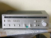
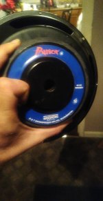
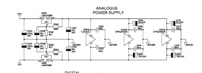
So, I got a CD150 on my bench, it looks nice and clean, doesn't look very used at all, so I think it's worth restoring and modding. Laser tests out fine (eye pattern is 1,5Vpp and laser is adjusted to 55mV) and player came to me working intermittently, that is, losing track very often, especially on CD-R. Measured voltages, all normal.

I decided to clean first, obviously, laser lens and lubricate hall motor bearing. No change. Then, installed new caps on servo board first. Especially the infamous axial blue Philips cap seemed to me a possibility. But, although there was an improvement (reading CD-R better), it still lost track sometimes (especially when trying to change to a track further away). When it loses track (or is it focus? Is there a way to monitor some signal to see if focus is lost, for example? FE Lag signal? Shall I scope that?), it makes a noise (swing arm beating against limit) and stops spinning, showing Err on display. One single time, it also showed Err 18. But I can't get an error code list anywhere for this player.

So, decided to recap most important caps on decoder board and display board, too (because I remember that there are some blue axial caps in and it contains the micrcontroller, so better go on the safe side).
It now seemed a little bit better, but still would easily stop when I would try to advance to a further away track (forward or backward).

Decided to try service program - would easily go to service position 3 and, strange enough, swing arm can be moved freely all the way without ever losing track (focus?) once. I mean, I tried really a lot, and it would never happen, only, obviously if I exceeded the end of the disc (btw, what happens is very similar to the intermittent problem while track changing). But the noise the swing arm makes when I command it back and forth in this service position, it's different from the noise it makes when it loses track while changing track manually in normal operation. Let me explain: in service position 3, it moves in 64 steps according to SM (you can hear that). When normal operation and I tell it to advance, say, 5 tracks, it makes like a sweeping, almost singing sound until it arrives and then seems to "lock in" and then starts playing. In the even of losing track, the same happens, except that close to the end of the movement, the singing gets deeper in sound and then it loses its position and bangs against the limit, disc stops and shows Err.
Strangely enough sometimes it works well and even manages to travel from track 1 to 20 and later back to 1, for example, without failure, several times in a row.

I don't have any CDM-2 based player here at the moment (the RAFOC is CDM-4), so I can't compare: is it normal for them to "sing" while the swing arm is moved further away during changing track manually? CDM-4 based players usually don't do this, for what I know, or just a little. Could this be some kind of parasitic oscillation of the radial servo? I mean, the easiest way to make the intermittent problem happen is when doing search forward or backward, first, it moves in steps like in service position (no singing sound), then it advances more, starts to sing here (and normally not loses track), but as soon as it advances very quickly, there it often loses track after some seconds. There, the sound is stronger and deeper.

To eliminate mechanical failures, I disassembled the whole RAFOC, cleaned and lubricated, nothing looked wrong, also cleaned the inner laser lens of the pickup.
What is strange with this behavior, is that it hasn't failed reading TOC once.
Or starting to play when press Play, never fails.

Tomorrow I will try to let it play alone a few discs from start to end to see if it fails on its own or if this only happens when we change the track.

Any ideas?

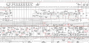
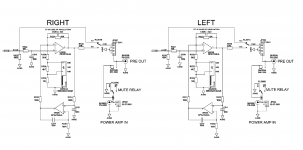
P.S: I might have found something by mere chance: in SM for another philips player based on CDM-4, it says as explanation for one of the errors: No TL pulse received within 0,5 sec during track jumping. Check the RE Lag circuit (Error during Search or Next/Previous).
This one sounds exactly like what is happening with this player! When I find some time, I will try to measure the TL signal. I'll also check the RE lag circuitry, which is explained in the SM, I think I'm onto something here.

Thoughts on my (almost) fully 3D printed midbass project.

Been working on this project on the back burner for some months now, ever since seeing this cool video on fully 3D printed enclosures.

These are the images of my design, and hornresp parameters and predicted response curve.

The driver I'm using is the Tang Band W4-1720, the 3D printer im using is the Creality CR-10, and the filament is a basic PLA.

I am going to be printing both halfs and sticking them together using just epoxy, and covering the sides of the speaker with ~5mm clear acrylic, using screws and epoxy to hold it down, I will be printing a speaker cover, too, and screwing the driver directly into the enclosure. I'm planning to use 3 layer walls with slight over extrusion, and just 20% infill with a large over extrusion to add physical damping.

The design should give me decent response from 60-200Hz, and I will be using this with a STR-DB870, if that has any bearing on the design.

Are there any newbie errors I've made so far? I also saw somewhere in a thread of filling in the body of a design using sand, to increase damping, thoughts on this? In this case I would still use a little infill to support the top layer when printing, and pour in sand while printing.

Should take 6 days to print both sides, so I don't really want to leave much up to chance and to remake this will take a lot of time and filament.

Yes I know this probably isn't going to get the most out of my driver, yes I know this isn't a very cheap way of making an enclosure, just for fun, and to use my 3D printer 🙂

Thankyou for any responses!

First One Large amplifier modules - still for sale, but will also consider a swap

Still for sale, but I would consider a swap as I'd rather not have these modules sat there doing nothing - and they do work perfectly well!

Feel free to make suggestions on what you'd like to swap - something you have might interest me, small speakers, power supplies, other amplifiers etc...

Link for the earlier sale:First One Large amplifier modules

Cd cutting out on loud and drum bits

Hi All,
I'm modding a Philips CD753 for a friend - I've done one before with no issues. I've removed the opamp section and will replace it with a lampizator valve stage. At the moment the voltage out DAC is directly connected to my amp. All I have done so far is to put separate 7805 regs to the three sections of the DAC, replace the rectifier diodes with fast recovery and the smoothing caps with better quality ones of the same value. The regulators are working correctly and there is no fluctuation in supply when playing. In the video on the link, you can hear the first 35 seconds of sound are fine then the drums come in and the scope flatlines. All previous testing was done with a folky album so the problem didn't show.
http://picklethedog.com/cd.mp4


Thanks guys

Listening session Infineon / TPA3251 / TAS3251

Having the TAS3251 board operationnal (NeatAmp), I wondered how it would compare to some other known amplifiers. As a reminder, the TAS3251 is an integrated chip that bring together a TPA3251, a "high-performance Burr-Brown™ DAC" and a DSP. The Input is I2S. The interface between the power part and the DAC is balanced. In my understanding, the best of TI engineers integrated in one chip.

I took the opportunity of a trip to Lyon to liaise with Daniboun, to meet him and compare to its current amplifiers: an Infineo amp and a Aiyima Tilear 2.1 TPA3151 with ELNA caps / OPA1656.

The Infineo amp was connected to an external DAC.
The Aiyima Tilear 2.1 TPA3151 was used with its bluetooth input.
The TAS3251 was fed by a small PCM2706 USB to I2S board (and a basic LED brick before receiving the expected Meanwell 36V 350W power supply).
This maked that the sources were different for the 3 amps.

We listened mainly to Jazz vocals, some drums performance, and some other tracks. We had not so much time available. So we got some first understanding but were not in a position to extensively compare each of the 3 amps with reference tracks. The switch over from one amp to the other, especially with my TAS3251, so we were far fom A/B blind tests. Last, I had not brought my test music, interested in discovering different tracks from Daniboun. It was not my best idea. I really liked the music we listened, for sure, but when you don't know the speakers, have different sources and use different music, you lack some landmarks to associate what you hear to the different components and the sound material. I take precautions about the context because sessions like this are not science, are very subjective, and personnal taste matters a lot in findings, that have to be taken with caution.

All that said, the three amps don't sound the same. I'm bad with analyses and wording my feelings, but here is what I would say.

The Infineon amp is the one we listened the less. For me it had a soundstage more "blurred" than the 2 others. Voice was "larger", taking more space between the 2 speakers. Overal restitution was nice, dynamic with some harmonic richness/warmth. Bus it was not feeling as natural as I would expect.

At the opposite, the TAS3251 NeatAmp had for me the most holographic soundstage. Sound looked to me very clean and neutral. After hearing the 2 other amps, it was as if "something" was removed. Like a Halo around voices and instruments. But maybe also possibly some harmonic richness/warmth. However, for me, this looked more natural. Daniboun pointed that he was less convinced by the basses.

The modded Aiyima Tilear 2.1 TPA3151 was sort of in between:
- Better soundstage than the Infineon, but less holographic than the TAS3251
- More richness/warmth/halo than the TAS3251 but less than the Infineon.

Bottom line:
- I was surprised that the TAS3251 NeatAmp was sounding (so) different than the modded Aiyima Tilear 2.1 TPA3151. They derive from the same familly of power chips. And they share dynamics, transparancy. But they definitly have different caracters,
- The TAS3251 NeatAmp is more to my personal taste with its soundstage and neutral/clean/natural sound. It is the type of caracter that minimize listening fatigue in my case,
- The level of performance you can squeeze from such amps allways seems to me incredible,
- Next time I will bring more of my test music to have more known references during the listening session.

Thanks a lot to Daniboun for the invitation, making me discover his speakers and current amplifiers (fast rotation), his music. It was a really pleasent moment !

Hafler DH-220, Bias and DC offset - need practical experience help

I have an all original Hafler DH-220. Its in great shape, and was dormant for 10+ years. Both channels are fine, and run the same temp, about 108F ± a degree. The DC offset had crept up from 15-20 mV to near 30mV over the past year.

I know about basic electronics and some troubleshooting, and usually have no issues with good instructions, but I don't know much about circuits or design etc.

Checking / adjusting the bias and DC offset are well described in the manual, but some additional practical experience would be helpful. I am turning the upper pot to adjust the DC offset. I only have one MM so I check one channel at a time.

When I turn the amp on, after the initial surge the bias starts around 275mA. The bias always creeps up to around 285mA after 15-20 seconds and to around 295 after a minute. It was still climbing, but very slowly. I am not sure if this is normal or not. If it is, how long do you leave the amp on? How long until it settles? After turning the amp off and letting the values drop to around 0.2mA, if I power it on again, it starts around 285mA. If I disconnect the leads after it drops to around 0.2mA and put the fuse in place briefly, when I reconnect things and power it up, it starts at 275mA.

How long does it take for the offset to settle? Are both channel offsets "connected" in their offset since it is a common ground amp? Do I need two MM's? It seems like once I adjust one side, the other changes. If I leave the amp on, and come back in 20-30min the values have also changed.

4 Sale - various DAC related boards, psu, kits, etc.

Have a few interesting DAC related components to offer up...

1. $45 - Completed Subbu 5v PSU capable of 250mA. Normally used with Subbu v3 DAC, but can be used with something else.


IMG_3049.jpg

2. $SOLD - Acko AKL-S03-BB Re-clocking board. I'll include the Potato Semi Flip Flop chips necessary for build. You'll need to supply the rest of the parts. Parts list and guide will be included.


IMG_5068.jpg

3. $25 - Acko AKL AMN-S02 and AKX302 clock board - this combo provides galvanic isolation and synchronous re-clocking with the Amanero USB transport and feeds i2s to your choice of DAC. S02 board has i2s isolation chip already installed. U.FL adapter board is included to add flexibility. Parts list and guide will also be included.


IMG_5070.jpg

4. $80 - Acko BBB-I2S/DSD - Beaglebone Black U.FL adapter and power management board. This board enables feasible synchronous re-clocking with Acko S03 or S02 re-clocking boards in DSD or i2s formats. If you want pictured Beaglebone Black tack on $50.


IMG_5069.jpg


5. $40 - Joe Audiophile BAL - SE KIT - this kit has all the parts that are needed and can be used in conjunction with the NTD1 to procure single ended audio. Also can be used with any other DAC that is balanced audio only.


IMG_4373.jpg

FS: Curryman USB DAC

So after being my workhorse for the better part of 4 or so years it's time to offer this one up.


This is a Curryman DAC... look it up on DIYaudio. This project was done when the ESS ES9023 and JG Filter Buffer were all the rage. It's a really good sounding DAC with the filter buffer added into the mix.

Some things to note:
• AMANERO USB
• Acko S02 re-clocking and galvanic isolation.
• AMB Sigma 25 linear PSUs.
• Talema trafos
• Switch on back to swap between Pre Filter/Buffer and Post Filter/Buffer.

I think all said this is worth $250 shipped or make me a fair offer.


IMG_5079.jpg

IMG_5080.jpg

IMG_5077.jpg

Replacement indicator Lamps

I have this amp apart recapping it and don't really want to go back in there for a really long time so am replacing the indicator lamps but cannot find a voltage or current rating in the service manual parts list. By the attached schematic I'm assuming that they need to be 5v? Any foreseeable problems if I use led's?

Attachments

  • new bulbs.PNG
    new bulbs.PNG
    444 KB · Views: 120

Fixed bias potentiometer

This is a practical question🙂 The potentiometer that I am using in a fixed bias supply is very "touchy", that is to say it requires a lot of fiddling and patience to get the value needed. I am worried that it may go out of adjustment as very little effort is required to turn the wiper🙁 I am sure I have seen pots that have a nut that locks the shaft but can't seem to find any on Mouser🙁 Alternatively I have read that Loctite 425 can prevent rotation but the resistance can be broken with moderate effort, only problem is that it is expensive🙁 Any ideas or help would be greatly appreciated🙂

WTT Diamond Audio D7104 ,Orion Hcca 225 series 2, and 2 10" Patriot si subs old schoo

WTT Diamond Audio D7104 ,Orion Hcca 225 series 2, and 2 10" Patriot si subs old schoo

They both work the D7104 is tough to find it's individually numbered and was a limited edition 4 channels. The legendary 225 is ready to go as well and will not disappoint. The 10" Patriot si subs are rare they have carbon fiber cones and we're made 1994 350rms 500 max I'd like to either trade for 2 12s more spl related higher end only stuff please there is other things I'm interested in really as well just shoot me an offer if even maybe sell them. I do know what they go for usually. Other amps welcome too. I will sell 10s they are like new and heard they are little beasts back then. Let me know what your offering take care.

Attachments

  • IMG_20201107_100728_01.jpg
    IMG_20201107_100728_01.jpg
    639.7 KB · Views: 65
  • USER_SCOPED_TEMP_DATA_MSGR_PHOTO_FOR_UPLOAD_1604902246251_6731447911061244064.jpeg
    USER_SCOPED_TEMP_DATA_MSGR_PHOTO_FOR_UPLOAD_1604902246251_6731447911061244064.jpeg
    112.3 KB · Views: 68
  • USER_SCOPED_TEMP_DATA_MSGR_PHOTO_FOR_UPLOAD_1604902306410_6731448163387828821.jpeg
    USER_SCOPED_TEMP_DATA_MSGR_PHOTO_FOR_UPLOAD_1604902306410_6731448163387828821.jpeg
    155.6 KB · Views: 57
  • USER_SCOPED_TEMP_DATA_MSGR_PHOTO_FOR_UPLOAD_1604805762465_6731043228730370880.jpeg
    USER_SCOPED_TEMP_DATA_MSGR_PHOTO_FOR_UPLOAD_1604805762465_6731043228730370880.jpeg
    115.4 KB · Views: 61
  • USER_SCOPED_TEMP_DATA_MSGR_PHOTO_FOR_UPLOAD_1604805699775_6731042965789594124.jpeg
    USER_SCOPED_TEMP_DATA_MSGR_PHOTO_FOR_UPLOAD_1604805699775_6731042965789594124.jpeg
    124.3 KB · Views: 64
  • USER_SCOPED_TEMP_DATA_MSGR_PHOTO_FOR_UPLOAD_1604805718074_6731043042544578451.jpeg
    USER_SCOPED_TEMP_DATA_MSGR_PHOTO_FOR_UPLOAD_1604805718074_6731043042544578451.jpeg
    145.3 KB · Views: 58

Active Preamp Section: Replaced OPA2134UA - Crackle sounds

Hello All,

I'm trying to fix the active preamp stage of a creek destiny integrated amplifier. I've replaced both opa2134ua opamps and the surrounding electrolytic capacitors. I checked all leads, my soldering work, and for any shorts in the capacitors and resistors. I can't figure out why I'm hearing crackling and suppressed audio in both tracks. It sounds like music is underwater + cracking noises on the beats. But I can hear some of the music. The issue doesn't happen when I've turned off the active preamp (gain switch) The only thing I can think of is a "fit to oscillation" note in the schematics. I've attached the sections covering the active stage. The passive preamp sounds fine and I have no issues with the amp stage. If I'm reading the schematic correctly the tl072cd opamp is part of the passive stage, right? Any help would be greatly appreciated.

Attachments

  • Screen Shot 2020-11-10 at 11.53.39 PM.png
    Screen Shot 2020-11-10 at 11.53.39 PM.png
    49.1 KB · Views: 190
  • Screen Shot 2020-11-10 at 11.53.25 PM.png
    Screen Shot 2020-11-10 at 11.53.25 PM.png
    125.2 KB · Views: 193
  • Screen Shot 2020-11-10 at 11.51.14 PM.png
    Screen Shot 2020-11-10 at 11.51.14 PM.png
    48.6 KB · Views: 192

Technics SA-GX190 Receiver issue

Hi!, i dont know if here is the right place to post, but any help would be very appreciated. I got a Technics SA-GX190 "Control Stereo Receiver" all in one with dual stereo amp, a friend gave me to fix it, aestethically is looking pretty good, functionally...well... sometimes works and sometimes doesnt, i managed to get everything working again, found bad relays, many cold solders..etc, except the receiver part... when you turn on sometimes you don't get any station on all bands FM/AM/MW but when you turn off it few times again i can get it working back.

Here are the symptoms in a more detailed view:
- noise after dialing stations when it was working, sometimes no sound at all
- noise after disconnecting and putting back the antenna
- silence after putting my hand close to the circuit board, probably because of interference
- the noise sometimes varies on volume, and after some time the stations
come back with a fading effect

The receiver circuit is a modular board

My guess is a faulty PLL, it uses a synthetizer chip for dialing the stations commanded by a microcontroller on the front panel, because sometimes the stations are innacurate/wrong despite what shows on the front panel

fortunatelly i found a schematic of the SA-GX170 model which is identical i'll post here

any help would be really appreciated since my friend will pay me good if i get it fully working 😀... thanks in advance

Does turning amp on and off repeatedly cause damage?

Hi All,


Apologies for the long post, but I was wondering anyone's thoughts:

I have a TSE-II with 300b tubes that I recently completed (or so I thought). It has about 40 hours of use on the bench, and maybe 10 since being finished up in its case, with no issues.

Last night, I had it on the bench as I was trying to troubleshoot some hum in my phono preamp (and DIY PH14 from tubes4hifi). I had the preamp outputs plugged into the SE, either nothing on the preamp inputs, or just RCA cables connected to nothing, and the speakers hooked up to the SE.

I was trying shortening and moving cables in the preamp, and was repeatedly turning everything on and off. Probably like a minute or so in-between on and off. Doing stuff like turning on the SE, then turning on the Preamp, waiting for the hum / tube hiss to come up, turning everything off, adjusting, and then repeat.

After a while I blew a fuse in the SE, which has never happened before. This happened during startup the SE had been on for maybe 5 seconds and as I hit the preamp on it blew. The rectifier glowed at the same time, so it took me a while to figure out it was the fuse and not the 5AR4.

With fuse #2, I started up, and after about 5 seconds a hum/buzz came out of the speakers, crackling sound, and then fuse blown. At this point I thought maybe it was the 5AR4 after all, so I switched it out.

With fuse #3, I started up, after maybe 2-3 seconds a bit of lightning in *all* the tubes at the same time, no sound from the speakers, and dead.

I have found the other threads about fuses blowing so I will get started on troubleshooting, but my two questions for now are:

1) Does it sound like I destroyed anything serious?

2) Is it a coincidence that this happened when it did? Or did I stress the amp by turning it on and off repeatedly?

Heavy duty speaker output switcher

My brother wants to switch two amplifiers between two sets of speakers, so I designed a circuit for him to do just that. You can find it at the github site


GitHub - profdc9/SuperSpeakerSwitcher: A heavy duty switch between two audio amplifiers and two sets of speakers.


Two channels are switched. Two 16 A relays are used to minimize contact resistance and allow for 32 A total continuous speaker current per channel. Both sides of the PCB are used for the connections to minimize trace resistance. The speakers connect using quick connect terminals to the PCB. The control is using a 12 volt remote enable signal that needs to source at least 2 mA. The PCB is powered by a 12 V wall wart that needs 1 A output.

Attachments

  • Board.jpg
    Board.jpg
    330.8 KB · Views: 98

Equalizer APO and its high pass filters

I downloaded this program and played a little with it, listening to music on my bluetooth speakers that have 10 cm midwoofers that dig to 70 hz at best.
I noticed when applying a high pass filters at 42 hz that the bass performance is dramatically improved , it sounds like bass boosted actually. Is that result of relieving small woofers from low bass duty or just those filters create a bass hump above cutoff frequency ?

Australian Electronics Enthusiast Required - apply within!

Hi all,

In typical fashin, UPS and the other carriers responsible have delivered a Bigbottle Phonostage to a guy in Ballarat, Victoria and managed to make it no longer function on one channel.

The owner is not that technically minded, so my instructions are going to waste.

Obviously i am happy to have the unit back and get it fixed but the shipping from Australia is mega bucks....then it's got to go back.

Is there anyone in his area that would be willing to have a look at it for Andy, the owner of said unit?

We don't expect your time to be free, but it would make life a lot easier for him if i could find someone in his area who isn't trying to charge him $300ph!

Please PM if you can lend a hand

NOS Seas Millenium Tweeters, Excel 5 inch, Morel MDT33, Peerless 830500

Hi
Posting this on behalf of a friend who is wrestling with some health issues.

He has quite a few new, unused, drivers held as spare stock for his main speakers, including:

PEERLESS 12inch 830500 long throw bass.
W15CY001 SEAS Millennium 5 inch with magnesium cone,
SEAS Millennium tweeter T25CF002
MOREL MDT33 Tweeter

He had put an ebay listing up, item 303627775948 where you can see the drivers available but it's not the clearest! Will have to get him to change that when he has a chance at some point. Hence me posting here.

So to clarify - there you can see the speakers and drivers but what is on offer are new, unused spare stock.

For now, please go via ebay, but if there is sufficient interest I will see if I can get quantities from him and post here once he has some respite from hospital visits.

Many thanks,
cv
Projects by fanatics, for fanatics
Get answers and advice for everyone wanting to learn the art of audio.
Join the Community
507,760
Members
7,887,261
Messages

Filter

Forum Statistics

Threads
406,173
Messages
7,887,261
Members
507,760
Latest member
The Fink