FS: Parallel-86 amplifier boards

I do not need them anymore, have built them for an active speaker system. Still use a pair of these amplifiers in my stereo setup.

280 € incl. EU shipping for the pair of Parallel-86 PCBs
(I guess that is what I have paid for the Bulk foil resistors only)

PSU with 4 x 10.000 uf Nichicon KG capacitors, 35€ each

Attachments

  • PAR-86.jpg
    PAR-86.jpg
    154.6 KB · Views: 168
  • PAR-86_back.jpg
    PAR-86_back.jpg
    132.5 KB · Views: 173

Help :) Trio Kenwood TK-88

I bought a Trio-Kenwood TK-88 model amplifier.
1 channel repaired and replaced power transistors with 2n3055.
This channel gets very hot and doesn't work properly.
I can't find the original transistors 2sd46 these transistors. I want to replace all of the output transistors. I want to portray this old 1967 old man. Which transistors should I choose instead of 2sd46.

Attachments

What are the actual differences in the Faital Pro 12PR3X0 drivers?

Looking for a way to add phono to an opus dual mono DAC...

Hey!

Ten years ago I was looking for a kit to give me balanced output from USB, and someone pointed me at the OPUS and I had a great time soldering it together and got a dual mono balanced DAC that has been humming happily away for a decade. So, cheers for that! I am actually going to make a second one for a raspberry pi, the onboard sound on those things is disgusting.

Anyway... I recently started to play some more vinyl, I have so far been just kludging together something awful with a Behringer USB RIAA card to get the audio to the speakers. However it sounds terrible and makes me sad.

So then I came to the twisted pear website and saw they have a lovely RIAA stage. I have two questions I hope someone can help me with,

1. High or low impedance? I am using a Grado cartridge, which all seem to be MI, which is more like a MM cartridge. Is the low impedance better for MM then?!

2. I suppose the Retro will have two balanced outputs, that I will solder onto XLR plugs and then plug the OPUS out when I want phono and back in when I want USB. But is there some kind of machine that Twisted pear audio makes that would allow me to input a pair of balanced inputs and then press a button or twist a knob or something that would send one of the inputs to the balanced outputs?

I understand I am describing a preamp, and I think vaguely that the Joshu tree thing is a preamp, but when I read the description it feels like a big volume controller, and I am not good at electronics. I just like nice sound 🙂

Any help with either of these questions would be very appreciated!

Thanks!

Apogee PSX-100 stopped syncing...

Hi All,
My beloved Apogee PSX-100 gradually began to stop synchronizing when using the digital IO and now will no longer lock no matter what. I contacted Apogee asking to repair it and without even attempting to help they said they won't even look at it because they can't get parts. BS.

I've got it open and it's a mess of 74 series logic circuits that is going to be a pain to trace. Although I'm motivated to do so, I just wanted to see if any one has repaired one of these OR a similar product doing the same thing? Any ideas of how to approach this to save some time/effort?

That said, I'm well versed in a lot of areas of audio electronics including embedded, just not digital audio circuitry (low jitter clocks, formats, etc) but I'm positive I can learn it. Is there a book or something on the subject anyone can recommend?

Because what I'm considering, if it turns out an FGPA has failed or something and it really can't be repaired, is to just redesign the digital IO section from scratch. The AD/DA boards are still working fine afaik, and I love the sound of the unit, why not make a DIY project out of it and potentially make it better?

Any other ideas? Hope everyone is staying safe!

Transformer with 2 separate 220V-windings on primary s.? (tube amp power-transformer)

Hi,


out of a box with random used parts I got a power transformer (for tube amps I suppose because of 6.3V secondary) with 4 pins on primary side, each manually labelled as "220V". Only one of these 220V labels also says "primary" and these two 220V-labellings seem to be visually seperated by a manually drawn line. Their resistances differ: between primary-called pins are 21Ω measured, the other ones show 86Ω. There is no connection in between, so there seem to be two separate windings on primary side.


(second side: 6.3V, 17V, 130V, 180V)


Are you guys familiar with such power transformers in amplifiers? Am I supposed to connect both to the 220V-grid (parallely each or treat like 2x110V: connect serially by bridging the windings to a single one)? Or is the second one actually an output winding (...like an isolating-transformer-feature)?


Thank you!


Poppy

Maida Regulator PCB

A while back I had some Maida regulator PCBs made and mounted the power parts on a large heatsink and ran wires to the PCB. I didn't like it. It was difficult to work on. I learned my lesson.

I whipped this one up with the idea that I could mount the LM317 and pass device on the heatsink and bend the leads upward to go through the board which greatly simplifies assembly.

There are provisions to stuff an LM337 and make a negative Maida. Board dimensions are 1.325" x 3".

Does anyone have any suggestions for improvement? I'm thinking I might get this fab'd soon, are there others that are interested in a group buy?

Questions regarding two load lines

In this thread I combine several questions I have regarding two designs, this to reduce the number of threads I start. Looking forward to your reactions!

1) Making a load line for 2xel34 in p-p class ab for a Marshall plexi I got the following result( picture 1). Notice how the load line enters the 25W max dissipation curve. I assume the max dissipation curve is for class A and I can average it for p-p.

Does this mean that I can effectively double the max dissipation curve to 50W in p-p since the tube is only there half a cycle? If so, what would happen when also paralleling tubes?

2)I am also trying to design a cathode follower. The load line is shown in picture 2.
The cathode can swing from 72-0 = 72Vp-p
Input voltage swings from 172-254= 82Vp-p
I am trying to find the center bias point.

Would this be half cathode swing or half input voltage swing?

3)Picture 3 is the schematic. For the AC load line I need to calculate Rac.

If I take the output at C1 is this R3 || Rload?
If I take the output at C2 is this R2+R3 || Rload?

4)Output impedance of cathode follower
If I take the output at C1 is this: output impedance 12ax7+R2||18K?
If I take the output at C2 is this: output impedance 12ax7||18K?

Many questions, thank you in advance.

Attachments

  • Plexi Load Line.JPG
    Plexi Load Line.JPG
    64.5 KB · Views: 131
  • Load line 12ax7 18K CF.jpg
    Load line 12ax7 18K CF.jpg
    341.5 KB · Views: 115
  • 18K Cathode Follower.JPG
    18K Cathode Follower.JPG
    31.3 KB · Views: 144

Metal Pushbutton Switch with Latching Action - 30 pcs - SCHURTER

Selling 30 high quality switches

Made in Switzerland by SCHURTER

These are perfect for use in devices as the main ON/OFF switch.

- SPST
- off-on (latching)
- drill diameter 19 mm (or 19,1 mm; provides an easier fit)
- 12A (AC/DC)
- 30VDC, 250VAC

These buttons are brand new, and come in original packaging.
3 boxes of 10 pieces each

I could actually sell 35 if necessary .. 30 can go for sure.

Current new price is € 18 + VAT, or $ 21.50.

Package deal € 295 for all 30 (€ 9,83 /pc)

Can be sold on invoice, in that case 21% VAT will be added unless you have a valid VAT number.
No VAT for sales outside of Europe.

Attachments

  • 20200910_151702.jpg
    20200910_151702.jpg
    355.7 KB · Views: 233
  • 20200910_151707.jpg
    20200910_151707.jpg
    262.2 KB · Views: 236
  • 20200910_151710.jpg
    20200910_151710.jpg
    290.7 KB · Views: 231
  • 20200910_151726.jpg
    20200910_151726.jpg
    342.8 KB · Views: 228
  • 20200910_151822.jpg
    20200910_151822.jpg
    181.5 KB · Views: 238
  • 20200910_151831.jpg
    20200910_151831.jpg
    182.9 KB · Views: 180

Sparkler Audio S507 CD player

Just in now!


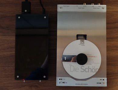
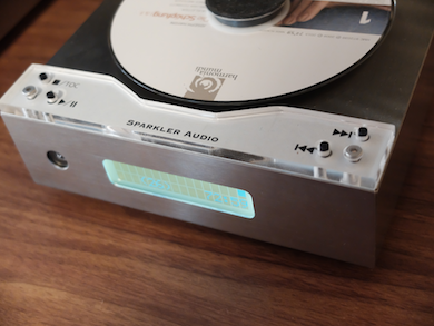
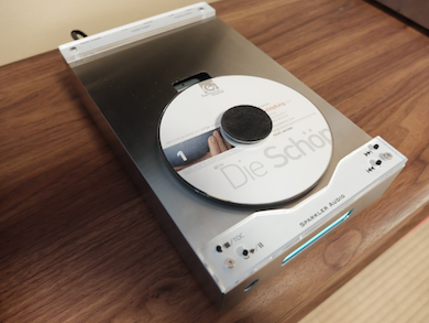
S507 top loading mechanism-like analog CD players

Inheriting the sound quality of the model S303A "notebook CD Player", this new model also has a non-oversampling D/A converter built in at a minimal size, and is finished as an integrated CD player.

From our investigations, we successfully improved the technology to further reduce the noise level, enhancing the fine expressive power. S507 is compatible as a high-end CD transport, where two digital output types (S/PDIF, I2S) are supported: CD transport type (S507t) with or without built-in DAC. As for the built-in DAC models, there are two types of signal modes available: conventional voltage-mode (S507v) and a new approach current-mode (S507i). Once you listen to the sound quality of current-mode (S507i), you will never forget the sound quality!

How does the voltage-mode and the current-mode work?

By adopting superior current-mode signaling in exchanging audio signals, dramatic progress is made from the conventional audio system to significantly improve the purity of the sound quality.

To use current-mode type (S507i), you need a current-mode amplifier, such as S502i and S505i.


https://s25.postimg.cc/a2t60wf7j/S507_large.png[/img


CD Transport Common Specifications (S507t/S507v/S507i)

S507t Transport $1,290.00
S507v Voltage mode CD player with DAC $1,475.00
S507i Current mode CD player with DAC $1,575.00


- Power Supply: Worldwide, depend on market (IEC 3 pin AC inlet), AC110~120V, AC220~240V (factory assembled)
- Mechanism: Top loading mechanism
- Disc Format: CD-DA, CD-DA format CD-R/CD-RW, CD layer of SA-CD (SA-CD, HD-CD is not supported)
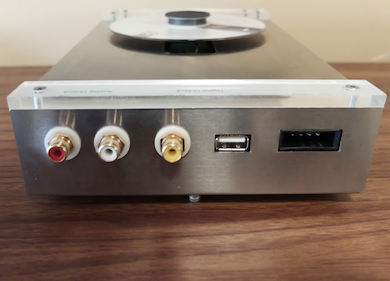
- Digital Output 1: S/PDIF (coaxial) x1 (isolated ground), 75Ω, 0.5Vpp
- Digital Output 2: I2S (BCLK/LRCK/DATA/GND) x1, 3.3V TTL compatible logic level, USB 'A' type connector
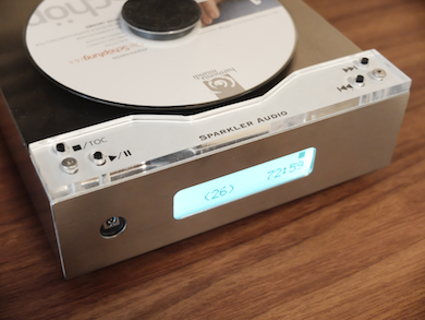
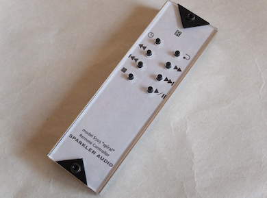
- Operations: Top panel tact buttons, remote controller
- Playbacks: stop, play/pause, previous/next, fast reverse/forward playback (x10), timecode (elapsed/remain, track/disc), repeat (track/disc) CD Drive Unit: Size W150×H45×D240mm
- MoESKINE® large notebook -- Weight 1.2kg
- Power Supply Unit: Size W100×H45×D200mm ible size, Weight 1.0kg (without power cable)
- Materials: Stainless steel, hairline finished. Power supply unit has gray-smoke acrylic top panel.
- Accessories: power supply unit, power cable for IEC 3 pin AC inlet, disc clamp, remote controller, user's manual
- Built-in DAC Specifications (S507v/S507i)
- Both internal and external DC power supply available. φ2.1mm DC jack o connect with such as 12V battery.
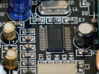
- DAC: Philips TDA1543 16 bit non-oversampling DACRe-clock: Fully discrete analog oscillator (ultra-low jitter, ultra-low 1/f phase noise)
- Crystal: Professional grade quartz crystal (frequency drift is less than 5..7ppm)
- Output Stage: Fully discrete BJT current mirror amplifier
- S/N ratio: 96dB (typ)
- Line Output (voltage-mode): Analog RCA pin jack (unbalanced) max - 2.2Vrms (0dB), L/R stereo x1
- Line output (current-mode): unbalanced RCA pin jack 5.5mAp-p, able to connect to 0Ω devices


Linear power supply conversion advise

linear power supply convert - Google Photos

Hi, Its my first post here, so please be gentle. As an introduction Im not new to electronics, but my knowledge and experience is pretty limited.

I have a acquired a Chinese linear power supply(photos within link) that currently kicks out 12v with adjustment for 1v either side via the blue pot.

this psu has two psus within the box and id ideally like one to push out 5v and the other 9v, but i could live with both being 5v.

Would this be easy to convert and what options would i have?

thanks for your time
Darren

Advice upgrading capacitors on streamer

Hi guys,

Greetings from Portugal.
First of all, let me tell you I'm no expert in electronics. Just an enthusiast.
I have a Cambridge Audio 851N streamer and I'm thinking about replacing the electrolitic capacitors to improve performance.
The stock capacitors are from NOVER, an unknown brand to me.
In the audio path I'm thinking about upgrading to the ELNA Silmic II.

But for power I really don't what to go for.

1.
Power on the audio board. 8x Nover RX 35V, 2200uF capacitors next to 2 L7815 voltage regulators.


Option 1 - Replace these Nover low ESR for Panasonic FR, also low ESR with same voltage and capacity.

Option 2 - Replace with same voltage 35V but with higher filtering capacity (ex:3300uF. If so, which capacitors should I go for?

Power supply. 3x Fujicon RK 35V 2200uF (standard capacitors for general purpose)


Should I also increase the filtering here? Also, any recommendations?

All help is much appreciated.
Thank you.

Andre

Mordaunt Short MS10

Bit of a long shot. I am looking to get some older speakers to try out various tweaks. One of the speakers I was looking at is the Mordaunt Short MS10. Well rated in it's day. My question concerns the fact that there are 2 versions, quite distinct. One has a smaller round main driver, the other has a squared driver, which was popular with various makers (JPW Sonata driver looks the same.) Has anyone heard the smaller driver version. They come up for sale, but I cannot find any reference to them. Please note this is not about the MS10i in it's various guises.

Rare Snell Type 1 - Broken Tweeter

I have a pair of these excellent speakers.

After years of enjoyment, the right tweeter gave up.

Wire from the voice coil to the negative post is broken, but I also cannot get continuity across the voice coil. Damn!

There are no markings to identify this tweeter (just like the 10" woofer).

The front plate is 90 x 110mm and the voice coil is about 1.25"

The mounting holes are 9cm x 7cm.

Any recommendations on a repair service?

Thanks,
Dan

Attachments

  • IMG_1392.jpg
    IMG_1392.jpg
    493.2 KB · Views: 737
  • IMG_1396.jpg
    IMG_1396.jpg
    662 KB · Views: 487
  • IMG_1395.jpg
    IMG_1395.jpg
    489.5 KB · Views: 464
  • IMG_1393.jpg
    IMG_1393.jpg
    695.1 KB · Views: 464

Mini wire stripper for working inside the chassis?

Hello guys,

I do have a couple of full-size wire strippers, but they are not very convenient for confined spaces.

Sometimes, when you're trying to be really neat with your build, the best way (for me at least) is to solder one end of the wire in place, lay out the wire inside the chassis and then trim it to fit precisely. Then you try to strip the other end, and that's where the problems arise.

I'd like to have the smaller tool for this job. I'm thinking of something with the size of, say, Leatherman Squirt ES4 (I do have PS4 and I don't need another multitool though), capable of dealing with 16-18AWG down to 24-26AWG (and preferably cheaper than the Leatherman).

Any suggestions?
Thanks!

Advice on checking Transformer

Hi,

Firstly, please cut me some slack, the internals of hi fi kit is not my normal playground, but I do like problem solving, and I'm trying to keep my mind active during lockdown, AND before anyone says it, I am fully aware of the dangers of electricity and do not go beyond what I consider safe.

I have a fondness for Cambridge Azur 640h hi fi servers and have bought a few on Ebay to repair with reasonable success. They are basically a mini pc with a quality cd drive and proprietary software. Anyway one of them i'm playing with can't even get past first base and I don't seem to be getting power though to the motherboard.

So, my question....the power supply unit is a toroidal transformer which I'd like to try and check. It has the option for 240 or 110 volts. The transformer has marked up on it what the primary and secondary cable colours and voltages are, but they all have 3 cores! So the primary is identified as 115v/60hz and 230v/50hz, the cores are brown, blue and black. Can I assume that brown and black is 110 volt input and blue and black is 240 volt input (or vice versa).

Also again, there are three secondary outputs (16v, 15v and 7v) One is a twin connector. but the other two are 3 cable - green yellow green and white blue white. Which should I connect across to check the voltage...and why three?

Thanks

Alchad

Out of the Box: Part 6, a 25W PP UL 6L6GC Monoblock

I built two of these in the early 60s. They were in constant use for more than 15 years until I bought a Sansui AU-717 / TU-717 Combo.

On the shelf for many years I replaced the coupling caps a few years ago. Both still operate OK.

That is an HP67 programmable in front from 1975. I used it this morning.🙂

Attachments

  • 25W Amp Front 10W E.jpg
    25W Amp Front 10W E.jpg
    125.3 KB · Views: 595
  • 25W Amp Bottom 10W E.jpg
    25W Amp Bottom 10W E.jpg
    110.1 KB · Views: 580

Sony Thump

I have a sony tc rx70es cassette deck, one thing is puzzling me, when i swich the deck on at the mains there is a loud thump through the speakers, ie deck itself is off and amp which is on, is working through another input, it could be any eg cd or aux not the selection for the tape deck, a friend pointed me in the direction of the line mute circuit in the tape deck, could he be correct.

Output stage CFP to EF on LJM amp?

I have a couple of LJM L12-2 that I would like to play around with, and try EF output stage instead of CFP.
I don't have the spice model for the 12-2, so I used one I found for the MX50SE, which is very similar, but only has one output pair.

Basic simulation seems ok, but before going ahead and soldering, I thought I would check with the experts 🙂

There are two things that I have been thinking about:

-compensation/stability, should probably be re-tuned?
-Current through drivers seems to give little chance in distortion FFT. What would be general advice/considerations for choosing the resistor between drivers?

Attachments

  • image.jpg
    image.jpg
    50.3 KB · Views: 689
  • mx50ef.jpg
    mx50ef.jpg
    163.5 KB · Views: 692

Remote control for Bow technologies wazoo

Hi I need help .... I have a Bow Technologies integrated wazoo model and I don't have the remote control which at the time was too expensive and was not purchased.
I had thought considering that the integrated already includes a wireless receiver associated with a motorized alps that perhaps someone had found something that could control it (only volume up/down with a programmable universal remote control).
Of course you could make an internal modification using the motorized alphs ... but for the moment I would like to try to leave it original.
Thanks to those who want to help me.

Joseph.

c'mon guys, lets put our heads together to control a STA310 ac3 decoder

Looking at the datasheet of the STA310, controling it via i2c looks no more difficult that desining an mp3 player with an STA013. I want to design a surround sound DAC, with S/PDIF input, and 3 CS43122 D/A converters on the 3 i2s outputs. I want to use a uC an 8 bit 8051 uC from either phillips or ST Micro. I only know assembly, not c. Datasheet can be found here. Let's put our heads together. This won't be too difficult.

Question 6p3p*2 Class A valve amp - put the wrong valves in - it's broken...

Hi there

I'm new to this forum and a bit of a newb at repair so please be kind!

I have a class A valve amp bought from ebay based on the 6p3p and 6N1 valves. I believe it was based on a kit from SiliconRay and I bought it from UK ebay prebuild.

Is siliconray still here? 🙂

Here is a video and here is the thread that seems to be authoritative for the kit.

The circuit diagram is there in the thread, though apparently there was a second version of the circuit as I recently saw another ebay listing mentioning this.

Long story short, I had a small problem with the amp and was wary of running an amp randomly built on ebay so I gave it to my local hi-fi shop for an expensive once over. They fixed all problems and suggested I only use the 4 ohm taps on the back of the amp for all speakers. It worked fine for some weeks.

Never one to do the sensible thing, I read that the amp is working with KT66 somewhere (not true) so I tried a couple of JJ KT66 in place of the 6p3p. The amp sounded better for a while but soon broke at high volume (as high as 5-8w class A gets anyway) with a little smoke from inside. Since then I have kept it and it's been retired - I've put a lot of money into it so I am loathe to chuck it.

I want to repair this amp and get it working again with the 6p3p valves or perhaps modify it to use KT66 which is apparently quite simple. I have had a look at it and there are no obviously burnt components or smoky bits on the inside. The circuit diagram is available in the linked thread (hopefully)...

... if I figure out how to modify the amp for KT66 maybe these will be the same components to swap out as those that failed already. I'm quite the newb though I can solder and I'm hoping to learn amp repair and valve amp repair in particular.

I can add pictures if that helps. When I gave it to the shop I'm not sure if they massively changed the amp from the original siliconray spec but I hope not. (the shop tech was quite vocal about how unsafe the amp was before he fixed it up!). It looks quite simple inside. I would like to have it as a backup or perhaps swap it into the main system for a change once in a while.

Any suggestions? Maybe which caps to check and replace and how to do so? Maybe not caps? How would this amp be modified for KT66 and would that likely be the fix if this is all that happened so far?

Thanks
Zoea / N

What are these?

Hi,
while investigating my stashes I found these three devices that I had pulled from 1970ies equipment a long time ago. The designation of the left handed one is barely visible, but clearly shows INTERSIL as the manufacturer. The one in the middle and the right handed ones show AN 122 as the designator. They've got six pins, arranged in two groups of three each. Searching through the WWW didn't help to define them, most probably 'cause they're obsolete for a very long time. Does anyone know what I have here?
Best regards!

Attachments

  • 20200501_174314_kl.jpg
    20200501_174314_kl.jpg
    90.7 KB · Views: 294

6J1 biasing inconsistencies with datasheet

Dear all,

this is my first post here. Welcome everybody 🙂

I recently bought a Little Bear P5-1 preamp and was not happy with it (due to several reasons like cheap components, hum, power supply operated outside its specifications etc.).

So I thought that I will build my own "Big Bear" with the tubes from the Little Bear, which are chinese 6J1 (compatible types: 5654, 6AK5, EF95).

I already build the power supply, which provides +- 32V (-> 64V) and +12V for the heaters (DC -> please no discussion about that, I want it like this 🙂).

I drew a 10k load line in the "triode connected plate characteristics" in a graph of a 5654 tube (this one: http://6bm8-lab.fr/phpBB/download/file.php?id=41 which is from the Raytheon Manufacturing Company datasheet). The line goes from ~64V to ~6.4 mA.

I want the operating point to be at 1.8mA on the -1V grid line. So the cathode bias resistor should be 1V/1.8mA = 556 Ohm.

I started to play with the tubes on a breadboard building a "common cathode" circuit (the tube is connected as triode). The circuit is like this:

- 10k anode resistor connected to +32V
- 100k g1 (grid) resistor connected to -32V
- g2 connected to anode
- g3 is internally connected to cathode
- for my experiments I connected the cathode in various ways:
1. directly to -32V
2. with a 470 Ohm resistor to -32V
3. with a 1K resistor to -32V

If the cathode is directly connected to -32V then I get a anode plate voltage of ~38V and a current through the anode resistor of 2.6mA.

With a 470 Ohm resistor, I measured 0.75V across this resistor which corresponds to 1.6mA current through it.

With a 1k resistor I measured 1.1V and 1.1mA (52.9V at anode -> 0.95mA through the anode resistor).

-> So with increasing cathode resistor the voltage drop gets higher and the current lower. At 1.8mA I would have less than 0.75V and at 1V, I would have more than 0.95mA but less than 1.6mA (I guess around ~1.1mA).

First question: With the latter measurement I get approx. my -1V bias, but I was wondering why is the resistor value so far away from the theoretically calculated 556 Ohm? Further, ~1.8mA should flow through the plate, but I only calculated 0.95mA. This seems too far away from the datasheet.
BTW: I tried three different 6J1 tubes with similar results.

Second question: Should I set the bias such that a current according to the datasheet (1.8mA) is flowing to set my desired operating point or such that there is a certain voltage drop (-1V) at the cathode resistor? In any case if I cannot rely on the datasheet and the calculated resistor, then I have to use a pot and adjust it to my desired bias, right?

Third question: In the datasheet is written G2 and G3 connected to plate. How is this possible? The tube has an internal connection from G3 to the cathode. How can it be connected to plate without creating a short circuit?

Sorry for these "stupid" questions. Hope that someone can answer my questions.

Thanks!

Klaus

Matching different voltage transformers that are close

I have two transformers salvaged from broken amplifiers. I have plans to build some Chinese kit knockoffs. Building a dual mono with no plans on any form of bridging. One is 27-0-27 and the other is 30-0-30 according to my meter when connected to the mains. I was wondering if I should use some diodes to lower the voltage of the higher to get it in the same level as the other one. Like a second bridge rectifier in series. Don’t think it has to be perfect. Looking for better ideas or confirmation that my idea is ok.

Thanks.

Sunfire TGR-401 repair help needed

Hello all
I picked up a Sunfire Theater Grand TGR-401 that needs service. Plugged in, power off the receiver makes a horrible vibrating/buzzing sound. Based on where I think the sound is coming from it is a speaker output relay. If anyone has experienced something similar? Confirmation would help before taking things apart. Flannery does not work on 401's as they were released after his departure from Sunfire.
Thank you

Yet another ABX box!

Hey folks!

I've seen several great ABX box projects on here already, but not one which was quite what I was looking for, so I thought I'd make my own, and make the design available as open source.

I thought I'd post the process along the way here in case any good feedback pops up 😀

Goals:
  • Switching headphone-level signals
  • Relatively inexpensive
  • 3.5mm TRS jack inputs / output
  • Simple push-button operation
  • LEDs for status indication
  • Operate from 9V battery
  • Draw power only while a button is pressed (good battery life)
  • Latching relays
  • PCB design and Arduino firmware published on github (MIT license)
  • Gerber files published for public use (order your own PCB's)
  • Accessible to everyone: through-hole / easy to solder parts, Arduino Nano as drop-in processor, easy to program via USB.
  • KISS!

Haven't thought too much about case options, but it will likely be a hammond cast aluminum stop box, or an aluminum extrusion, possibly with PCB endplates.

Non-goals:
  • Switching amp-level / speaker-level signals
  • "Money is no object" components / design

Functional description
  • Physical inputs X and Y are mapped to conceptual inputs A and B, but this mapping is hidden from the user.
  • User interface: 3 buttons (Re-roll, Switch, Reveal) and 4 LED's (X, Y, A, B).
  • Each momentary button connects power to the circuit / Arduino. Power is drawn from the battery only while a button is depressed.
  • Each button also connects power to a unique Arduino pin which identifies the function to the Arduino (8V_REROLL, 8V_REVEAL, 8V_SWITCH).
  • "Re-roll" button: randomly decide a new X/Y to A/B mapping (stored in EEPROM), disconnect the output relay, switch the input and dummy relays several times in a manner which maintains the secrecy of the mapping, reconnect the output relay, illuminate the initial selection ("A") LED (which remains lit until the button is released).
  • "Switch" button: switch from input A to input B or vice versa, then illuminate the "A" or "B" LED (which remains lit until the button is released). The switch selection is stored in EEPROM.
  • "Reveal" button: A pair of LED's is illuminated which reveals the secret mapping to the user (one of A&X, A&Y, B&X, or B&Y).

Relay operation
  • Left, Right and Return signal lines each have two relays in series
  • The output relay is disconnected first,
  • ...then the input relay is switched,
  • ...then the output relay is reconnected.

I have a basic schematic drawn up (attached), and I thought I'd post here before drawing up the PCB, in case anyone has any good suggestions! 😉

Attachments

Pearl Phono R1 Voltage question

I am trying to diagnose a persistent but intermittent problem in the right channel that drops out. What should the voltage be between C11 and R24? I measure some voltage on the channel that works, but none whatsoever on the right channel. All the voltages on the test points in the Fig. 5 schematic are correct and moving upstream from C11 I also don't find any differences. The difference appears at C11 and R24. Thanks.

Boombox concept feedback

I would like to build a portable boombox with components I have on hand and am looking for pointers and suggestions.

I am a farmer and our farm had a big aiwa bluetooth speaker that played loud until it didn't. I have a bunch of hamfisted farm hands and want to build a portable speaker that can play loud and last a full day on a charge. I intend to mount this box on a stripped pressure washer cart. would be easy to mount a passive radiator in the down firing position.

I have

Soundstream D100 Amp
Soundstream D60 amp
2ea Dayton Dc160-8 6.5" woofers
2ea Tang Band 1320sj 4" drivers also 8 ohm
2 Dayton DC28F-8 1 1/8" silk tweeters

I like the idea of adding a passive radiator, but not familiar with which product. I like the idea of adding an active crossover so as to simplify the number of components stuffed into he box. I figure the tweeters could be dropped with minimal affect on the sound since the TB's play so nicely up high. A 16" by 21" box will fit nicely on the deck of the sprayer frame and I can go as high as needed upto 30".

I am open to using a head unit or a simple blue tooth receiver. I am unfamiliar with what battery and charger I should be looking for this project.

I am an experienced woodworker cabinet maker, have a full shop. I have wired 3phase machines and micro power controls, audio I am very inexperienced outside attending directed electronics snake pit course some 15 years ago.

All feedback is appreciated.

Reducing thump

OK, huge turn on thump due to active crossovers being single rail power and 10uF coupling caps. Amp does not have a muting relay. I know the obvious solution is to add a relay either to the amp output or preamp output.

But, is it a reasonable approach to reduce the issue to start with by carefully selecting the output coupling cap?

For instance, my sub plate is 20K input. So rather than the 10uF electrolytic, I could drop in a 1uF giving a 8 Hz first order filter and 1/10th the DC energy stored. Same token on my main amp, 33K in, so a .22uF gives me a 20 Hz roll off for way less DC charge. ( Plus removing electrolytics from the path which is trivial but basically good)

Somewhere; Self, Cordell, Didden, Pass, someone much smarter than I had a reason not do do so, but I can't find the reference.

b2 6000w

Hi,
I have an issue with a repair,
I been told the amp works pretty good at cold winter days and not very good at summertime.
The issue is that it after a while of playing it cuts into protect, then starts working again, to be in protect again, and it goes faster frequency after the first time.
its been checked by a man referred from b2 to repair, without finding any fault.
I just checking if any encounter this problem before.
I was suspecting the ntc resistors but i used a heat gun and multimeter and the resistance goes down with increased heat. both side seems to be alike.
Any ide where to start ?
psu board, comparator circuit ? or bad MOSFET that heats more then others ?
best regards
Niklas.

Attachments

  • b2 amp 6k.jpg
    b2 amp 6k.jpg
    867 KB · Views: 129
  • b2 amp1 6k.jpg
    b2 amp1 6k.jpg
    770.3 KB · Views: 109

Search problem "GaN transistor"

I saw the thread
http://www.diyaudio.com/forums/powe...or-replacement-sic-rectifier.html#post5348261
and wanted to be informed of these semiconductors.

The search for "GaN transistor" in parentheses turns out with no result:
"Sorry - no matches. Please try some different terms. "

Search without parentheses is useless. But as you see in the thread title
the phrase was used in the forum. "GaN" alone will give no result either.

What is going on ? Thanks.


PS "SiC transistor" search works ..

Balanced preamp

I have a Pro Ject RPM 1.3 turntable that will be over 30' from my AV rack, and I have a Music Fidelity phono preamp that will be next to the turntable. I cannot run balanced from the turntable as the table has RCAs.

Question: I prefer to spend under $500 for a balanced preamp (I could go up a bit more). I have looked on Ebay and see a lot of clones (MBL and Levinson JC2), but I am not sure if all balanced preamps with XLR, and RCA jacks will convert the unbalanced to balanced audio( I say this because my Music Fidelity phono preamp will not convert). I also would prefer to not lose any audio quality with the preamp. Do I need to spend more, and buy a non clone preamp?

Will a passive balanced preamp be able to drive such a long run?

SUT for Denon DL-103R

I would like to build an SUT for my Denon DL-103R.

According to Theanalogdept website the Cinemag CMQEE 3440A with a step-up ratio of 1:35.4 should be a very good match-up but with the Denon DL-103 [.3mV].


However, the output voltage of the 103R is 0.25mV. Will 0.05mV make a difference?

The 103R has a 14 Ohm internal impedance which is quite different to the standard 103's 40 Ohms.


Cheers,

Mic29752 resistors help

hi guys, i need some help. i am building a power supply for a mini pc based on this mic29752 regulator. what is not clear to me is how to choose the resistance values ​​to get the desired output voltage. I would use a 15V transformer to get about 21V in to the regulator and I would like to go out with about 20V. there are infinite combinations to obtain this value, for example r1 = 1000ohm and r2 = 70ohm, but also r1 = 200ohm and r2 = 13ohm etc ... can you explain to me? thanks!

Accordi to datasheet: Vout=1,240 x (1+R1/R2)

Gotham Audio GAC-4/1 XLR Cables: $10 each

Heard of this cable? Curious about it? It is extraordinarily good. Ignore the price. I've used it exclusively in my system for about fifteen years, which is almost all Pass electronics. Before the Gotham, I had Audioquest Lapis (then top of the line) and then cables from FMS (a legendary cable here in New England). I don't have to tell you why I switched. I recently sent some to a friend who has the best system I've ever heard (outside a store) and who has very expensive cable from a very famous name. His response: "I need more of this wire".


If that's not enough, Pass Labs used Gotham Cable to connect the two halves of their $16,500 XP-30 pre-amp when it was used in mono. I'm guessing they didn't do it to cut costs.

I have three pairs of balanced interconnects built from Gotham Audio GAC-4/1 "star quad" microphone cable and Neutrik XLR connectors that need a new home. I'm selling them for less than the price of the connectors: $10 a pair. You couldn't build them yourself for less. I have two 2ft pairs and a 3ft pair. Easy way to try out this cable and see for yourself. Then you can buy the wire and make some yourself.

Shipping should be no more than $8.30 (in the US): Small flat rate box. We can probably do it for less.

Hi from Dallas

Hi all,

I've been a long time lurker and have a little experience tinkering with guitars and guitar amps, as well as building handheld Nintendo 64s and other oddball projects. Just now looking to put together a decent phono stage, amp, speaker setup and figured it time to join the forum.

I'll post my projects as they come along, just making an introduction here and thanks in advance to the helpful forum members.

Brett

Help! I connected a sub to my '87 Yamaha RX-700 & now keeps shutting off and on!

I've had this receiver since my high school days... it has been my trusty workhorse for over 30 years, and now I've gone and done something I don't know how to undo!

Recently I picked up a Polk Audio PSW505 powered subwoofer. Since this receiver has no "sub-out" connection in back but does have A and speaker B outputs, I tried hooking up the sub using the two channel speaker option, per the sub's owner's manual (attached photo) but using "front" speakers only, since I don't have rear speakers.

After setting this up, the stereo started shutting itself off within a few seconds of trying to play music. When I powered it on, it would shut off again.

So then I disconnected the sub and went back to my earlier configuration, just using the R/L speaker A connections, and the problem persists. Only now, it shuts itself off after a few seconds of play time, then shuts back on again, etc.

What have I done to my beloved old receiver?
Any suggestions to remedy the situation?

Thanks in advance!

Rear Panel - Yamaha RX-700U Owner's Manual [Page 8] | ManualsLib

Eric
An externally hosted image should be here but it was not working when we last tested it.

idle adjustment jumper cables Pioneer SA-508

Dear all,
In most Pioneer vintage amps the idle adjustment is set by two jumper cables. If it measures too low you're supposed to cut the jumper cables. See picture for an example.


I'd like to replace these jumper cables with a trimmer to precisely adjust it. Which type of trimmer would be suitable? How many Ohms and how to solder in the leads (three leads seem to be the standard)? Thanks in advance for your advice.

Attachments

  • jumper cables.jpg
    jumper cables.jpg
    764.3 KB · Views: 103

AB763-ish Bogen CHB35A rebuild

Okay. So. I still haven't finished my "top caps" project, and I have a 6DY7-based hifi project waiting behind that. But I spent the last week out of town and away from my stuff, so I started noodling on the next guitar amp project.

Donor is an early 70s Bogen CHB-35A. Original tube complement is 6EU7, 12AX7, 6C4 concertina PI, and a pair of 7868s in AB1. So let's see ... five triodes and a push-pull output section ... sounds like a one-channel AB763, if I do the reverb in solid state and eschew the tremolo. I've even got a pair of matching 1x12 cabinets that came as part of the complete PA.

The basic plan is to reuse the iron, chassis, and sockets. I recently bought some 6P41S tubes, so those can go in the power amp. I've also got a bunch of 6N2Ps, which make fine 12AX7 substitutes. Add a 6AV6 to go in the 7-pin socket and we've got everything we need.

I adapted Robrob's one-channel AB763. Notable changes:
  • Reverb has been replaced with a simple BTDR-2 circuit. More on that.
  • Power supply is very different. The donor uses a voltage doubler and a capacitor-coupled bias supply, so I pretty much had to stick with those. The 6P41S has very low screen voltage specs, so I'm pulling them from the 1/2 B+ point on the doubler. It also needs -65V bias, dang. And I'm omitting the choke in favor of an extra RC filter.
  • No tremolo.
  • 6N2P for phase inversion (as opposed to 12AT7). I like the hotter sound of a 12AX7 in the PI in BF Fenders.

Other than those things, depending on your perspective, it's either a Super Reverb with diode rectification, or a Bandmaster with reverb added. The preamp is pure AB763.

About the reverb ... I found a lot of conflicting information about how best to make use of the BTDR built-in to a circuit. I took the simplest approach I could: A voltage divider to attenuate down to its 1.5V limit, an LND150 source follower to handle the low input impedance, and a voltage divider network to get the signal back to the mixer tube. HOWEVER, I know this circuit isn't right. I would appreciate any thoughts y'all might have.

I'm copping out on the 5V power supply for the reverb and using a USB wall-wart, with some additional filtering.

vy1m6zu.png

Cascoded DN2540 CCS down to 0.3 mA

Hi everyone.

I built the circuit several times using DN2540, and tried several different ones, and I can get down to 0.3 mA. No problem. Using different JFETs as the bottom device too.

I've read many times that a cascoded depletion mosfet CCS can be problematic if the Vgs of the top device is not large enough, as it limits Vds of the bottom device, and that limitis the minimum current that can be achieved.

Was I just lucky?

I just measured about -2.5V for the top device Vgs on one of those circuits I still have around, while set for around 0.4 mA.

Need newb help with Arduino Due

I'm looking to add an arduino to control my dac. I'm not worried so much about writing code as that's already done and proven to work for others. This whole platform is new to me. I can see that the initial scrpt or program is the .ino file and that will contain commands as well as references to libraries but I'm not sure how to put this altogether in Arduino IDE to upload it to the Arduino Due.


I purchased this display for the project
5"TFT Display Arduino Touch Shield w/SSD1963 Library for Mega/Due


There is a download with examples in it here
https://www.buydisplay.com/arduino/Libraries-Examples_ER-TFTM050-4.zip


I want to test the 480x272 demo. I see the ino file and have downloaded the UTFT library and added it to Arduino IDE.


Do I open the ino file in sketch then include the UTFT library and complile then upload? Or am I missing steps?

slot loaded open baffle?

Inspired by this
The Slot Loaded Open Baffle Project Article By Nelson Pass
I am phantasizing about a floor to ceiling slot loaded open baffle using 10 Tymphany XXLS-300F50AL01-04 per side.
As a little exercise I experimented a bit with slot loading on my Beyma 15BR100 U-shaped open baffles.

Thight fit, but moveable with rubber mallet


Anyone done the same, what are your perceptions?
I conclude with Pass'...there is gain, also I would say "attack" and "faster". On the negative a bit of change in tone, the mellow and effortless of true open baffle has changed to a bit of "hollow" and yes...boxiness. The cool thing is how easy it is to experiment 🙂

Help with selecting a woofer for a 2 way enclosure ?

Hi everyone. I got a nice deal on some speaker boxes.
For a around 15$ i got two nice beefy speaker boxes with a nice paint job and woodwork. Anyway boxes are 24 cm wide by 50 cm high and 39 cm deep and have 14.7 cm cutout for woofer ( i think it is for 6.5") and 8 cm for tweeter and 9 cm hole for flared bass reflex tube...
They are made of 18mm MDF with a decent amount of bracing and feel super solid like a solid block of concrete lol. I think that volume is around 1 ft3 or around 30l. Calculations are not 100% accurate they are just approximated.
The first driver I was thinking of was a visaton w 170 s but I don't know how it would work in 2 way... And I want a hi fi sound but this visaton driver seems like it is more aimed towards low bass rather than quality bass
Second one I looked at is really expensive one compared to visaton but it also seems like it would fit in 1 ft3 enclosure. It is a tang band w6-1721. It seems nice but that is a lot of money to waste if it doesn't work out.
I was also looking at Dayton audio drivers but they require much smaller enclosure.
I want nice warm and punchy bass and mid-range rather then muddy low bass. Sorry for the wall of text and thanks in advance.
Here is a video of one of the boxes...

speaker boxes. - YouTube

Aikido / Buffer

Unfortunately, I find very little information about Aikido, as an output stage for the DAC (directly to the power amplifier), which I would like to build in balanced version and which has an impedance < 100 Ohm at the output, so to speak in buffer function. I found a table (attached) in the Broskie documents, in which some constellations appear, which make this possible. But approximately only with 9-pin tubes. For octal tubes, which I would like to use, only the type 6AS7 is to be found (B+ 100V), which however is accompanied by a very high current (Ik 100mA).

Can anyone tell me if there is a range of values that makes it possible to use octal tubes? With: B+ of 150V, lower Ik value and Zo < 100 Ohm. Otherwise I have to start with Noval tubes. But again, I can't find any values that would meet the requirement.

Does anyone have a tip?

Attachments

For sale or swap: TI and BurrBrown audio op-amps, drivers, power amps....

TI

LME49710HA (TO-99, metal can)......5USD
LME49713HA (TO-99, metal can)......5USD
LME49720HA (TO-99, metal can)......5USD
LME49990MA (8L-SOIC)..................2USD

LME49600TS (KTT)......4USD
LME49810TB (TB-15).....7USD
LME49811TB (TB-15).....7USD
LME49830TB (TB-15).....7USD
LM4702BTA (TO220-15)........7USD

LM4780TA (TO220-27).......8USD
LM4781TA (TO220-27).......8USD
LM3875TF (TO220-11).......6USD
LM4765T (TA-15A).....6USD

BurrBrown

OPA549T (60V, 8/10A POWER AMP).....7USD
OPA548T (60V, 3/5A POWER AMP).....5USD
OPA547T (60V, 500mA POWER AMP).....3USD

PGA2310PA, PGA2311P,PGA2320I, PGA4311U...( Digital valume)....4USD

All the stuff is 100% genuine, from manufacturer, looks like mostly obsolete by now. I can send it worldwide for 6€, as long it can be send as regular letter, in bubble wrap protective envelope. Payment via PayPal or bank transfer. Will also be glad to swap for something that interest me, mostly PCBs for above listed components...Make me an offer..

Regards

Feixiang FX-98s PCM2704 + XR1075 +QS7779 USB DAC

This thread is to discuss everything about the Feixiang FX-98s PCM2704 USB DAC, including reviews, upgrades, mods, problems, troubleshooting, etc.

The FX98s is a budget USB DAC with a Burr-Brown PCM2704 DAC, XR1075 BBE, QS7779 Virtual Surround decoder, surround, bass, treble and volume controls, straight-through line amplifier (line in to line out) and headphone amplifier - all in a compact extruded aluminium chassis with good finish and production values.

It is upgrade friendly in a few areas - electrolytics and opamps, which are generally the only things that need upgrades, if at all. The pics below show the board and a few upgrades that I performed - the only upgrades that are really required are the opamps (2x NE5532 upgraded to LT1208 and LT1364) and C8, the analog regulated voltage bypass for the PCM2704 (upgraded from Rubycon YXA to Rubycon Black Gate PK). I upgraded some additional electrolytics in the signal path to Nichicon Muse SW and Black Gate PK, though not strictly required for a first-level upgrade.

Attachments

  • fx98s_full_12x9.jpg
    fx98s_full_12x9.jpg
    347.3 KB · Views: 762
  • fx98s_pcm2704_12x9.jpg
    fx98s_pcm2704_12x9.jpg
    210.7 KB · Views: 718

Transformer with lower secondary voltage and two heater windings

I am looking for a transformer for my preamp project with a roughly 380 vct secondary but with both a 5 and 6.3 windings for heaters. Right now I have a Hammond 269ex which seems to be giving me the high output I need but only has one winding for heaters. I have been unable to find any transformer with both the 5 and 6.3 that has a vct under 400v. Does this exist?

Thanks.

Rega Planar 2 1978 motor mount screw size? M3 M3.5?

Hi, first post! I hope I've done this correctly (I wasn't sure how to format links, if that's a thing) and I couldn't see any threads about this already. 🙂

I've recently been gifted my father's original 1978 model Rega Planar 2 and when replacing the motor suspension belt I stripped the head of one of the screws which hold the motor in place.

I'd read [1] that I should be replacing them nylon M3 screws, so I ordered some to find out they're too small - the threads don't bite properly and the screw head does not fully cover the hole in the platter. So I ordered a set of M4 screws to find they're much too large and wont even fit in the hole.

I've messed up twice so I do another Google search and find people saying it should be a M3.5 screw [2]. However as far as I know M3.5 isn't actually a standard and there for screw options are more limited. After an eBay glance it looks like I'll have to get white flat heads or white bolts instead of the original style black philips head screws. It would annoy me if they don't match the original style but as they wont actually be visible during normal operation (only when the platter is removed) it's not the end of the world.

So before I continued Goldilocks-ing with M3.5 I thought I'd ask more knowledgable folks if I'm doing something wrong?


Can anyone confirm I should be using M3.5 or could the M3 have had a manufacturing defect (like they're actually M2.5)?

I've included an image of all the screws in question - M3, Original, M4. The original screw is in the middle and 5mm long, the replacements are 6mm long as I wanted them to be a little easier to screw in. You can see the M3 seems quite small, it does have a tighter thread pitch. The M4 and the original might have the same thread pitch, I'm not certain.


(These screws are plastic/nylon in case anyone didn't notice, if you overtighten they're meant to fail before you do damage to the motor mount)


[1] '80s Rega Planar 3 motor suspension screws | pink fish media
[2] old planar 3 refurb - motor mount screws- Vinyl Engine


Thanks for any advice! 🙂

Attachments

  • 20201112_182635.jpg
    20201112_182635.jpg
    337.5 KB · Views: 126

DIY XLR mic AB switch

Hello guys! New member here 🙂


I'm trying to build my own microphone AB switch. Something like this:


https://www.palmer-germany.com/en/products/signal-splitter-switcher/5114/abo
or
HotShot DM-1 - Radial Engineering


But both of them are specified only for use with dynamic microphones. I want to use it also with condenser mic but I can't figure out how to do the wiring so there are no pops because of the phantom power.


What it should have:
1 XLR input
2 XLR outputs
Should be able to be used with dynamic or condenser microphones (with phantom power)
Optional LED indicator of either channel


Is there anyone who has already tried something like this? Or someone who would be able to help me?


Any help will be much appreciated!


Thanks,
Honza.

Jantzen JA8008 alternatives

Troels tqwt is a speaker I would love to build one day. The problem is that once you add a shipping and the drivers and tax it is way out of my price range. Are there any more affordable alternatives available for this driver?

I was also wondering if someone could explain to me how Troels tunes the enclosure to increase the sensitivity of this driver as he mentions in the link below. I've never heard of this before and I thought sensitivity was solely a product of the driver(s) design and implementation. I.e. using two drivers in an mtm to increase sensitivity.

http://www.jantzen-audio.com/download/ja8008-tw034-kit/PD_JA8008_Aug10_v3.pdf

FS: Accurate Inverse RIAA Network

My implementation of the Inverse RIAA Network (IRN) for testing phono preamplifiers, based on the Andrew Russell article (November 2016, http://hifisonix.com/wordpress/wp-content/uploads/2016/12/Accurate-Inverse-RIAA.pdf). For MM and MC preamps. Surface mount resistors and capacitors (<=0.5% R, 1%C) for better than 0.025% accurate performance. Requires a signal generator with output impedance of 50 ohms or less for testing.
$30 includes shipping to CUS only.


11/16/2020 Unit is SOLD

PCB's are still available


For those who want to practice/improve surface mount parts soldering skills, I have (8) pcb’s available. Thirty eight 0805 part size resistors and capacitors are required. It’s not too difficult to do.
$5/board shipped to CUS only

PM if interested. Thanks.

Attachments

  • F416DEDF-660D-4D26-8B87-AC4CAB149D54.jpg
    F416DEDF-660D-4D26-8B87-AC4CAB149D54.jpg
    485 KB · Views: 192
  • 34CC8D64-F3F7-4254-B16B-D877D9D4E26E.jpg
    34CC8D64-F3F7-4254-B16B-D877D9D4E26E.jpg
    427.6 KB · Views: 196
  • 5D8F6613-1A4C-4C75-98C9-FB927854EBE0.jpeg
    5D8F6613-1A4C-4C75-98C9-FB927854EBE0.jpeg
    925.5 KB · Views: 190

Measuring LDO with passive/active notches/filter

Here ow the new "Measuring LDO with passive/active notches/filter", so that we no longer hijacking the "Low-distortion Audio-range Oscillator" thread.

Administrator please move last related to this one..

In other words the measure a LDO with passive components or using active components as with OPAMP's provides several challenges in terms of

. Notch Depth
. THD & Noise added given from the parts (R/C/OPAMP's)
. Noise alternations (reduced or amplified) in any form
. Harmonic's attenuation
. May consider balanced or none balanced use

..


Hp

RF impedance matching

Well, I did not know where to post this thread, if the moderators think there is a more appropriate place they are welcome to do so! 🙂

I would like to ask this: in what frequency range does impedance matching become important in order to avoid problems?

For example, I will try to pass a 2.5MHz square (or sawtooth, fast rising or falling edge anyway) to a small capacitor (50-100pF), but with lots of volts in amplitude (50-100). So I wondered:

Let's say I use an RF transformer to step the voltage up. There are 50 ohm transformers available for that purpose. But if I was to terminate the transformer properly, I would have to waste around 50Watts of power on these terminating resistors! 50-100Vpp into 50 Ohms should be something like that.

Then I wondered, what if I just hooked the transformer up and don't match impedances. Is my frequency high enough to encounter problems? A fast (20ns) falling or rising edge might hide frequencies up into 50-100MHz, so the spectrum is broader than 2.5MHz, and that got me into thinking.

And, sadly, I can barely find clear explanations around the web about how to proper match, and when to do so (frequency etc). If anyone knows a good place about all this I would be glad!

Capacitors and current limits

hi, can someone help me to clarify some doubts? I wanted to know the relationship between the capacitance of the filter capacitors after a rectifier bridge and the amount of maximum current that the rectifier diodes can accept. let me explain: I know that after the bridge, if the capacitance of the capacitors is too small there is too high a ripple, if instead it is too large, you can have a peak current at ignition that is too high which could damage the bridge. so given a certain voltage, what capacity to use ... what is an acceptable ripple (1v?)? (however using a downstream regulator)

Inductor de-soldered

Hello,

Some two years ago I built speakers and made a decision to wind inductors myself. Not the greatest speakers by any means, but they're mine.
About a month ago, they started to act weird, - the bass driver in one of the speakers started to sort of lose connection - like headphones with broken cable. After a week of this on-off issue nonsense, the other one gave up too! Thought maybe the amp is going (never doubting yourself, right?) but upon opening one of the speakers - I noticed that the inductor, which I soldered directly on the driver terminal has come off.
Funnily enough, the other speaker has the exact same issue.
So I have few ideas as to what could be the cause and hoping, anyone can rule out one or more.
1. I did a poor job of soldering the inductor to driver (If I'm allowed to say so, I know how to solder (but not too bright with electronics 😀 ), been doing it for a long time and am aware of how cold solder joints are made). But maybe the copper wire and enamel is playing a role here? I did clean it off and anything remaining should have burned off.
2. The inductor got hot enough to cause it to fail eventually.
3. My amp is pushing large current through terminals which cause excessive heat? (this is pure guess without any backing)

The inductor is 0.793mH - not sure what else is of importance, so please ask.

I did jump the gun and got a new amp working on a foolish assumption that the speakers were fine, and now I'm a bit hesitant to connect them to the new amp if I just solder back the inductors.

p.s. At the time I finished the speakers, I checked the resistance and everything looked exactly according to calculations.

Regards

Hypex FA123

Hi All,

I am about to order a pair of Hypex FA123 to implement DSP and drive my clone Klipsch La Scala.

I was planning to mount the plate on a wooden board, which in turn, would be fixed to the rear of the bass cabinet using spacers. I would likely put a closer at the top to stop the majority of settling dust getting to the plate, but leave it open on the sides and bottom to give adequate ventilation.

The manual shows that the unit has a mounting depth of 55mm, would I get away with using 60mm spacers or would that not be adequate to prove ventilation?

Thanks

After FH3 - Victor ...Next ?

I built a set of FH3 for my son last year , after that i built a set of Tabak W5-2143 for my wife's daughter ( really cool too )

as they work really great i was impressed ....
But my parents were also impressed and wanted as set of speakers

So i digged the forum for another speaker construction and decided to built a set of Victor (FE166 woden design )

Now the problem is my wife ( i know it's not a pb in fact 🙂 ) =

She says The FE166 Victor are nice and sound really good 😎

I'll go for a LB ( nearly 100% confident )
No matter WAF factor or money : What would you build ?


ps : at the moment my wife says " i love that " so no Waf issues for me 😀


201111092657333532.jpg
Projects by fanatics, for fanatics
Get answers and advice for everyone wanting to learn the art of audio.
Join the Community
507,758
Members
7,887,202
Messages

Filter

Forum Statistics

Threads
406,170
Messages
7,887,202
Members
507,758
Latest member
Cindy