[SUB] svs sb 1000 or create DIY one?

Hi Guys, I have got klipsch the sixes active monitors. There is a possibility to connect the subwoofer. I have decided to get one. There is no enough of bass for me especially in the movies.


Everyone is recommending: SVS SB 1000 which is like $500 price tag. My room is like 25m2.


Would be possible to create better subwoofer by myself in this budget?(500$)

It should be active. I have almost zero DIYAudio experience but I'm very open to gather some.

little help on my project?

Hi all
I did built a two way speaker using the monacor SPH13c as mid bass and a Monacor DT254 as Tw
I used a second order cross over (around 1800Hz) with an L pad on the TW
The speaker sound pretty good and over all I am happy with it but finally I get some (hobby) gear to measure the frequency response and also I learn a bit to use XSim
So simulating the system there is a few Db deep just at cross over frequency and this is confirmed by in room measurement .Nothing dramatic but it is there!(changing polarity on the TW make it much worse)
I just cannot avoid it. The only scenario I can simulate were the response is much better almost perfect is if i use the same L Pad and second order filter but moving the cross over point very low. Lets say 1.2K.
Now the Tw Fs is 900Hz so in theory it is possible but what are the implication of doing this?
Thank you for help🙂

One song, can't miss, demo to the non audiophile

Let's say you have a non-audiophile friend/neighbor whatever that stops by and they see your system and after the "what's all that" conversation you want to play something for them to get a glimpse of what a hi fi can do. You put them in "the chair" and you can play something that will really demonstrate what the system can do. What's the one track you would play? Say, something under 5 minutes long, that would appeal to someone who's a fan of music but has never really thought about a serious hi fi.

Right now I've been smitten with Sara Bareilles' Goodbye Yellow Brick Road, Live from Atlanta.

Driver Ic question

I’m working on a Taramps 8K the driver ic’s for the outputs are SI8244BB

I’ve included a data sheet for these .

Wondering if these voltages appear correct or am I missing some voltages ?

Amp will power up but no audio

Pin 1:3.55
Pin 2:0.00
Pin 3:5.00
Pin 4:0.00
Pin 5:0.00
Pin 6:1.19
Pin 7:0.00
Pin 8:5.00
Pin 9:0.00
Pin 10:0.00
Pin 11:12.80
Pin 12:0.00
Pin 13:0.00
Pin 14:10.33
Pin 15:10.33
Pin 16:12.39

Attachments

  • 668FC700-B096-4689-AB82-952E43413705.png
    668FC700-B096-4689-AB82-952E43413705.png
    638.7 KB · Views: 119

Kicker zr360

Good day gents,
Recently completed rebuilding the right channel and minor PS repair (FETs replacement only) in a kicker zr360.
On initial power up I get about 19v dc across the speaker terminals and it quickly settles to around 210mv (this is in bridge mode).
All other power ups after this there’s only the 210mv across the speaker terminals.
If I leave the amplifier disconnected and aside for a few hours, if I power up the amplifier it repeats this, it has about 19vdc across the speaker terminals which quickly settles and all other power ups after this it’s around the 200mv level (bridge mode).
Anyone ever came across this before?

Attachments

  • 44C79129-638E-4A46-9523-495BC59B457B.jpg
    44C79129-638E-4A46-9523-495BC59B457B.jpg
    1,021.6 KB · Views: 135

Misco-Bold North Audio

Bold North Audio Releases Two High Excursion 6.5" Woofers Employing XBL2 Technology | audioXpress

Thought this was interesting. Relatively reasonable pricing for high-end drivers. Tweeter doesn't look bad either. Assembled in Minnesota.

?world-class-performance-is-rooted-in-fundamental-scientific-research-and-the-love-of-music/

The 6.5" drivers share the same motor but have different moving parts. Xmax limits for the midbass model are similar to the Purifi.

Purifi Audio PTT6.5W04-01A 6.5 Inch Woofer Review

Beogram!

Found this in attic of the old house, has been up there for at least 30 years.

It is a B&O Beogram 1000 made around 1970. It was a gift from friend in back in the 80's, the arm had no counterweight, so I machined a new one. It was used for a short time, then put into storage after being replaced by a modern Japanese turntable.

When I found it again it was in a bad condition, filthy, dirty and rusty, but the motor was still running ok. It was taken apart, cleaned and the steel parts painted. Then reassembled, lubricated and adjusted, broken parts replaced. The hardest part was repairing and polishing the acrylic dust cover. It seems like the pickup is ok, but probably not as good as new. It plays ok for now anyway.

Here are som pictures of the restored Beogram, please enjoy.

Attachments

  • Beo34.JPG
    Beo34.JPG
    144.5 KB · Views: 263
  • Beo45.JPG
    Beo45.JPG
    116.7 KB · Views: 248
  • Beo44.JPG
    Beo44.JPG
    120.6 KB · Views: 253
  • Beo50.JPG
    Beo50.JPG
    116.1 KB · Views: 249
  • Beo51.JPG
    Beo51.JPG
    129.4 KB · Views: 252
  • Beo52.JPG
    Beo52.JPG
    124.4 KB · Views: 127
  • Beo53.JPG
    Beo53.JPG
    86.6 KB · Views: 119
  • Beo41.JPG
    Beo41.JPG
    93.6 KB · Views: 132

Best DIY Preamp II

I know there's an old topic about this Best DIY preamp, dating almost ten years ago, but I am very curious if there's new input on this subject?

I am considering solid state.

One of the preamps mentioned over there is PassDiy
The last changes on that site date from 15 years ago (there seems to be no more progress)

How does the DIY stuff on that site compare to the commercial stuff like for instance https://www.passlabs.com/products/xp-12/?

And what about the stuff sold over here versus the real stuff

Or what about this?

SB Acoustics Drivers TS Consistency 16 Months Apart???

Hi all,

I'm starting to think about expanding my current stereo subwoofer set up from one SB Acoustics 8" SB23MFCL45-4 in a 12L sealed cabinet per side to two sealed subs per side.

I bought the initial drivers 16 months ago and here's my query:

If I bought another two would they match the pair I have now? I have no idea on the long term consistency of TS parameters that come out of the factory.

My instincts lead me to think that there will not be that much difference and if I go ahead with this idea I should keep each pair together from their respective purchase date. However the asymmetry in my mind may drive me nuts.

What are peoples thoughts here?

Cheers!

Overload margin in Phono pre-amp

Hi all,

I'm designing a flat pre-amp to interface with my turntable (Pioneer PLX-1000 with an Audio-Technica AT-XP5 ). This is going to feed a TI PCM4222EVM which will feed a miniDSP openDRC-DI. RIAA and subsonic filtering will be done inside the DSP. My line level "preamp" is a Topping DX7pro feeding DIY active speakers.

The flat pre-amp will be based on the AD8429 chip, so setting gain is just a matter of putting in the right resistor value.

The AT-XP5 has an output of 5.5 mV (at 1 kHz, 5 cm/sec). So about 55mV @ 20KHz. If I set the gain of the AD8429 to 40dB that gives a maximum output of 5.5Vrms or 3.89Vpk. The AD8429 can ouput a maximum of about 13Vpk on +/-15VDC rails giving me a headroom of 9.12V. This is about 7.4dB headroom.

Is this enough or should I lower the gain of the AD8429 to increase the headroom and avoid clipping on pops / scratches? I would like as much gain in the first amp as possible to get the best possible noise performance.

Just for fun: a superreg with <12 discretes??! ?! ?

During a discussion about an add-on for upgrading 317/337 regulators, a question has surfaced:

Would it possible to design a "superreg" using only 12 components or less, preferably all discretes?

Here is an answer (to be taken with of pinch of salt, and in the spirit of Christmas magic, something that participants to the previous thread seem to have missed).

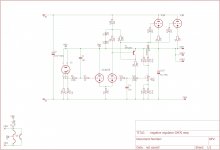
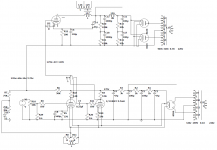
This example uses 11 discretes, and outperforms a cap-fitted 317 on all key parameters (without using any cap).
Does it qualify as a superreg?

Certainly not by today's standards, and the DC stability is approximate because of a crude, first-order temperature compensation, but the central question was noise-related, and it does not perform too poorly in this regard (and there is a lot of room for improvements, since the circuit is based on the <12 components constraint, and no cap).

May I remind everyone that this site is named DIYaudio, and members like to fiddle with creative, cheerful and unorthodox solutions (which is not synonymous with worthless), which is why I post this circuit.
Grinches, etc., please don't look further and move along....

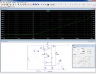
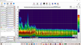
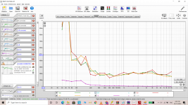
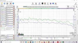
Here is the PSRR of the basic circuit: ~80dB

724106d1545600050-fun-superreg-12-discretes-suprpsrr-png


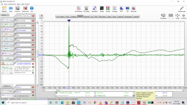
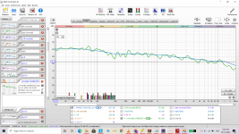
This is the output impedance: ~1.6mΩ

724107d1545600050-fun-superreg-12-discretes-suprzo-png


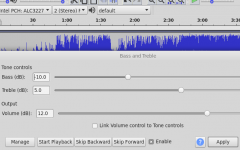
The measured noise, in a 10Hz to 10kHz bandwidth varies between ~2µV and 4µV, depending on the LED used and the error amplifier transistor.
The most favorable combination (I only made a limited number of tests) is an old Siemens green LED (CQ-something) and a BC337-40 resulting in ~2µV, and if the LED and transistor are from 6N139 coupler (an attractive solution because of the thermal tracking, the single component and the good temperature compensation), this becomes ~2.5µV.

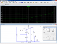
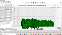
It is possible to compensate some of the parasitic parameters like Early effect to the first order by adding some tweaks.
The practical range of this type of tweak cannot exceed one order of magnitude, ~20dB: beyond, the adjustment become too sensitive to be of practical use, but for DIY applications, 20dB is realistic.
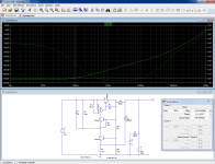
Here is the result with tweaks active (becomes >12 components, of course)/

724108d1545600050-fun-superreg-12-discretes-suprpsrt-png


724109d1545600050-fun-superreg-12-discretes-suprzot-png


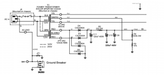
Note that R3 is not a physical component: it simply materializes the order of the components on the output track: R5 needs to be upstream of D1.


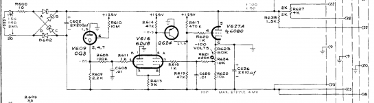
It is important to note that the circuit is not self-starting: this can be seen as an advantage or a drawback, depending on the application.
In a previous example, I have used this as a "feature".

Disclaimer:
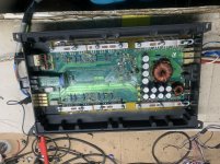
The circuit in its present condition is suboptimal in many respects: its main purpose is to deliver nice figures within the 11 discretes constraint, and although it works (I had to make actual measurements on the breadboarded version), I certainly do not recommend using it in its raw state.

It could become really useful with only cheap and minor amendments/additions, but it will probably remain unable to beat the best silicon $£€ can buy, made by the top foundries.

I will discuss later the practical adjustments required if the circuit has to be used in the real world, by people that do not necessarily have access to Farnell, Mouser, etc. and for whom a 317 is already a kind of luxury (2/3rd of the world population?)

Attachments

  • SupRpsrr.png
    SupRpsrr.png
    91.4 KB · Views: 4,022
  • SupRZo.png
    SupRZo.png
    91.4 KB · Views: 2,883
  • SupRpsrT.png
    SupRpsrT.png
    93.6 KB · Views: 2,875
  • SupRZoT.png
    SupRZoT.png
    89.3 KB · Views: 2,821

FS: Aurasound NS15-992-4A 15" Subwoofers x2

For Sale

Two used Aurasound NS15-992-4A 15" Subwoofers

Bought second hand but never used them. Tested recently and they work.
There are some scratches on the bottom and the gasket has some damage where it was stuck to the previous owner's enclosure.

Not sure how much people are willing to pay but I know they are quite rare and difficult to get hold of.

I'm in Surrey in the UK. Happy for people to collect or I can post. They are 22kg each so looking at £20 postage in the UK and would be very expensive to post out of the UK.

Offers please.

IMG-20200418-183047.jpg

IMG-20200418-183143.jpg

IMG-20200418-183151.jpg

IMG-20200418-183205.jpg

IMG-20200418-183222.jpg

IMG-20200418-183229.jpg

Magnequest DS 050/600 OPT replacement?

The subject OPT is employed in a line preamp with sum total one tube, a 5842 RF type. MQ is retired. I respectfully request a list of the best replacement transformers to build a matching preamp. I also need to know the cost for the replacement trafo.

Upon request I'll post the schematic which I sketched. The MQ DS 050/600 OPT has 3 output leads with 3 different gain options of about 8, 18 and 21 dB. A fixed gain of about 14-17 is OK for my application.

A couple days ago I asked MQ for the trafo specs and no reply yet.

PSU design target and "spectrum of harmonics" of ripples

I just read an interesting article about power supply design and would like to draw your attention to figure 6B and 6C.

Design Considerations - 2

The author describe the "spectrum of harmonics" from capacitor input and choke input filter is different, and that would affect the sound. I guess it is saying that the ripple does not only sound like 100/120hz hum but all different kinds of buzz/harsh at higher frequencies. I don't notice much elaboration on such view from the internet and the main focus on PSU design has usually been how much p-p ripple remains after filtering. Nevertheless I did noted a reply in a post in this forum that choke input sound "ease". That comment seems coherent to what the author suggests.

https://www.diyaudio.com/forums/tubes-valves/101064-motorboating-post1199057.html

What is your view or experience on choke-input filter on output stage / preamp / stage?

Looking for HA1452W Op-amp Replacement

Hi everyone, has anyone here done the HA1452W opamp swap with another device? I have a JVC A3 amp that has a dodgy phono stage and since every part checks out, only the op-amp is left, both channels have a hashy background but the right channel is much worse. All voltages are perfect, as are the caps, I pulled several and checked capacitance, replacing a couple that had corrosion on their legs. The Line stage is spot on.
I have three possible 14 pin options here, though since I now will have guests any moment, I haven't been able to check their circuit details. They are: AD713AN; TL074CN and an LM324N.
Would really prefer a drop in replacement if possible, but it's no biggie to alter any compensation caps.
Be grateful if anyone can help out here.

Tubelab Simple SE Blowing C3

Hello,
I've been enjoying my TSSE for a while (since 2009) and tonight I smell something is burning after using my amp for an hour.

When I detached the board from the case C3 was blown as well as the fuse.

What may be the cause of this? I can see from the schematic that C3 is part of the power supply. I believe upon visual inspection that no other part was involved.

Thanks for your time.

Punch 851s

Hi! I have a punch 851s, it comes with the lm317 shortcircuit. Replace it and again in short. Find d3 in short and replace it, im testing with a lm7815 for the moment.

I pull out all output mosfets, all are ok. Rail caps out of the board for test.

I have +- 47 volts on rail. -20v on 640 gates and +20 v on 9640 gates, so if i put one and one the ps shuts off, both are on at the same time.

The first problem with the lm317 in short was +47 volts instead of +20 volts on the control circuit. 4 47ohm resistors replaced because the high voltage. All 1am and 2a and 1q smd transistor are ok. Bias pots 2k ohm readings are ok. A56 and a06 ok.

I have the 800a2 schematic, are the same board.

Any ideas?

ads power plate 120 repair

Hello group,
I have an ADS power plate 120 with turn on problems. When turned on the power supply just has like a one second pulse, like burst or spike and the goes to zero volts, voltage does not go to high either. Not sure if the amplifier is in protection or power supply itself is bad. looks like it is a self oscillating power supply. any help greatly appreciated.

-150V regulator for fixed bias triode amps

I just finished a series regulator for amps that require a stiff negative supply. I have a couple friends building GM70 amplifiers and i thought this would be a welcome addition.


Ideally you would connect rectified and smoothed 230VAC to the inputs.


The schematic is based on the supply from the Tek567 tube O'scope


Pass tube is a 6080/6AS7 or pin equivalent.


The long tailed pair ECC88 runs into a PNP transistor VAS. This gives a large amount of amplification.


Any thoughts?


Once im happy about the boards i will post the gerbers for free in my gerbers thread.

Attachments

  • Schematic.PNG
    Schematic.PNG
    186.3 KB · Views: 440
  • schematic R0.0.jpg
    schematic R0.0.jpg
    431 KB · Views: 411
  • GM70 negative board image.png
    GM70 negative board image.png
    265.6 KB · Views: 428

Speaker characteristics- Oppisite of crisp?

With my very basic knowledge of speaker design, enough to fill a thimble I'm hoping to increase my terminology at least enough to describe speakers eloquently... After that some questions to expand my understanding of characteristics...

If you have a speaker that's detailed, crisp and accurate, could the opposite of that be considered buttery, smooth ?

If that's reasonably close, Im going to go out on a limb and pose a hypothesis that is looking for affirmation...

A speaker that is crisp, accurate and detailed has a better chance of being altered to sound more smooth or buttery.
Conversely, a speaker that is already smooth and buttery may take much more work to become crisp.

In my mind (What a troubled place it is!) I imagine a crisp sounding speaker as one that can accurately reproduce any instrument thrown its way. That its cone has the ability to move when and where it needs to, reactive and with purpose. Now, I imagine the smoother speaker as one that more or less averages the signals sent to it at some level so that it might not hit every frequency tossed its way, but can reproduce a reasonably close average of them....

Transformation from one to another, from crisp to smooth is what interests me... How does an experienced speaker builder remove some of the resolution and design in a little more mellow ?

What is this capacitor's value

Hi all,

I want to do a recap on my NAD 1240 preamp and making a parts list and I am wondering if someone out there who is more experienced with capacitors can tell me what the capacitance of these two yellow (both the same) capacitors are in the center of picture. Near as I can guess it is 77 or 11 uf and 50 volts. The 50volts is pretty obvious but the 77 or 11 isn't so what do you guys think?

Thanks to all in advance who reply.

Attachments

  • yellow capacitors.jpg
    yellow capacitors.jpg
    820.2 KB · Views: 175

Capacitor question

Hi,

My project requires 3 4,700uf capacitors. I purchased 3 of the pictured Kemet caps from Mouser without realising that they had multiple connection points.

I am uncertain as to what I have here. The pins are labelled 1-4 and a single “-“ negative.

Do I have a single 4,700uf cap or 4 4,700uf caps? If it is a single cap, what is the best way to make the connection to the circuit?

Thanks in advance for help.

Lou

Attachments

  • 2ECCC715-3E77-4C23-A4BB-CC5AF5575921.jpg
    2ECCC715-3E77-4C23-A4BB-CC5AF5575921.jpg
    637.9 KB · Views: 144

CAB 1600.1D Chinese amplifier. Static on Output.?

I could use some suggestions I have 4 of these boards that have a static sound present on the 40hrz output when a sub is hooked up the the board. The amp works but just sounds off, like static is present.
What component(s) would cause this. Opamps or inductor? Some suggestions would be helpful as I have changed a few componts already and it made little difference.

Attachments

  • 1595679983756793075537622225856.jpg
    1595679983756793075537622225856.jpg
    1 MB · Views: 192
  • 15956800080137994112900466953552.jpg
    15956800080137994112900466953552.jpg
    987.9 KB · Views: 194

Optimizing my room for the most HI FI music experience possible

Hello kind people!

i've been working on improving my room as much as possible for an accurate but enjoyable stereophonic experience.

My room is L shaped. two rooms basically, the total length is 5.6 meters, width of the first room is 3.3 meters, and the second room is 2.4 meters. height is 3.3 meters for both. made with concrete.

It's used for music primary and a home theater aswell.(the walls are covered in very thin black fabric to hide the rockwool panels and help with the projector's picture)

i'm using infinity kappa 8A speakers, tweeters are 70 cms away from the side walls for both speakers, and the back tweeters(they're dipoles) 60 cms away from the back wall.
sitting in an equilateral triangle with the speakers ,185 cms distance between the tweeters and each speaker and my head.
tweeters are toed firing and my ears(to interefere around 10 cms behind my head)

worked on the RFZ room approach, using 5 cm rockwool panels to absorb my first reflections, and to have a long ITDG. i treated my side walls, floor, ceiling and front wall(wall facing me), back wall is 3.3 meters away from me and according to my calculations it didn't need absorbtion(comfirmed by the ETC graphs)

i installed 10 cm thick rockwool panels on all the corners of the room, with 8 cms of air gap behind the rockwool.
i encountered big nulls in the 100-250 hz area, so i built 3 Front loaded horns 2 of them using 12 inch woofers flat to 16 hz and the 3rd using a 21 inch B&C woofer(designed as bed with output behind the head's listener for very near nearfield listening for movies) flat down to 12 hz in room.
and crossed the subs at 150 hz with the main speakers to get rid of most of the nulls.

using a minidsp 2x4HD i time alligned the speakers and subs, and PEQ'd them aiming for a Harman curve(the listener's curve mentioned in Dr floyd's sound reproduction book)
used FIR filters to correct the phase and improve my impulse response and ETC significantly.

i'll attach pictures of everything and would appreciate comments and helpful tips.

Fluid was pretty helpful on the Rephase thread, he and wasayso made some observations about the room's RT60 of 200ms being too dead(removing my panels didn't increase rt60), and that i can use reflections to improve the experience, like the possiblity of adding Haas kickers or ambience speakers.
I'm a bit confused about this topic, keeps reading different professional opinions this.

any helpful tips about anything i can do to improve the experience is much appreciated !

Attachments

  • Screenshot (110).png
    Screenshot (110).png
    939.3 KB · Views: 414
  • Screenshot (109).png
    Screenshot (109).png
    837.7 KB · Views: 363
  • Screenshot (108).png
    Screenshot (108).png
    550.6 KB · Views: 343
  • Screenshot (107).png
    Screenshot (107).png
    549.5 KB · Views: 340
  • Screenshot (106).png
    Screenshot (106).png
    578.5 KB · Views: 333
  • Screenshot (105).png
    Screenshot (105).png
    584.5 KB · Views: 147
  • Screenshot (104).png
    Screenshot (104).png
    594.3 KB · Views: 146
  • WhatsApp Image 2020-10-11 at 4.53.36 PM (1).jpeg
    WhatsApp Image 2020-10-11 at 4.53.36 PM (1).jpeg
    74.4 KB · Views: 226
  • WhatsApp Image 2020-10-11 at 4.53.36 PM.jpeg
    WhatsApp Image 2020-10-11 at 4.53.36 PM.jpeg
    59.2 KB · Views: 236

UAC2 DAC + ADC with synchronized separate sampling

Latest inexpensive USB DACs with ESS chips have excellent params, up to 768/24. Getting better with every new DAC version. E.g. Khadas Toneboard for 99USD.

Parallel-output ADC with external clock - e.g. 24bit EVAL-AD7760 for 65USD EVAL-AD7760EDZ Analog Devices | Analog Devices EVAL-AD7760EDZ ADC Evaluation Board for AD7760 | 698-1407 | RS Components

The Khadas board has two crystals for each audio rates family(24.576MHz, 22.5792MHz), switched by the USB host, the selected clock signal is available at its external socket.

The AD7760 board has an SMB jack for external clock (buffered with NC7S08). Depending on its configured filter setup it could sample at 3.072MHz (24.576/2/4). That would allow running DAC at 768kHz and ADC at 4x that synchronously, being able to sample higher harmonics of a DUT fed with the DAC signal. Synchronous DAC/ADC clock is important as it allows precise FFT of the measurement signal.

A simple short-traced pinheader adapter board would connect the ADC board's pin header to RPi4 GPIOs header, digital levels should be compatible (2.5V ADC, 3.3V RPi). Optionally level shifting 3.3V DAC MCLK -> 5V ADC MCLK for optimal operation (as mentioned in the AD7760 datasheet, not required for the start).

Both boards have complete documentation available (schematics, PCB layout).

Measurement signal generator on linux host -> USB async at 768kHz/24bit -> Khadas board -> DUT -> AD7760 board -> 16bit parallel + control on RPi4 GPIOs read by kernel thread running on isolated CPU core -> USB UAC2 async gadget at 1536/24 or 3072/16 (for now, possible to support 3072/24 later) -> different USB port of the same linux USB host -> any software analyzer (fft - jaaa, scope).

Switching DAC/ADC samplerates would be synchronized, any combination supported by the HW would be available.

A different ADC could be used, requiring just a different communication channel in the special kernel thread on RPi (e.g. SPI, but the parallel bus has the highest throughput).

I cannot develop the analog circuits, but I am willing to take the RPi4 part. I am working on the async UAC2 gadget anyway. IMO it could be an interesting and potentially useful low-cost project.

FOR SALE: Laptech crystals ...

Hi all,

I bought some Laptech crystals in one of the first TWTMC group buys, however, would like to exchange some of them for different frequencies / SC-cuts in relation to the upcoming GB. Therefore I am selling these crystals:

AT cut:

6.144 MHz (has been soldered but only used briefly; EUR 25 + shipping)

SC cut:

98.304 MHz (new; 45 EUR + shipping)

Cheers,

Jesper

WTB:Hobby hifi magazine 6/2017

Hi,If someone out there from Germany or other Country have maybe this Hobby Hifi speaker building magazine to sell?I will build the Statement speakers from this magazine.Or if someone can me make some scan,I will pay for this.By Hobby Hifi in Germany they have no option for online download and to get some copy of this magazine is so complicated,its crazy.Plese if someone can help me about this,to get the scan of Statement speaker project.

[FS] Maida HV Bi-Polar regulator Full-assembled

Hello,

that's a project of mine. I have used them for an old project with tubes.
Two power supplies available.

Each Pcb has on it two maida's HV regulators wired for output bipolar operations. AC in, +/- DC OUT.

Has a set resistor to set the "center" output voltage, and a trimmer to refine it (+/-10% around it).

MAX AC-IN 500v
MAX DC-OUT 500v
max output current (per rail) 800mA
15V dropout

the maida iteration used for that powersupply is inspired from the awesome work of Tomchr, he called the 21st century maida.
Take a peek HERE and HERE

[the pcb is easily hackable to split the two rails and get two positive (or negative) rail, instead of the bipolar configuration.]

Boards are cleaned in a ultrasonic bath after soldering in order to remove any nasty residue.
All the components from Mouser.

Price for one is 80€ fully assembled.
140€ for both of them

Shipped everywhere.
Paypal payment.

Attachments

  • 20200822_161638 (Medium).jpg
    20200822_161638 (Medium).jpg
    207.2 KB · Views: 334
  • 20200822_161635 (Medium).jpg
    20200822_161635 (Medium).jpg
    148.7 KB · Views: 322
  • 20200822_161630 (Medium).jpg
    20200822_161630 (Medium).jpg
    137.3 KB · Views: 321
  • 21stMaida-Bipolar-PS-schematic.pdf
    21stMaida-Bipolar-PS-schematic.pdf
    23.2 KB · Views: 142

Old power amplifier from Brazil "Palmer P800"

En:

Hello forum friends! all right?

This is my fist topic here on the forum so I ask you to have a little patience with me. I wanted your help with this amplifier that I won. Researching a little about discovering that it is an amplifier a little difficult to find, but it does not mean that it is of quality.. I liked the sound it produces, it's very sharp, shiny and very strong on the bass.. (I used a pair of 95 db sensitivity speakers each, and that helps a lot.) I did a type of reverse engineering to try to understand his circuit, but in the simulator it does not work right way. I would like the opinion of you friends. What you think of the circuit? Whats wrong? Is it possible to improve?

Attached is a PCB image of the circuit in PDF and * .ms14 (Multisim 14)

** About the amplifier and the creator of this circuit:
This circuit is by a Brazilian engineer known as "Sossego" (in English it would be quiet), in which few units of the same amplifier were produced. I believe that this amplifier, the P800 has a maximum power of 100w at 8 ohms or 130w at 4 ohms.

PT:

Olá amigos do fórum! Tudo certo?

Este é o meu primeiro tópico aqui no fórum, então peço que você tenha um pouco de paciência comigo. Queria sua ajuda com este amplificador que ganhei. Pesquisando um pouco sobre descobrir que é um amplificador um pouco difícil de encontrar, mas isso não significa que seja de qualidade .. Gostei do som que produz, é muito nítido, brilhante e muito forte no baixo .. (I usei um par de alto-falantes de sensibilidade de 95 db cada, e isso ajuda bastante.) Fiz um tipo de engenharia reversa para tentar entender o circuito dele, mas no simulador não funciona da maneira certa. Eu gostaria da opinião de vocês amigos. O que você acha do circuito? O que está errado? É possível melhorar?

Em anexo está uma imagem PCB do circuito em PDF e * .ms14 (Multisim 14)

** Sobre o amplificador e o criador deste circuito:
Este circuito é de um engenheiro brasileiro conhecido como "Sossego" (em inglês, seria silencioso), no qual foram produzidas poucas unidades do mesmo amplificador. Eu acredito que este amplificador, o P800 tem uma potência máxima de 100w a 8 ohms ou 130w a 4 ohms.

Attachments

  • Palmer P800.pdf
    Palmer P800.pdf
    268.1 KB · Views: 179
  • IMG_20200528_174520.jpg
    IMG_20200528_174520.jpg
    96.9 KB · Views: 702
  • IMG_20200528_174608.jpg
    IMG_20200528_174608.jpg
    79.7 KB · Views: 692
  • Palmer P800 Multisim.zip
    Palmer P800 Multisim.zip
    225.4 KB · Views: 107
  • Palmer P800-1.jpg
    Palmer P800-1.jpg
    181.5 KB · Views: 789

Open Baffle Center-Channel, midrange suggestions?

Hi,
I am using the LX-mini speakers as surrounds in my home theater. I would like to build a center channel with the Seas Prestige FU10RB H1600-04 4" Full Range plus an open baffle midrange about 6-7 inches.

I would like recommendations for an open baffle midrange 6-7” for 80hz to 1000hz. Impedance is not a concern.

I will use the Lx-mini crossover sold in the diyaudio store and the 80hz high pass built into my preamp/processor. I know it won’t exactly match the midrange, but
I can optimize that in the future.

I can’t use the Lx-mini Seas L16RN-SL (H1480) 6" Aluminum Cone Woofers because I don’t have room for the enclosures.

IG-5218 Assembly error?

Hi all,

Trying to resurrect a recently acquired IG-5218. Made the mistake of making mods before checking basic functionality but I think I’m close.

Got the meter mod and recapped. And then as I am double checking basic assembly today I notice a major departure from the manual. Bottom chassis wiring calls for a wire from solder lug K (the black sine output terminal) to spor AB on the PCB. The original owner hand wrote a note that said there is no spot AB (at least it is not labeled as such) so he ran the wire to pin one of the square amplitude pot. Seems odd he would do that unless someone told him to. Thus there is no wire to what the pictorial shows what would be point AB.

Was there a post-production edit to the assembly instructions, or did he just wing it?

Thanks for any help.
Jeff

  • Locked
Designing a practical ES9038 based eight channel DAC

Brian and I have been thinking through some of the design and building challenges associated with a new 8 channel design.

We have come to the conclusion that we should be bringing some very direct questions to the people who are really wanting it so that we can reason about the various challenges and associated costs in terms of both material and complexity.

We will also want to gauge the actual interest in this design - and probably take pre-orders once it's finished so that we know how many to make in the first run.

Here are some of the immediate questions:

Input:

1 - What actual multi-channel source are you planning to use?
2 - Will PCM/DSD input be sufficient? Note anything else will likely require some sort of separate input module(s) - so be specific.

Output:
1 - What are your ideas around the physical layout and casing?
2 - Do you prefer individual output boards or a monolithic 8 channel board?
3 - Do you value absolute fidelity(floating - mercury type front end) or lower cost (gnd reffed IVY type front end)?
4 - Are you likely to need SE outputs?

Control:
1 - How do you anticipate controlling the DAC?
2 - Is on-board control important to you?

Note: This is a crucial topic.

Regulators:
1 - do you prefer a tight local PCB layout with on-board regs - or would you rather have the flexibility of Trident/AVCC style regulators?

Master Clock:
1 - do you prefer the optimal layout, performance, simplicity and reliability of a local best in class on-board master clock - or the flexibility and added complexity/cost of external clock sources or Rhea modules?

Note: I am strongly inclined to opt for the local clock unless I see a very compelling reason not to do so.

There are other questions that I am sure will come up in the course of discussion.

My current thinking on output modules is to make them individual channel modules that would be neatly wired using appropriate headers and balanced wiring to the DAC and channels summed there to suite the application. Those modules will be designed such that they will have XLR/RCA connectors on board for direct back panel mounting. I want to hear your thoughts in this regard.

Now is your chance! What sort of 8 channel DAC are you looking for?

Cheers!
Russ

Revox B791 issues

Hi,
recently I acquired a Revox B791 turntable in a decent condition (it looks like new). In operation it behaves very fine: It runs smooth and without any unwanted noise, and the cartridge, an ELAC with an aftermarket stylus named D793, sounds just amazingly. The best cart I've ever owned, btw.
The unit isn't withouit any issues, though: The cue operates veeery slowly in both directions, and right at the end of the record, when the linear arm's cartridge transport starts to move the cart assembly outward, the needle just slides some millimeters over the groove. This doesn't exactly sound delightful, but also might lead to both record and stylus damage. At least I'm afraid of that.
As the service manual doesn't give any hint of what to do in this case, where should I look for the reason? Is it a mechanical or an electronical issue, or both?
Best regards!

STR-DB870 sends loud crackling noise through right speakers when I slap it

Bought a STR-DB870 second hand, I have cleaned the inside with isopropyl alcohol, checked all connections thoroughly, nothing seems loose or degraded. However, every time I give it even a light tap specifically on the top of the amp it sends a horrible crackling noise through my right speaker, only when I tap it on the top tho, and when I use a bit of force on the sides, and when I bang the table it stands on pretty hard the same happens. And occasionally I get jump scared by it at random in the middle of a movie by the sound, for no real reason.

The noise isn't effected by changing the volume, or input settings, or any other output settings, so I think it's just the amp.

I am using it with a pair of 6 ohm 30 watt book shelf speakers, well bellow what I know this thing can handle but I am going to add a front channel and subwoofer soon enough, and make upgrades when I feel I can.

Is there any trouble shooting you could suggest for sorting this out, other than giving it another clean and tightening the screws, a little lost with how to fix it. Apart from that one issue it's a really nice amp and I would really like to keep it.

Thankyou for any responses, will be happy to post more specific details if needed.

Urgen question about de-coupling capacitor for PCM1704

hi all
The decoupling capactiors for PCM1704 in datasheet:
"Aluminum electrolytic capacitors are recommended for larger values."
REF DC = 47uf
SERVO DC = 47uf
BPO DC = 100uf
Is there ESR critical ? May I use the ultra-low ESR capacitors (e.g. X5R MLCC) to replace? (Sound quality is not matter, will it be unstable?)
If anyone knows the answer, please let me know, very thanks.

KICKER ZX1500.1D No power, No Relay, Protection..

So a zx series came in today stuck into protection. Removed the rectifiers to test jīthe po
I have checked all the mosfets, drivers ect. And tried lifting d7, and pulling the class d card. No change.
I checked the c6, c12, c11 all test good (in curcuit) 110nF
Q110,Q111 - no short there.
The only components b i noticed damaged were the 100R wire wound resistors R63,R66 were badly burnt.
Some help would be most welcome.

MTX JH1200

I found that two IRF640N outputs (FET404 & FET6) were shorted, one on each side. I removed all fourteen to find the two, checking each one. None of the remaining twelve appear to be leaking. The TIP29C & TIP30C were checked in circuit, and are not shorted. All of the 10 Ohm gate resistors are ok. I presume the .1 Ohm, 5W resistors are ok, none are even remotely discolored.

I re-installed all of the IRF640Ns that appear ok and left out the two shorted ones at those above FET locations. The amp draws excessive current. I removed the four rectifiers and the amp idles at ~2A draw. Is that high for an unloaded power supply?

Does this amp require all fourteen of the outputs to be good and installed or are there more areas I need to look at?

Peerless HDS-P830875

SOLD!


For sale, 4 pcs of Peerless HDS-P830875.
Perfect for Toels Gravesen's Nomex 164 mk-2!
In fact, they have been used for that project, and are still installed in their enclosure...

Since I think they will be easier to sell than the whole system, you find this sale topic! Moreover, I have some new projects where to use the tweeter and most of crossover parts, so... 😀😀😀

I can sell:

- 1 couple: 100€ + shipping costs
- 2 couples: 180€ + shipping costs.

I am based in Florence, Italy and I can ship all over the world; obviously the destination will impact on shipping prices, though... 😀

Just to clarify: they are used items, but in perfect shape! They just sing...
I still have the receipt and their plastic protection covers.

Waiting for your contacts, meanwhile, stay safe!
Giacomo.

Open baffle project "Timeless" build thread

Hi fellow DIY'ers!

For several years i have been enjoying all types, shapes and sizes of boxed speakers, but approximately a half year ago i started to do some research on the phenomenon known as dipole speakers.

2 months ago i came across PureAudioProject which has developed a open baffle system consisting of a HW kit which enables one to easily assemble the baffles almost without the use of any tools.

I decided to drop them an email and surprisingly Ze'ev, the founder behind PureAudioProject replied me the same day and showed a great interest in my DIY project. Our correspondences went on for a few weeks and Ze'ev came up with a new design suggestion for the construction based on a newly designed and manufactured woofer from Morel, namely PAP1075. Shortly he made the prototype of the speakers and the results were mindblowing (or is that earblowing?), neverthless i went ahead and decided it was time for me to try out this unexplored territory.

Reason why i chose this approach over building everything from scratch is simply because i want to achieve a elegant result without using infinite amount of time which i dont have as a working student.

I will keep this thread updated with images from the build process.

What i have in the pipeline right now are following:

TODO:
  • Receive all HW components
  • Receive all XO components
  • Finding a wood source for the baffle panels
  • Processing wood
  • Assembling the baffles
  • Build last monoblock for amplifier
  • Test passive XO setups
  • Test active XO setups
*(Bold text in listing means the task is completed)

The amplifier is based on the TAS5630B module from TI, and the PCB's originate from a fellow member on this forum.

I hope anybody reading this thread is as excited as i am. 🙂

Stay tuned!

LINKS:
The birth of PAP1075, 10″ Open Baffle Bass and Mid Woofer
Chapter 2: Passive Crossover

TU-8600S build by Rock Ball

I finished building my TU-8600S amp over the weekend. I very carefully followed the instructions in the manual and the tips that Victor gave me. I double-checked all solder joints and component placements.

It worked the first time that I powered it up. It is dead quiet when the volume is turned all the way up with no music playing.

This is my first tube amp and is by far the best sounding amp I have ever owned.

I ordered all the upgrades. I have attached pictures of the Takman resistor preparation, orientation of the V caps, wire routing of the primary connection on the Lundahl OPTs, and tubes used.

I will be rolling tubes in a few weeks, after I have gotten familiar with the sound of the amp.

Thanks again to Victor for the great service he provided to me and his great dedication to our hobby. I appreciate that he brought this 300B amp kit to us and made it so easy to get the upgraded components.

Allan
Round Rock, Texas

Attachments

  • 20200725_112840 Takman R prep.jpg
    20200725_112840 Takman R prep.jpg
    581.5 KB · Views: 784
  • 20200726_150033 board with V caps.jpg
    20200726_150033 board with V caps.jpg
    879.8 KB · Views: 795
  • 20200726_174606 OPT primary board connection.jpg
    20200726_174606 OPT primary board connection.jpg
    558.2 KB · Views: 769
  • 20200726_183843 complete with tubes.jpg
    20200726_183843 complete with tubes.jpg
    350.8 KB · Views: 751

Impedance matching

Hi,
I'm posting this here because my system is built around a Modulus-86, and the build thread for that particular amp is in this forum section if anyone feels that it's in the wrong place feel free to move it.

I should start out by saying I'm incredibly happy with my system, its a fairly modest set up built around accuracy and transparency (hence me building a modulus-86 last year), so it's not that I'm not satisfied with the system, I'm just curious about how impedance matching may (or may not) have an impact on my system.

If I get the ball rolling with an overview of my system, I'll try to include the input and output impedance of each device in the chain, then hopefully people could explain to me if and why there may be anything that could adversely affect the performance of the system.

My primary music source is a hi quality streaming service running on a laptop, the DAC connected to the laptop is a JDS Labs O-Dac Rev B. I cant find the specific output impedance but looking at the specs i found this "Maximum Output Line Out 100K - 2.1 VRMS"

The DAC goes through a passive preamp which I use for switching between 2 sources and controlling the volume of the output. It's a Schiit SYS, according to their specs it has an input impedance of 10K ohms, and the output impedance is 5K Ohms MAX (I'm assuming they state the MAX because this dependent on where the potentiometer is set - which is what I'm really interested in)

The output of the passive pre then goes into my Adam T10S powered subwoofer. The sub has a crossover which I set at 85Hz and passes everything above to the madulus-86. I'm not a huge sub bass person, I just have it on quite low just to offer a subtle floor of sub and take a bit of duty off my speakers, so they can shine in the range they do best.
Heres where it get tricky though, as we dont have any impedance ratings for the input and output on their specs ADAM Audio - T10S Active Subwoofer For T Series Studio Monitors

From there the high passed signal goes to the modulus-86 amp, although tom's site doesnt specifically state the input impedance it states the input sensitivity 1.8 V RMS 40 W, 8 Ω

Finally, the amp is powering a pair of Magnepan LRS (Fantastic speakers by the way, they deliver that "in the room and invisible" performance that want from music) They are rated at 4 Ohms, which i know the amp has no problem dealing with (even less so now I've added the sub, the amp doesnt really get more than just warm)

So, I know thats quite a lot to digest, so if you got this far, thanks for reading.
I guess the main thing I'm intrigued about is the passive pre amp and if the potentiometer will make an audible difference if I'm setting it as half way (50% attenuation ?)

Thanks again.

Tom

Newcomer requires advice re resistor values

Thank you to anyone taking time out to read this post and any replies to it, its much appreciated.

Having had to take apart one of my semi omni directional speakers to bits earlier this year to replace a damaged woofer, I also took the opportunity to replace the original circa 1991 tweeters, resistors and capacitors with modern replacements with the same values.

Everything worked out fine and this gave me the confidence to move to the current phase which sees me replacing the original two tweeters and adding a third to hopefully give a fuller omni experience.

The new design will be as follows, 2 x Monacor SPH220HQs 8" woofers in an isobaric configuration directly wired to one of the three sets of binding posts, the woofers have no crossover.

The left & right firing tweeters are Visaton G 20 S and the forward firing tweeter is a Visaton G 25 FFL. The tweeters will have a basic first order crossover with the crossover being in the 6 khz region.

My friend has calculated the two G 20 S wired in series to the second set of binding posts will need a capacitor in the order of 1.63uf and the single G 25 FFL wired to third set of binding posts will need a capacitor in the order of 3.3uf.

But here's the $64m question, what size/value resistor do I need to include ahead of the each capacitor/s.I have done my best to search google and various forums for a formula or calculation but all that's happened is I have ended up dazed & confused.

All advice is welcomed because this is I think the last piece of my speaker redesign jigsaw. All the best Paul B

MONACOR: SPH-220HQ

G 20 SC - 8 Ohm | Visaton

G 25 FFL - 8 Ohm | Visaton

preamp relay driver needed

I want to customize the existing preamp using signal relays and the existing IR remote control hardware. Unused functions on the remote will be converted to another purpose. This is a one off custom DIY project.

I have four remote keys that I want to each control one relay in the preamp. We are talking small high quality DC coil DPDT pcb signal relays.

I have the schematic for the remote receiver and decoder, and have located a signal pulse from the 5V remote decoder IC that goes low for 150ms on each key press. Each of the four keys has a dedicated control line for this purpose. I was hoping to find a control line that latches high or low but I can only find a pulse signal. I want to use that pulse to toggle a relay, the first time the remote key is pressed the relay energizes, with the second press it de-energizes. I need a simple circuit that converts the 150ms pulse into a latched high or low drive signal that I can use to drive a transistor which in turn drives the relay. The part that I can't figure is how to derive the toggled latched output from the pulse input. A simple thru hole TTL or CMOS cct is what I have in mind, something I can make on perf board. What do you recommend? The IR remote receiver circuit uses the 5V TC9134 chip, Toshiba I think, 1990s vintage, the control lines I am thinking of using are the outputs type SP.

Ted in NY

CNC milled Waveguide for the D2608/913000 (Peerless HDS)

Hello!

I am planning a two-way speaker with the ScanSpeak D2608/913000 tweeter in a waveguide and a ScanSpeak 22w/4534g00. Therefore, I made a test-piece on my CNC-machine, and am asking for comments on the frequency responses at different angles.

The sidewalls of the waveguide enlarge on the contour of a circle with 225 mm diameter. The waveguide itself has a diameter of 225 mm and is 36 mm deep. Find attached an image of the waveguide construction and the prototype.

The measurements shown are gated, unsmoothed, measured at 1 m distance, and at angles from 0 to 90 degrees from top to bottom.

I am a bit concerned about the lack of directionality between 2 and 8 kHz. The 0, 15 and 30 degree measurements are a bit bundled up. What do you think?

Thanks for any comments!

Attachments

  • construction.PNG
    construction.PNG
    164.4 KB · Views: 300
  • A6408292.jpg
    A6408292.jpg
    575.2 KB · Views: 276
  • A6408293.jpg
    A6408293.jpg
    360.8 KB · Views: 275
  • A6408294.jpg
    A6408294.jpg
    277.5 KB · Views: 300
  • meas.png
    meas.png
    318.2 KB · Views: 283

Unpowered full range OB laptop and phone speakers

Laptop speakers do not sound very good, especially the lower end laptop speakers. I am surprised no one has come up with a laptop with subwoofers..

I have put together a set of open baffle speakers as shown in the image. These are taken from a PC speaker set that has long been dismantled. The speaker reads 4 Ohms. Originally used with my LM386 amplifier board but the LM386 is just too much for the low volumes I need to use without disturbing anyone. This is extreme near field, and is better than headphones. In fact, low volume speakers are a real advantage in a working environment, where others cannot be disturbed by the music during their phone calls, video conferences etc.

Here is the question: can these speakers be safely connected to the output of a laptop or a speaker (many years ago there used to be unpowered PC speakers)? . I have used a set of unpowered speakers many years ago on my desktop PC which has long since either given away or broken.

It all comes down to impedance. The typical resistance of a earphone for phones ( I measured mine) is 30 Ohms. Now this is not the impedance, but can function as a lower limit for impedance, since the formula for impedance is:

Impedance = SquareRoot(Resistance^2 + Impedance^2)

Instead of connecting a 4 Ohm speaker across the phone jack output, I can connect a 30 Ohm resistor in series with the speakers, and maybe a capacitor to keep out extreme low end. I tried this, and the sound volume is acceptable when boosted with Audacity (bass and treble) and distortion is not really a problem.

Does this all make sense? Anything I have missed? Anyone use this?

Attachments

  • UnpoweredSPkrs.png
    UnpoweredSPkrs.png
    351.4 KB · Views: 104
  • BassAndTrebleAudacity.png
    BassAndTrebleAudacity.png
    34.7 KB · Views: 110

KT150 SE for your comment

I am now presenting my KT150 SE design for your comment. I have turned away from the 300B all dc coupled to kt150 se as the 300b I design would be quite massive and I want my first build to be manageable. I still keep the dc couple design by using 2 power rail for output and preamp circuit. Nevertheless I added the 2nd stage preamp which is ac coupled from the 1st stage for user to meet situation where extra gain is required by toggle a 2p2t switch (for each channel).The ECC88 along can provide 60V swing required by the kt150 from 5v p-p input which is around 1.77Vrms input signal. If 80V swing is required for driving 300B than the 2nd stage is certainly required unless your line level has at least 2.4Vrms output. Now just let me provide some key figures of the amp:

1st stage : 1/2 ECC88
Rk=370ohm (This value has been compared to , and should be close enough, to the value chosen from referencing the loadline (Ra+Rk=10k), finding the intercept of Vg and calculate the ratio of dVg/dIa in order to determine the value which hope the Rk can fully compensate the Vk to maintain the Va due to tube ageing or minor dc offset from input signal. I think a stable Va is of much importance to the next dc coupled stages as that affect the Vg indeed. Please share your view on this.). A lower resistance volume pot (20~25k) is chosen to meet -0.1db at 20khz for this stage after consider the miller capacitance, and still high enough for low impedance line level output (600ohm) from modern source.

2nd stage : 1/2 ECC88
This stage has unbypassed cathode resistor to lower the gain and increase headroom for the input from 1st stage. The output impedance will be higher compared to the one with bypassed cathode resistor but still the value is <6.3k, which is enough to meet the -0.1db at 20khz for driving the kt150 (assume the total miller capacitance is 170pf).


Output stage: KT150
No grid leak resistor is required I think as the dc coupled previous stage has DC resistance <25k which is much less than the min. requirement of 51k for fixed bias. The OPT is 4.2k ohm which is suitable for KT150 and also 300B, allow subsequent modification (320v tap is therefore prepared for 300b or other lower power tube). Ultralinear tap will be there on the OPT and wired as option for user to choose triode or ultralinear mode by a 2p2t switch (both channel). The KT150 will be at Va~540v Ia=120mA, Vg=-60. The "fully compensated" Rk is around 650ohm but it is way too hot and also not necessary to maintain Va as it is the last stage so the 200ohm is chosen will still provide some compensation and with acceptable power consumption.

The operating point is initially set for triode strapped but I look for the ultralinear curve and note that the operating point should also be ok under ultralinear mode.

Heater:
The preamp stages heater is now wired as AC powered but it is likely to switch to DC powered to minimize heater hum for these sensitivity stages. The kt150 heater will be AC powered with artificial ground and elevated but not a hum pot, which I guess is already enough for low amplification IDHT.

Tube rectifier:

6CJ3 is selected given its current output capacity for meeting the KT150 as will as its better look (no connection tap at the top of tube like 6d22s). The input capacitors are limited to 47uF which is lower than the limit of 6CJ3 and 6CA4. Capacitor value after that has no special limit as I can see from various materials and so they are chosen to achieve the desired ripple voltage target using PSUD2. A 47uF capacitor is connected from the filtered output tube power rail to the output tube cathode resistor as I learned this tech from an article from TubeCAD which can offset the B+ ripple on the output tube. Nevertheless I think a better filtered power supply is always superior to this tech as this induced B+ ripple to the cathode may mix with the signal and create intermodulation product.

NFB:

I think it worth the effort to provide option of adjustable GNFB from the speaker terminal to the 2nd stage preamp, as there is only DC coupled in between which should allow min phase shift problem when dealing with NFB.

Remarks:
I guess a potential divider may be required before c7 to lower the signal so that the volume will not jack up to much when toggle on the 2nd stage and also allow better volume adjustment.

Please share your view on the circuit, many thanks.

Attachments

  • KT150 se.PNG
    KT150 se.PNG
    70.8 KB · Views: 649
Projects by fanatics, for fanatics
Get answers and advice for everyone wanting to learn the art of audio.
Join the Community
507,758
Members
7,887,117
Messages

Filter

Forum Statistics

Threads
406,169
Messages
7,887,117
Members
507,758
Latest member
Cindy