Hi all,
Trying to resurrect a recently acquired IG-5218. Made the mistake of making mods before checking basic functionality but I think I’m close.
Got the meter mod and recapped. And then as I am double checking basic assembly today I notice a major departure from the manual. Bottom chassis wiring calls for a wire from solder lug K (the black sine output terminal) to spor AB on the PCB. The original owner hand wrote a note that said there is no spot AB (at least it is not labeled as such) so he ran the wire to pin one of the square amplitude pot. Seems odd he would do that unless someone told him to. Thus there is no wire to what the pictorial shows what would be point AB.
Was there a post-production edit to the assembly instructions, or did he just wing it?
Thanks for any help.
Jeff
Here is the relevant instruction from page 32 of the manual.
Connect a 5-1/4" black wire from solder lug K (S-3) to location AB (not screened) on the circuit board. Solder this wire directly to the foil of the circuit board.
Use Pictorial 18 to locate AB on the circuit board. It is not screened, meaning it is not marked in silk screen so you need to use the pictorial to find it. Do as the manual says. The original owner did this connection wrong.
Thanks all. I have the manual, and am baffled why the assembler (Someone posted that 5218s were all factory assembled, I assure you this one was not) scratched out the instructions noted above and hand wrote his connection to the pot. Very strange.
I have connected the wire correctly. All voltages appear within reason except a few transistor bases which should be 20-30v and are at 44v, the same as the test point A voltage. Haven’t discovered any more wiring errors so still testing components. Unit turns on but no oscillation.
Thanks again.
Jeff
Hi Jeff
I'm operating from the schematic only--- is test point A shown on the schematic? Would you coach me re its location in case it's not shown or I'm just overlooking it?
Would you report voltages at emitters of Q1,Q2,Q4,and Q5 and all terminals of pots R7 and R9? The pot wipers should be about 21V if all is well.
Steve
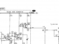
IG-5218 Schem
Test point A, also known as TP1 Is on the schematic. I attached the screen shot.
Reporting my voltages won’t help you as mine are off. I have found one resistor Which should be 2400 ohms and it is 1600, so when I get it and install I’ll check voltages again. But if you have the schematic, appropriate voltages are shown in the ovals next to each Q lead as shown in the screen shot.
I pretty much finished checking wiring and besides the wire missing to point AB I also found he had the IEC wired backwards; live to where Heathkit wanted the neutral and vice versa. Not sure how much havoc that might have wrought but we’ll see if things improve with the resistor.
Attachments
Hi Jeff,
Thanks for helping me find the test point--- I knew I was probably overlooking it.
Exchange of hot and neutral shouldn't cause any damage.
Sorry I was't very clear with what I was trying to recommend. I'm suggesting that actual voltages observed be used to help locate the fault.
You mentioned earlier some base voltages were near B+; Q1 and Q2? What is TP H voltage? Its value may lend insight. If pots R7 and R9 are working as intended, their wiper voltage and the base of Q2 should be in the vicinity of 21V irrespective of other faults. I suggest initial scrutiny there.
Steve
Ahh! I completely misunderstood your post. Thanks for your offer to help.
I had just about completed all the voltage tests to post here when I found another smoking gun. A bad solder joint on a leg of Q8 and a suspect one on Q6. Fixing those did two things; it significantly changed the voltages on Q1, 2 and 3 though a few are still well off the mark on the high side, and it got the unit functioning. The adjustment procedure can’t go as outlined as the feedback pot when turned full up as instructed pegs the meter and results in output voltage in the 15-16 v range and a skewed sine wave.
I will recheck voltages tomorrow and post them so you may perhaps suggest where to go next to get things better aligned closer to spec. The meter is adjusted accurately on the 10v output but is not even close on the lower settings. Frequencies are all within .1% or better.
Thanks again for your kind help.
Jeff
Jeff, it sounds like you're just about there!
I'm not sure why defects at Q8 and Q6 would interfere with operation of the sine wave section but I won't argue with your success.
I've attached a PDF I found somewhere online that has portions of the Heath manual.
You posted "The adjustment procedure can’t go as outlined as the feedback pot when turned full up as instructed pegs the meter and results in output voltage in the 15-16 v range and a skewed sine wave."
I think this may be normal behavior with the Feedback pot at full up. If you have a 'scope look at Figure 2 on Heath's page 43 and try to get the C waveform. Then trim the Feedback pot and the waveform should drop in amplitude and become a clean sine wave. If this is the behavior you observe, you've likely achieved success! The rest is solely calibration. Be aware that the meter shows an internal level and is affected by output level and range switch and internal/external load switch. It of course does not indicate amplitude at the output terminal binding posts.
Please let me know of continuing problems. Good luck!
Steve
Last edited:
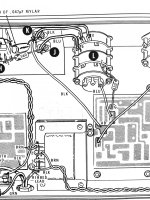
K lug and AB
The K lug is the lug connected to the backside of the black sine wave output post. Point AB on the PCB is not labeled. Attached is the graphic from the IG-5218 assembly manual. Hope this helps.
Jeff
The IG-5218 is the same as the IG-18. I can not find solder lug K or spot AB. Post a schematic with what you got. E
The K lug is the lug connected to the backside of the black sine wave output post. Point AB on the PCB is not labeled. Attached is the graphic from the IG-5218 assembly manual. Hope this helps.
Jeff
Attachments
I realize the current Heath Co is sensitive about their docs, but here is one:
https://www.vintage-radio.info/download.php?id=172
> The adjustment procedure can’t go as outlined as the feedback pot when turned full up as instructed pegs the meter and results in output voltage in the 15-16 v range and a skewed sine wave.
You "peg the meter" ONLY to set BIAS for equal clipping both ways. And this is not what I did. (I lived with an IG18 for decades.) Slamming the system is rude and approximate.
Bring up FB (feedback), at some point it suddenly sings real loud. Sneak it down, suddenly it stops. Now sneak it up then down very slow so it gets in the 7V to 11V range. Let it cook (and drift) a while. Sneak it back to some arbitrary point. Now sweep the Freq knobs and see if it stays roughly right at all freqs. Then diddle BIAS so it clips top then bottom. Note those points and set BIAS in the middle. (In a healthy -18 anywhere in the middle is about the same.) Let cook for a day. Now gently trim FB for a 10.0V output, confirmed by internal meter and trusted bench meter. (Many DVMs can't be trusted over 400Hz- trim at 100Hz and let the internal meter confirm the highs.)
Last edited:
Ok. Continued progress.
Following the manual adjustment procedure results in some glitches. Starting with the feedback pot at full CW, the waveform is severely distorted. Backing it off enough to get a sine wave with flat tops I am then able to even up the tops with bias adjustment. However the next step says to back off the feedback to get the meter to read 10. No can do. Minimum feedback setting still has meter pegged. I have to back off the fine amplitude control to get the meter to 10, which is supposed to be full CW at this point. When meter reads 10, my Fluke reads 10. The waveform at that point is pretty nice but not perfect, and it has an occasional jitter. On to the square wave setting and symmetry and all is well except for an occasional jitter there as well.
But to get rid of the jitters requires backing off the feedback even further. And at the point where the sine is nice and stable across the full frequency spectrum, nothing but spurious noise from the square wave side. Back to the manual adjustment process and both sine and square are Ok but occasionally jittery.
Not sure it is relevant at this point but both bias and feedback wiper voltages are ~21.5.
A cursory look at the FFT on my brand new Digital scope shows quite a bit of harmonic distortion but I have a learning curve to navigate on the scope so not too concerned about that yet.
If this is as good as it gets, it will suffice for most of what I’d like to do with it, but if there is room for improvement I’d be very appreciative to hear about it.
Thanks,
Jeff
You can't trust the '5218 meter reading until it's been calibrated by adjusting R21.
Make sure you're following the "ADJUSTMENTS WITH AC VOLTMETER ONLY" procedure on Heath's page 41. (This procedure is good for scope scrutiny as well.) By way of explanation, with the Level pot at max, the range switch on 10V, and the 600 ohm load switch set to external, the banana jack output is effectively connected at the junction of R107 and R108 with no external loading. You then tweak the Feedback pot to get 10V RMS at the output jack with the Fluke voltmeter. Finally, you trim R21 so the meter indicates 10V.
Erratic behavior is bit more of a challenge. PRR offered great advice above. Further, since the unit is so old, I'd recommend a thorough cleaning of all rotary switches and especially the pots with Deoxital contact cleaner or similar. "Exercise" the pot wipers a few times. This will probably help the erratic issues.
Once you have the generator behaving consistently, there are a number of hot-rodding threads about improving distortion performance. In particular, Dick Moore (RIP) did a lot of good work in this instrument. He was active in this forum.
You're making great progress! Cheers!
Steve
... mistake of making mods before checking basic functionality....
What "mods"?
The stock IG-18 is easy to trim. I applied an AA "upgrade" and it became a real dog, was never quite right, and I was too bull-headed to yank the mods and put it like it should be. If you have new mods on old mods and original-sin assembly, who knows?
If reasonable poking of dry solder joints and switch contacts does not quickly put you right, I would consider extended dismantling and careful study with bright light and magnifier, then gradual part replacement. If the won't-trim varies with frequency then it is a cap; if same at any F it is a resistor or transistor. None of the transistors are magic-spec. The power devices are unobtanium but any fast TO220 will do, without heatsink, after you tangle the leads.
Ok. You folks are generous with your time. Thank you in advance for a bit more.
The only mods I am aware of are the DataPro meter buffer board, C1 and 2 are 1000 mfd, and C3 is 470 mfd. Also a 56 nf cap has been added in parallel with the X1 5 mfd cap om the multiplier switch to bring it more in line with the multiples of the other positions. (If that is not clear say so and I’ll clarify). All the other minor upgrades I have seen recommended for IG-18s are already incorporated on this 5218.
To clarify, the jitters are better described as oscillating amplitude. For the most part, freq is rock steady per my scope and DMM with noted exceptions.
PRR could you be more specific about “sings”? The only thing that happens as I increase feedback pot is the amplitude goes up and eventually begins to distort the wave. As it approaches clipping the frequency begins to drop.
Following the voltmeter only setup, when the feedback is set for 6-8 volts and the fine amplitude is at 3 o’clock as instructed, the bias has no effect. At 3 o’clock fine amplitude setting the meter reads about 4 volts and min to max bias does not make it budge. The meter and my Fluke DMM match precisely.
I them adjust feedback for 10v at which point turning the tens freq switch also has no effect on the meter.
At this point scope shows a severely clipped slightly skewed waveform well below chosen frequency. Turning the fine amplitude back to max and reducing feedback back to 10 volts results in a much nicer unclipped sine, at the correct frequency of 1khz at this point but occasionally unstable. As I increase the frequency instability increases frequency error to the low side increases and eventually shows a sinusoidal waveform with filled-in peaks. Reducing bias stabilizes things. As I continue to raise frequency, less and less bias is required to return stability.
Barring any “aha” moments from you, I will try the overnight procedure PRR suggested.
By the way the multiplier caps are spot on per two different meters, as are all other PCB caps and the dipped cap on the outputs as well. Almost all PCB resistors have been checked also. All components have been checked for proper installation and good solder joints.
Thanks again,
Jeff
Following the voltmeter only setup, when the feedback is set for 6-8 volts and the fine amplitude is at 3 o’clock as instructed, the bias has no effect. At 3 o’clock fine amplitude setting the meter reads about 4 volts and min to max bias does not make it budge. The meter and my Fluke DMM match precisely.
I believe I see an error in the Heath manual!
Following the "ADJUSTMENTS WITH AC VOLTMETER ONLY" , note that on page 42 instructions call for the fine amplitude control to be returned to the full clockwise position followed by trimming of the Feedback pot to produce 10V. But in the "ADJUSTMENTS WITH AC VOLTMETER AND OSCILLOSCOPE" procedure, the instruction to return the Fine amplitude to full clockwise is missing! If you follow the first procedure, I believe you'll have a more favorable experience. There's no reason to not use your scope in concert with the voltmeter in the first procedure. Or merely return the Fine amplitude to full up prior to trimming Feedback amplitude to 10V RMS in the second procedure.
Amplitude "bouncing" when settings are changed is a normal phenomenon and amplitude should settle to equilibrium in a few seconds. Sustained amplitude fluctuations shouldn't occur.
Good luck!
Last edited:
Aha!
That qualifies as an “Aha” moment, Steve. That procedure now makes more sense and gets me to a fairly stable output.
But the bouncing continues perpetually, sporadically but a few times per minute. The bouncing is accompanied by a synced meter needle bounce. And at frequencies above about 50-70khz it increases until at some point it becomes continuous. As I near 100khz the waveform goes bonkers into an unsynced mess of no fixed frequency.
Now that I have the biggest overall improvement thanks to your and BSSTs help, I will go check all voltage test points again in an effort to identify a possible culprit.
Thanks again,
Jeff
Now the symptoms have me stumped but I'll offer some scatter-shot ideas.
With nominal calibration in place, seek out/provoke worst misbehavior. Sounds like this occurs at higher frequency settings. When misbehavior is active look at the 43V rail with your scope (ac coupled and high sensitivity). You're looking for possible oscillation on the supply. Also poke around with scope at Q10 for high frequency oscillation. This stage is an emitter follower with caps on all terminals; they can be oscillation prone.
Maybe your scope's FFT will provide insight about the spurious oscillation frequency.
Experiment with added 100nF ceramic bypass caps at 43V rail and in parallel with C5.
Try to look for "handles" (clues) that affect the misbehavior. We need insights!
Good luck!
Steve
Here’s some insight.
Haven’t scoped the rail but during wild bouncing there is no discernable change on 43v supply by DMM. I will scope that later.
But here’s an interesting smoking gun. The square wave is pulsed DC, all positive, no negative. Or, there is a positive 3-4 volt DC component, I can’t tell which. Still new to digital scopes and I’m still on the learning curve. Confirmed by DMM. I’ll send pictures of the scope to show that and how at low frequencies, the square pulses are not square either, they are fast rise spikes then rapidly declining to near 0 before the “negative” spike which really just goes to 0. Pictures will show this anomaly better than I can describe it.
Earlier I meant to suggest turning off the square wave circuit just to ensure it wasn't involved in the misbehavior or adding to uncertainty--- but I failed to offer that suggestion. I believe if you turn the Symmetry pot to the ground end that will disable square wave generation.
Square wave signal is strictly unipolar--- positive level switching to ground. To view square wave signals use dc coupling on your scope; ac coupling will add strange-looking (differentiating) transients.
Square wave signal is strictly unipolar--- positive level switching to ground. To view square wave signals use dc coupling on your scope; ac coupling will add strange-looking (differentiating) transients.
- Status
- This old topic is closed. If you want to reopen this topic, contact a moderator using the "Report Post" button.
- Home
- Design & Build
- Equipment & Tools
- IG-5218 Assembly error?