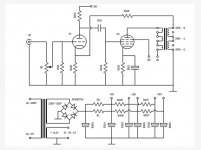
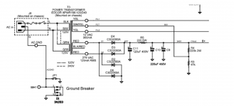
Schematic for a small SE EL84 amp

I have a 269JX Hammond PT, only has 60mA so I wanted to build a amp with one pre-amp tube in the 12AX7 family and one EL84 hooked up in Class A, SE.

Has anyone come accross a schematic like this that I can copy?

Also I am fairly new to the audio world using tubes and I have a few questions :
Because of the pre-amp tube does that make this amp intergrated?
Why is the volume pot located just after the RCA jack input and not after a pre-amp stage?
I have built tube guitar amps before and these audio amps look so darn close to each other what would you say the difference is?

Thanks!

another tseii question

Sorry for the non-stop questions but I am trying to get a better understanding of how everything works in these amps. Today I was poking around inside my amp and found that there is high voltage on the exterior cans of c6 and c7. Those are the caps in the bias supply. I measured and c6 shows -400v and c7 shows -200v. Is it normal? I double checked and the caps are installed with correct polarity.

Suggestions for subs for my Diatone DS-5000s

Hi everyone,

I was wondering, what would make a decent quality subwoofer(s) partner for my Diatone DS-5000 4 way speakers?

More info on my speakers see this link

DIATONE DS-5000

My main use would be music, with occasional (1x week) movie night. So focus is more music.

My room will be 6 meters length 3 meters high and 3.9 meters wide.

The room is rectangular with 30mm gyprock, insulation in the walls & ceiling & roof. A sold door and sound reduction windows. The floor is concrete covered with 20mm plywood and wool carpet.

I plan to have a sofa and a desk behind the sofa opposite the speakers which are going to be on the long wall.

I’m thinking DIY subs as I know a good cabinet maker. However I’m unsure what might be suitable.

The rational is to have a quality sub that can reach say 15hz Max.

Not sure about a suitable crossover frequency either with these speakers and subwoofers.

Thank you all for any advice in advance and I hope everyone is staying safe in these trying times.

Warm greetings from Australia

Tim

Troubleshooting Switching Power Supply (Fender Passport 250)

I recently acquired a non-working Fender Passport PA system. The prior owner believed that the issue might have been related to the transistors it uses (which is covered here in another thread) but my unit seems to check out fine.

The power amp/mixer utilizes a switching power supply (SMPS) which seems ot be the source of the problem. This youtube video shows the voltage (51VDC per side) which should feed the amp but mine doesn't show anything.
REPAIR FENDER PASSPORT 250 in Protect mode - YouTube

I'm not an EE and don't really know where to start troubleshooting the PSU for likely components that might fail. (Yes, I know there's high voltage involved and will short out the capacitors ).

The service manual is here:
FENDER PASSPORT PD-250 SERVICE MANUAL Pdf Download | ManualsLib

I don't believe there is another power supply out there that I can easy swap in so I'm left with working on this thing 🙁

If anyone has any recommendations on where to look or even what parts can be tested "in place" without having to first unsolder leads?

Thanks in advance.


Some pictures:

i2WNvXY.jpg


3TsTN0g.jpg


I don't think the unit uses blade style fuses but I'm not sure what these are for?...
5ZsFz54.jpg

Krell PCB SET - Pink mouse version

A set of new Krell Clone (Pink Mouse) boards as per pictures below. These are the heavier, thicker trace version and were expensive! They are unbroken and comprise

x4 output boards
x2 Driver boards, attached to:
x2 Main boardsTotal x8 boards

UK£40.00 Plus shipping

Also some Krell 100 boards…part built will be included! These are early American clones and include output boards + Output devices….PIC. will be added in 24 hours.

Thanks for looking.

Attachments

  • BDC_1247z.jpg
    BDC_1247z.jpg
    944.3 KB · Views: 248

Fusion FA123 - Protection Shutdown

Evening all,

I have just finished installing fusion fa123 amps to my 3 way speakers and dialled in basic crossovers. However, the left channel (slave amp) keeps going in to protection mode. The flashing light indicates a high temp. After I have switched them both off for a while and they have cooled down I find that the slave amp has reset the input setting to Auto and the volume to -96db. However, after switching the input back to SP/DIF and adjusting the volume the best I can achieve is a broken signal.

Any ideas?

Setting Phase Shift in Fusion HFD ?

Well! I'm absolutely made up that I have managed to get a basic 3 way crossover setup today using my new Fusion FA123 plate amp.

I have used second order filters across the board and I am told that there is a 180 degree phase shift that needs to be corrected. I am informed this can be done by simply switching the cables at the midrange driver but it may be possible to it within the fusion software??

Any done this in the HFD software?

Thought experiment..

If an acoustic instrument (A small one that's easy to get with single mic) was close mic recorded in an anechoic chamber in mono and played back on a single extremely accurate loudspeaker with high dynamic capabilities in the middle of a normal room (Where a typical musician would be standing) and with a window open, would someone walking by think it was a live instrument being played?

Hole Template Sample for CAD

Hello,
I would like to create a simple CAD drawing with holes on a rectangular template (16 1/2" x 12 1/2"). I'm a beginner with CAD, so any inexpensive or free software suggestions would be appreciated.

My project is a 300B amp, so I want to drill holes into an aluminum piece of sheet metal. I'd like to potentially send it to a small machine shop for fabrication, so STP/STEP format for the shop would be required.

If anyone has a sample file with some holes already defined, I can reverse and modify from there -- just need to get started.

I have all my holes measured and would like to feed them via an Excel worksheet to be plotted.

Thank you!

6P13S SE cheap amp: improvement suggestions

Hi,

I had a coupon on ebay last month, plus a coupon from a local toroidal supplier, so I bought this cheap amp kit with chinese tubes 6P13P that are equivalent to russians 6P13S:
TUBO a Vuoto HiFi 6P13P Amplificatore classe A Single-Ended POWER AMP BOARD Kit fai da te | eBay

s-l400.jpg


The schematic is attached.

I would like to improve it with the following:
  1. removing gnfb (have a bit more gain to apply other feedback methods)
  2. connecting R103 to the first 3rd of the OTP primary (shunt feedback)
  3. connect a 90/100V zener diode from cathode to screen (fixed screen-cathode voltage)
  4. add a screen resistor (safety)
  5. connect R105 and E101 to the 8 Ohm speaker tap. (cathode feedback)

I would like to make them work at 270V B+ 50mA at idle and 5 kOhm primary impedance (see attached working point) to have around 5 Wrms.
Well, in theory, as I doubt the OPTs can supply that much power in the whole audio range...

Would you suggest to add an additional winding on the power trafo to have fixed bias?

Is there anything else you would suggest or do differently?

Thank you in advance,
Roberto

Attachments

  • GFB734B.jpg
    GFB734B.jpg
    46.4 KB · Views: 1,215
  • EL86 - 6P13S SE.png
    EL86 - 6P13S SE.png
    38.1 KB · Views: 975

Classe Cam 200 released the genie

Classe CAM200, owned since new. The amps were stored for about three years. I hooked both up recently and when they were powered on I got pretty dramatic sparks and smoke. Working perfect with no issues prior. Packed original boxes and stored in climate controlled, dry closet. Power cord to Furmann, XLR to preamp. The power chord and XLR tested and are not defective.

Any ideas what went wrong? Looks like the resistors exploded! I'm hoping I can just replace the resistors and give it a try.

Shared album - Rob - Google Photos

fixed link

Philips CDM1 tracking problem

Philips CD960 PLAY function problem

Hello,

I'm restoring a Philips CD960 and I've run into a problem with the PLAY function.

I'll try and explain..

If I load a disc the player quickly reads the TOC but if I select PLAY it just continues to spin the disc and it won't play the track selected.

BUT if I start the player in service mode 3 it plays perfectly (sounds great too) and I can move between tracks using the search buttons (as described in the service manual). Once going in service mode 3 it'll continue to play just fine. So, the laser is focus is obviously fine and the radial motor is able to move the arm.

I don't know the correct terminology but the player is failing to 'lock' onto the track selected somehow. I think maybe there's an issue with one of the requisite signals between the various IC's?

Laser power is correctly set at around 600mV and the focus offset is OK.

I have replaced the five electrolytic capacitors on the board under CDM1 mech.

The swingarm moves freely.

Any ideas? I'm stuck.

I have a CRO and a copy of the service manual.

Trying to understand the Naim Armagedon power supply, please help

Ok so I want to understand the Naim power supply. It uses an isolation transformer to isolate the motor from any noise in the line from the wall, correct. Then it uses a resistor to step down the voltage, and a .2uf capacitor for phase shift.

Other than the transformer, the typical power supply used in many AC Sync turntables right? Could a similar method be implimented on any AC Sync turntable simply by using a filtered power supply with isolation transformer. Would a possible way to upgrade the power supply be to replace the transformer with one that offers isolation and also reduces the voltage down to the needed one, say 12 volts, and have it be of a larger VA rating. Do they make transformers that both isolate and reduce voltage, would that be essentially a step down transformer?

Ok final question, do you think the quality of the phase shift capacitor would really make any difference, I know Naim used a different one, but is there really any difference between say the quality of the cap used in the naim and that used in the Linn Basik. I don't have a Linn, I have an Acoustic Solid now which uses a 12 volt AC Sync motor. They offer a very expensive microprocessor controller, and I was curious about implimenting a Naim style system with the A-S since it would probably not cost all that much.

Mc2105 one channel has loud beating sound

I have a McIntosh 2105 I bought new in 1967. After all these years yesterday when I turned it on all was fine until I turned up the gain. Then the left channel put out a super loud beating noise. The right channel is OK. I am not sure whether there is any audio from the left channel any more or not. Any ideas about what could be wrong? I am definitely not an electronics whiz. I can solder but I don't really know much more than that. Many years ago I built one of those HK Citation pream kits and it worked fine, but that was just a "paint by numbers" kind of job. My only test equipment would be a volt/ohm meter, a new one but more for car work than stereo.
Any ideas?
Thanks in advance.

Salas SSHV2 + Moglia hybrid mu-follower

I'm very disappointed, (looking for the best SQ I used both devices togheter because both separately the SQ is top notch) the SQ togheter is very bad: cutt off highs & the left the sound only one dimension & lifeless.

I post here to know if other people is in the same situation as me, also asking if there is a technical reason for the bad sound.

Understanding SOA

There is an aspect of rating transistors SOA I do not understand for class AB amplifiers.


On the SOA graph,


Ic = Output Voltage / Load Impedance
Vce = Rail Voltage - Output Voltage


(for Load Impedance approximately real and constant). Plotting Ic vs. Vce is called the "load line" I believe. When Vce is small, Ic is high (near the rails), and when Vce is large (near zero output) Ic is low.


For a transistor with a constant collector current, this load line is plotted on the SOA graph. It should remain under the SOA graph, properly derated for temperature at constant power dissipation.


For sinusoidal rather than constant Vce, high Vce only occurs near zero output. Therefore for a purely resistive load, the part of the SOA near second breakdown occurs only for the brief period near the zero crossing. So one would expect that the useful SOA would be somewhat better than the DC prediction.


However, with reactive loads, it is possible to have high current near the zero crossing because of the lead/lag of Ic relative to Vce. How does one account for this? Is using the DC prediction for SOA typically considered safe for this, or is there some other criterion?

Yet another floor to ceiling line array (25x Aurasound NS3)

Hi,
here I'm documenting my my current line array build. I'm mostly done with the wood working and have set up a basic DSP. A Raspberry Pi Zero running Funtoo Linux (a Gentoo derivative) + BruteFIR. Why not Raspbian? In my experience Gentoo based distros run faster than Debian ones (obviously useful on slow devices) since your system is tailored exactly to the hardware. But that discussion is fuel for endless flame wars, so I stop here. 😀

Back to the topic. The Pi is connected to a CM6206 based USB interface (8 analog 16 bit / 48 kHz outputs, two inputs. Plus Toslink in and out). Filter coefficients are created via DRC Designer on my measurement laptop running Windows 10 (I'm planning to do the filter creation directly via DRC-FIR on the RPi to simplify things and get rid of Windows).

Just a few hours ago I've finished the BruteFIR configuration. I'm getting music out and the CPU load is on a moderate level (~63%), no clicks and pops but it sounds awful, like a 64 kBit MP3 or worse, no highs. I'm getting better sound by only using the built-in 10 band EQ from my media player. I'm awaiting another USB sound card to be delivered in a few days so I can measure what's being wrong exactly.

I think I'm going to correct the low frequency roll off via a Linkwitz transform circuit straight down to 20 Hz (Yes, that's a ton of gain, fc is around 140 Hz. Small sealed enclosures need a lot of power, total enclosure volume per driver is 0.75 l...) and do the 3 dB/oct high frequency fall off compensation via analog circuity too and leave the fine adjustments to DRC-FIR.

Here's my current BruteFIR config, if someone is interested, two channels, one way. I had to convert the stereo .wav from DRC Designer to two mono raw files via the tool sox to be accepted by BruteFIR.

Code:
## GENERAL SETTINGS ##
filter_length: 65536;

## COEFFS ##

coeff "left" {
	filename: "left.raw";
	format: "S16_LE";     # file format
};

coeff "right" {
        filename: "right.raw";
        format: "S16_LE";     # file format
};

## INPUT ##

input "left", "right" {
	device: "alsa" { device: "hw:0";};  # module and parameters to get audio
	sample: "S16_LE";   # sample format
	channels: 2/0,1;    # number of open channels / which to use
	delay: 0,0;         # delay in samples for each channel
	maxdelay: -1;       # max delay for variable delays
	subdelay: 0,0;      # subsample delay in 1/100th sample for each channel
	mute: false,false;  # mute active on startup for each channel
};

## OUTPUT ##

output "left", "right" {
	device: "alsa" { device: "hw:0";};  # module and parameters to put audio
	sample: "S16_LE";   # sample format
	channels: 2/0,1;    # number of open channels / which to use
	delay: 0,0;         # delay in samples for each channel
	maxdelay: -1;       # max delay for variable delays
	subdelay: 0,0;      # subsample delay in 1/100th sample for each channel
	mute: false,false;  # mute active on startup for each channel
	dither: false;      # apply dither
};

## FILTERS ##

filter "left" {
	from_inputs: "left"/0.5;
	to_outputs: "left"/0;
	coeff: "left";
};

filter "right" {
        from_inputs: "right"/0.5;
        to_outputs: "right"/0;
        coeff: "right";
};

I've started the build on Oct 26. Here are some pictures:

1 - First baffle chamfered on the back side
2 - Preparing the second baffle
3 - Both baffles done
4 - Cut outs on the first baffle done
5 - Driver fits 😀
6 - Cutting out the second baffle
7 - Both baffles done
8 - Preparing internal cabling. Five drivers in series, five groups parallel for 8 ohms impedance or all in series (200 ohms) for OTL experiments (I have lots of 6P45S sweep tubes to be used and enough power transformers for circlotron amps)
9 - Hooked up some cheap chinese 30W Class D chip amps for testing purposes
10 - Drilling 200 holes... 😕

More pictures in the following posts.

Attachments

  • 1.jpg
    1.jpg
    136.5 KB · Views: 186
  • 2.jpg
    2.jpg
    170.4 KB · Views: 179
  • 3.jpg
    3.jpg
    134.8 KB · Views: 173
  • 4.jpg
    4.jpg
    131.4 KB · Views: 176
  • 5.jpg
    5.jpg
    101.3 KB · Views: 190
  • 6.jpg
    6.jpg
    145.3 KB · Views: 111
  • 7.jpg
    7.jpg
    131.7 KB · Views: 108
  • 8.jpg
    8.jpg
    157 KB · Views: 113
  • 9.jpg
    9.jpg
    86.2 KB · Views: 92
  • 10.jpg
    10.jpg
    100.5 KB · Views: 117

FS: Two Fisher Elektronik SK56 heatsinks

I have for sale two (2) Fischer Elektronik SK56 heatsinks. Both heatsinks already have some M3 threads, made for Holton NXV200 amplifier board and power supply unit (mine design). Dimensions are 300x80x40 mm. Weight is cca 1,3 kg/piece.

Price is 15 EUR/piece + post costs. Payment via PP.

Attachments

  • sk561.jpg
    sk561.jpg
    129.3 KB · Views: 599
  • sk562.jpg
    sk562.jpg
    144.3 KB · Views: 596
  • sk56.jpg
    sk56.jpg
    41.8 KB · Views: 597

Hybrid SE 8W - Aikido + Mosfet

Hi,

I am making project for fun. My friends asks me quite often, that they would like to have tube + solid state hybrid amplifier. Inspired by moskido amplifier, I designed one.
For the tube front end I am using half of aikido amplifier (to reduce number of tubes). Power amp is single ended class A.
Poweramp should make about 8W to 8 ohms and 16W to 4 ohms.

What dou you think? Is it worth building?

Attachments

  • SE HYBRID CLASS A 5W.JPG
    SE HYBRID CLASS A 5W.JPG
    252 KB · Views: 227
  • Like
Reactions: ziffel

WTB: F5T jfets (EU only)

Hello lads,

I need either 2SK170 or LSK170 and the complementary LSJ74 or Toshiba equivalent - total of 8 pieces each.

We ordered most parts from the diyaudio store but have not seen these are not included in the transistor kit. US postal service was mediocre on both orders froom the store, one took 3 months to arrive and was somewhat lost for a month or so, hence my very strong preference to source them from the EU.

PM me if you have them.

Thanks,
Mario

Arylic Up2Stream with Allo Piano 2.1 issues

Hey there,

(I'm from France, sorry if I make English mistakes 🙂 )

I'm trying to do this DIY project but I'm not very familiar with some of the part's i'm using. I did not find anyone that has tried this specific setup before.
Here is the idea :

I want to use the Arylic Up2Stream Pro v3 as my main source for powered speakers to make them wireless. I'm going to make a pair of them, with an active crossover. (I want to use 1*up2stream and 1*Piano in each speaker, as the two Up2Streams can become a stereo pair)

1: Is it actually possible to use the Up2stream and Piano together ? (without a raspberry Pi)

2: If it is possible how exactly can I wire them together ?

3: About the DSP in the Piano 2.1, I'm planning on using it for the active crossover, by getting a mono signal from both Up2Streams and then splitting the signals into meds and highs, before sending them to the drivers. I hope the Piano's DSP can be programmed to do this. If so, I assume this is done through a raspberry Pi, as I don't think there is another way of connecting it to a computer.

Then, would the Piano 2.1 run with an I2s input from the Up2stream with the DSP program after being disconnected from the RPi ?

I would really like to know if all of this can work or if i'm forgetting something.

Thanks for your help ! 😀

WiFi&Bluetooth 5.0 Multi-room Stereo Receiver Board-Arylic.com
– arylic

Piano 2.1 DAC

Tape to hold wires against PCB

I'm working on a Sony Walkman that came from the factory with various sections of wire held to the PCB with tape. Some of this mystery tape has lost its "stick" after all of these years and needs to be replaced. It has almost like a fabric outer side. Does anyone know what would have been used here or have suggestions for a substitute?


(Not my picture, but it's the same model.)

Attachments

  • PCB Ref 1.jpg
    PCB Ref 1.jpg
    239.2 KB · Views: 489

Connecting a Headphones DAC to Speakers

Connecting a Music player that contains a Headphones DAC to Speakers

Hi all


The companyh HiBy makes 2 nice Music Players:


HiBy R2:

HiByR2.jpg


HiBy R2 MP3 Network Streaming Music Player HiRes Lossless Digital Audio Tidal MQA 5Gwifi LDAC DSD web radio Bluetooth 5.0|HiFi Players| - AliExpress


HiBy R3Pro:

Hi-By-R3-Pro.jpg


HiBy R3Pro MP3 Network Streaming Music Player HiRes Lossless Digital Audio Tidal MQA 5Gwifi LDAC DSD web radio dual CS43131|HiFi Players| - AliExpress


The HiBy R2 is based on ES9218,
and the HiBy R3Pro is based on 2x CS43131.


These 2 DAC chips are DACs that include a built-in Headphone Amplifier.


In my case, I do not use Headphones, only Speakers.
I have 2 Yamaha HS7 monitors (amplified), that I wish to connect one of these players to.


My question:
Does the fact that these 2 music players contain a Headphones DAC and not a regular DAC, affect/degrade the sound in any way,
when connecting one of these players to amplified speakers instead of to headphones?


Thank you

FS/FT Behringer A500 amp

Behringer A500 stereo power amp. Nice unit, Great condition. 100% operational condition with no issues. Small black mark on faceplate in picture is a camera fault, not on unit.

From Behringers data sheet

A precise level meter and clip indicators are provided for accurate performance monitoring. Input connections are laid out on balanced XLR, 1/4" TRS and RCA connectors, making sure you never run out of connectivity options

• For recording studios, post-production, live sound, and hi fi applications
• Servo-controlled design can drive virtually any passive speaker
• Advanced convection-cooling for absolutely noise-free and stable operation (no fan)
• Precise level meter and clip indicators for accurate performance monitoring
• Quality components and exceptionally rugged construction ensure long life
• Speaker outputs on professional "touch-proof" binding posts and 1/4" TS connectors
• Ultra-reliable Toshiba® / Fairchild® high-power transistors

Specifications: • Output power (RMS, 1 kHz @ 1% THD): Stereo mode (both channels driven): 125 watts RMS x 2 @ 8 ohms, 185 watts RMS x 2 @ 4 ohms; Bridged mono: 375 watts RMS x 1 @ 8 ohms • Output power (peak power, 1 kHz): Stereo mode (both channels driven): 175 watts x 2 @ 8 ohms, 300 watts x 2 @ 4 ohms; Bridged mono: 600 watts x 1 @ 8 ohms • Weight: 18.5 lbs. • Dimensions: 4" H x 19" W x 10.85" D.

Check out my eBay feedback rating jkeaft2, 100%

Would consider trade for pair of 30 watt tube output transformers.

Payment via PayPal. Buyer pays shipping (and insurance if wanted). Asking $130.00, obo, or trade.

Attachments

  • Dscf2865resize.jpg
    Dscf2865resize.jpg
    48.1 KB · Views: 110
  • Dscf2868resize.jpg
    Dscf2868resize.jpg
    52.4 KB · Views: 114

Question about SS output stage?

Is it possible to add more output transistors to an output stage in parallel to increase the current capability of the amplifier?

An example would be the JLH design revised by the Sound-AU guy. (schematic attached) There he used an MJ15003 as the outputs (refering to schematic 3, high power version) what if I just added another pair keeping all values that same? I'm not modifying his design I'm just using his design as an example, it just happens to be what I last read about.

Specific question

1. Is there changes needed for the bias design to keep the outputs biased to the original design specifications?

2. Is there a need to increase the heat sink design for any reason other than using lower impedance loads resulting in increased current demand.

3. Is there changes needed to the emitter resistance and wattage used?

4. Does the driver stage need to be modified to handle increased current from the output stage. If so can a driver stage transistor of transistors be paralleled as well?

5. Is there any other changes needed that is not considered by the questions asked above?

Attachments

  • jlhupdatefig1.gif
    jlhupdatefig1.gif
    7.9 KB · Views: 195
  • jlhupdatefig3.gif
    jlhupdatefig3.gif
    9.5 KB · Views: 201

What in the world are these speakers? Cardboard tube speakers

Sorry I don't have any better pics. These are advertised for quite cheap on Craigslist. Anyone have any idea what they are? No additional details on the ad other than rough dimensions. The big ones are apx 15", medium are apx 12", small are 8" and look like they have a whizzer cone.

The advert says theyre from a "hammond organ" but that cant be right

Attachments

  • 126899865_10221136367497735_1763376082819635640_o.jpg
    126899865_10221136367497735_1763376082819635640_o.jpg
    26.1 KB · Views: 219
  • 126860405_10221136367697740_7080944810732081819_o.jpg
    126860405_10221136367697740_7080944810732081819_o.jpg
    60.9 KB · Views: 233

150 Hz / 250 Hz / 350 Hz noise in linear PSU

I recently modified my PSU used for a Class A power amp (-+23VDC and 1.5A bias). I made these modifications:

- removal of softstart NTC at primary side of transformer (it was running too cold)
- change from Schottky diodes to standard 35A bridges (to get stable and less voltage drop over diodes)
- use a mains sinus re-generator to get perfect sine and very low mains impedance (< 8 mohm) and also to get a stabilized AC (230 VAC).

The changes has caused that my DC rails are very stable and my DC offset of amp is stable at 2 mV and it stays there over time.

The PSU has CRCLC filtering and when I use a DMM set to AC the rails just shows 0.0 mV so I have very little noise. However I noticed using REW software that I got some 150 Hz / 250 Hz / 350 Hz / 450 Hz peaks which was not visible before modifications. My 50 Hz and 100 Hz peaks are below 110 dB when I output about 3W at 1000 Hz into 6.8R load resistor. The 150 Hz / 250 Hz / 350 Hz peaks are just below 100 dB. So nothing to worry very much about. I am just interesting in knowing how these peaks are generated as I assume they must be 50 Hz harmonics? ....but my 50 Hz noise peak is very low so how can 150 Hz / 250 Hz be higher?

I guess if I introduced a small resistor just after the diode bridge it would limit the charge current very much and then also maybe remove the noise peaks. Increase of the R in CRC could probably also make a difference. But first I would like to know if others has seen something similar and know how they are generated?

Thor speaker – lots of help needed please!

Hello all,

I am looking for advise on a version of Thors that I have built. I will start by saying that I am a Civil Engineer and know absolutely nothing whatsoever about electrical engineering or speaker building. I appreciate there are hundreds of threads on this website on the subject but to be honest, it is difficult to find definite information and as time has gone on, advice seems to have changed.

Firstly, the reason for the project. I have a Cyrus system including a Streamline 2, DAC XP+ and two Stereo 200 amplifiers. I had Dali Ikon 6 speakers for years which I always enjoyed as they were detailed and entertaining, but were too bright for my room, which is unsuitable for a hifi, being a large conservatory with hard glazed and wooden walls/ ceiling with a high apex and a stone floor to top it all off! I bought some PMC 20/24’s and although it solved the bass problem, they just weren’t powerful enough to fill the room and I always felt that the midrange was too quiet when compared to the Dali’s. Therefore, as you do, I came to the very obvious and sensible conclusion to build my own speakers…

So to cut a long story short, I’ve been in the process of building my own version of Thors over the last 10 months and due to the time that it has taken, I have taken bits of information from this forum, knitting it together and ended up with the speakers that I have. Now I look back at the notes I made, mostly on scrap bits of paper, it’s not always immediately apparent why I made certain decisions and finding my way back to the original posts has proved impossible, partially as my research was often undertaken whilst travelling on trains on the way to work etc etc.

Anyway, in summary, I have built the following:

• Thor cabinets to the dimensions shown on the attached ‘Cabinet dims’ pdf although I’m still to fix the angled bits at the bottom. As you can see from the photo, I've created a separate compartment at the top of the speaker which contains the crossover for ease of access!
• Seas W18EX001 midrange drivers (note the ‘X’ i.e. not the W18E001 and I’ve attached the datasheets for both versions)
• Seas Millennium T25CF002 tweeters
For the crossover, I looked at various versions of jimangie1973’s as follows:
• I have built the crossover shown on the attached ‘Thor XO’ pdf (I think this was taken from the thread ‘Clarity on Seas Thor kit’, post 998
• I note that there were earlier version(s), which I assumed were superseded by the above
• I have subsequently found an even later version from 2015ish, thread title ‘Curved Small Thor Redux’ post 1 (attached 'Thor XO circa 2015' pdf)

They have been up and running now for about 3 days and I am fairly pleased with the sound, they are definitely improving with use and I’m not doing a comparison against the PMC’s until they have run in properly. However, it feels that I’m not getting the full spectrum of music if I can put it that way, there are parts of the music that are too quiet. And there isn’t the soundstage that I was really hoping for.

Also, having initially stuffed them with the metric equivalent of 0.75lb/ft3 of sheeps wool following advice from the forum, the bass completely disappeared, which seems similar to other people’s experience. I played around with this and currently have only 150g (0.33lbs) of insulation in the first half length and nothing in the last half, the result being plenty of bass, particularly as both speakers are close to a solid wall, one of which being tight into a corner.

My queries are as follows:

1. Which is the correct version of the crossover, or perhaps a better question;
2. Do the crossovers needs adjusting to the incorrect midrange drivers that I purchased
3. Does the reduced quantity of stuffing cause problems with the transmission line effective length and am I best not touching this until I have everything else sorted out
4. I’m sure that the only way to analyse this is to take measurements but

I have no idea what equipment (hardware and software) that I need to purchase. Obviously I don’t want to spend a fortune
I would be very grateful for some advice.

Thanks
Alex

Attachments

DIY DAC made with dam1021 making noise when rpi4 is turned on

I have made a DAC with Soekris dam 1021 which is also connected with rpi4 via i2s interface. I am using a digital switch to switch between rpi and amanero combo384. All the connecting cables with rpi4, switch, amanero combo384 and dam 1021 are shielded signal cables. The rpi4 is powered by ups and ups is powered by smps 3 amp mobile charger. Previously I used rpi 3b + and that time there was no noise even at the full volume. But recently I changed to rpi4 and I am getting noise even at low volume. The noise goes off when rpi4 is powered off. My amp and preamp is parasound halo 21 and p6 and it is perfectly alright as it playes other sources quietly. Need yor kind help and suggestion.

Attachments

  • 20201118_222322.jpg
    20201118_222322.jpg
    1 MB · Views: 132
  • 20201118_222327.jpg
    20201118_222327.jpg
    1 MB · Views: 127
  • 20201118_222342.jpg
    20201118_222342.jpg
    1 MB · Views: 118

Valves FS.

Mullard EF36 NOS tested - £8
Two RCA 1625's NOS tested - £20
Two Pinnacle 6N7's NOS tested £12


Postage to UK, £3.10,can ship overseas. Note there will be a slight delay in posting as we are on lockdown in the UK.


TFL, PM if interested, Andy.

Attachments

  • DSC03104.JPG
    DSC03104.JPG
    162.7 KB · Views: 143
  • DSC03105.JPG
    DSC03105.JPG
    161.4 KB · Views: 147
  • DSC03106.JPG
    DSC03106.JPG
    159.4 KB · Views: 141
  • DSC03107.JPG
    DSC03107.JPG
    162.9 KB · Views: 129

Hypex NCore NC500 build

Hi All
First post here. Thanks for all the info you guys share and some amazing projects going on out there.
So I've been putting together some Hypex Amps to sell a UcD180 UcD400 and a NC500 based amp. The NC500 certainly has some grunt! here are a few pics so far. I'm now on the search for a preamp to complete the line up. I have some cases coming in to evaluate. The idea is to mill the front panel and perhaps add some veneer as I also build IPL Acoustics kits and do lots of veneering. If anybody out there needs a few pointers in veneering or building IPL kits I would be happy to offer advise.
006_zps9ggbt0sf.jpg

IMG_1717%20-%20Copy_zpswvt2e35l.jpg

ed3e816f-eae5-4e63-ae98-0858c1d4ee86_zpsi2diumxk.jpg

Voltage multiplier

What on earth am I doing wrong? I am having problems with this phantom power circuit. Voltage regulator is working. I can turn right down to next to nothing. I copied this schematic and assembled it to the best of my ability. The voltage multiplier is not working on either of the 3 outputs. I am getting approximately 18, 18 and 36 where I should be seeing maximum of 36, 36 and 48Volts.
Any help would be greatly appreciated.

help needed for a basic setting

hi!
i'm a newbie and i'm having some trouble with my design...
there's too much buzz, absolutely not tolerable.
in the thumbnail is my setting

the raspberry and the mux share the same power supply.

if i feed the mux with a separate power supply (battery or phone charger) everything is ok, there's no noise anymore but it is alway on!!! (this was expected)

i tried with a second "bridge rectifier+ldo" on top of the mux, sharing the secondary output from the toroidal meant to work for the raspberry, but it's the same buzz
i think only a relay can save me
do you want to help me?
thank you

Attachments

  • my schematic.jpg
    my schematic.jpg
    154 KB · Views: 119

Phone Music Server, USB DAC, Web Interface ?????

I'm looking to setup:
- Unused Android phone as a music server (phone music storage, playback control)
- Output: phone USB to DAC to my audio system (not output using phones DAC via headphone jack)
- Preferably with volume control (connected to old equipment so remote volume control would be nice)
- Local interface/control via phone interface
- Remote interface/control via web interface (tablet WiFi to networked phone audio server)

I've searched the web but I'm not finding solutions that address the above. There are solutions for various parts of the above but not a comprehensive solution. I doubt I'm the first to want such a solution. That said, I may not be seeing it if right in front of me.

I've seen that you can do all the above with a R-PI but I have some old phones that are much more capable and unused.

Thoughts? Solutions?

Thanks in advance

EL34 Push Pull Amp Design

Hello all! There was some previous discussion of this topic in a previous thread, but it was pretty off topic from the original title and question, and I figured it was time to start a new one. In the last thread, the conclusion I came to was that EL34s would be a good and fairly cheap tube to design something around.


I would like to build a monoblock, as I both don't have the budget for an integrated stereo amplifier, and it also has other power supply complications that I would prefer to not deal with, as I can always build a second monoblock.


In terms of what I would like for output power, something around 40-50 watts would be nice, as that should be plenty for driving my not-very-sensitive Koss bookshelf speakers, but I may also use it to drive a Bose speaker, which is currently plenty loud with a 50 watt solid state amp. I generally listen to a lot of rock music, and often want it quite loud, and I know that 50 watts is plenty. In the previous thread, I got recommended Dynaco A470s from Triode Electronics, and with it's 4300 ohm load, with a B+ of 400 volts, it's load line looks quite nice, provided the screen tap percentage is the 33 percent I read it is. I think UL is probably the way to go, as it means I don't have to deal with regulation for full pentode mode, but also don't sacrifice much power like I would with triode mode. However, the Dynacos are a bit expensive, as I don't have a huge budget. I'll probably build the chassis myself with help from my dad, but I'm a high school student, and so my income and budget are quite limited. Would there be any disadvantage to going with something like Edcor iron? (aside from the long lead time)


I also looked at some 6600 ohm load lines, and with a B+ of 450 volts, they also looked quite nice.


Mostly unrelated to my questions, but I was talking to my Dad, and he was saying how lucky I am to have this forum as a resource, compared to when he and his father would have been learning electronics. It really is like standing on the shoulders of giants.


Thanks, and let me know if I need to clarify anything!

JVC / Nivico 5003 Repair

Hello--

I recently acquired a JVC 5003 from my parents place. It was missing the glass fuse holder cap, so after replacing the holder, I got to fire it up. Luckily no smoke came out, but the only thing it does is produce a moderately loud 60hz hum from all the speaker outputs. None of the other functions do anything, nor does flipping any of the tone controls.

There is a schematic on hifiengine.com (I can post here if need be) however it is missing the power supply portion.

I would be very grateful if someone could walk me through testing the various parts of the board and determining what the issue is!

Attached is the audio recording of the hum, and two pics of the power supply area.

Attachments

  • 20201119_020920.jpg
    20201119_020920.jpg
    128.2 KB · Views: 137
  • 20201119_020939.jpg
    20201119_020939.jpg
    118.4 KB · Views: 119
  • JVC 5003 noise.zip
    JVC 5003 noise.zip
    99.3 KB · Views: 50

PCM1702 PCM1704 PCM63 (PCM 63 1702 1704) sensitive to >>5V on one of the supply rails

PCM1702 PCM1704 PCM63 (PCM 63 1702 1704) sensitive to >>5V on one of the supply rails

PCM1702 PCM1704 PCM63 (PCM 63 1702 1704) sensitive to undervoltage on one of the supply rails ?

I have heard from some guys, that it is very important, that both pos. and neg. voltage values while start up phase must increase with absolutely identical speed, because with different values in the pos. and neg. rail can trigger a defect or a non-resettable internal error.

The same also applies after switching off, so that even the zero value comes about at the same time.

Is that really true ??

If yes, an appropriate switch-on delay unit in the 5V rails is necessary - this would have to be provided in any case to ensure that exactly 5V is present at exact the same time on the positive rail and the negative rail (maybe with help of solid state relay).

OTOH - such an unit I haven't discover until now in any D/A converter device on the marked equipped with one of the in the headline mentioned IC's.

Thank you very much for an information.

Identifying exploded C32 / C33 in Quad 22

I'm putting together a BOM for my Quad ii / 22 restoration and I'm trying to figure out what C32/33 is and what to replace it with. Is it an old version of a class x or y mains suppression cap? It's shown as a pair of 0.05uF 1000v caps each in series with a 220 ohm resistor, and in my unit they're joined together as a pair with the resistors all in one component, which has exploded and spread its guts around inside the preamp.

They're on the right hand side of the schematic attached

Attachments

  • Screenshot 2020-11-17 at 20.31.45.png
    Screenshot 2020-11-17 at 20.31.45.png
    614.6 KB · Views: 216
  • Screenshot 2020-11-17 at 20.34.34.png
    Screenshot 2020-11-17 at 20.34.34.png
    508.5 KB · Views: 216

Tremolo with 12AU7

Hi,

I wanted to build a tube tremolo for a small amp, but the only double triode that I had available was the 12AU7, mainly because of the low gain.

Well, the 12AU7 has a much lower gain than the 12AX7, which requires some extra stages until the LFO starts. I used LTspice to make some simulations and tested it with the small amp I'm building and it sounds good.

According to Merlin a three stage CR network requires a gain of 29, so I just added another one, but it was quite unstable and the oscillation was only starting at the settings right in the middle of the potentiometer. So, I decided to add another stage and make things better. I also had to increase the resistors and caps, mainly because of the parts I'm using.

Because I couldn't find an affordable switched potentiometer I decided to use the end of the pot to turn the effect off. This way at one end the tremolo stops, and the other end gives the lowest oscillation.

In case you're interested here is my final schematic:
jnhasdzl.png

EAR 834 clone & Denon DL 110

I'm planning on making an EAR 834 clone and I have a nearly new (not really run in) Denon DL 110 in my Rega Planar 2. I'm currently struggling to find a preamp that works well with the 110. Its output is too high for MC stages and too low for MM ones - it works with them but I'm lacking volume.

Will I be able to configure the 834 to produce enough gain to drive my power amp properly with the 110? My amp is a Claus Byrith 4-30, which can take up to 600mV, and the 110 produces a claimed 1.6mV.

Selection of FET configuration for a 10w Amp

Hello people, how are you?

I (a newbie) need help with a project I'm trying to design for personal use and as a university assignment project. The idea is a to keep it simple using discrete components (can't use Op-Amps or TDAs) and not to do a 50 transistor amp.

I want to design a 10-ish watt amp circuit that is a mix of a Tillman kind of preamp (I did this already but using a BC547 in CE with RE config) with a 10w power amp, but I cant decide which configuration or component to use.

My first idea was to use a single IRF510 and power it with a 50v supply , but then I read that is preferably to use a 2SKXXX family device in a complementary configuration.
I know that i want to select a component that will deliver 10-ish watt or a bit more at 50~60% of the max Pd rating. But after that i can't decide how to select the best config. I want the power stage to be the most clear and transparent possible

So i should go with a IRF (or IRL), 2sKXXX o even a tip201?
Is better to use a class a single mosfet amp design to preserve the signal as original as posible or to use a double device complementary design?

Thanks in advance, and sorry for the newbie way of asking this

Lacking of bass "punch" in my esl's

Hi,

I have a few topics at this forum about my DIY electrostatic panels. This one is about my latest creation:

My new stats, model #4

Yesterday a friend took some cd's that contain a lot of bass ('punchiness' / pressure at low frequencies). The music sounded rather flat on my stats. After the test we tested my 2-way Scanspeak DIY transmission line boxed loudspeakers and it sounded way different: it had a lot of 'puch': pressure. This particular music was made to be punchy / use a lot of pressure at lower frequencies.

My stats sound very fine in my opinion for the music of my personal taste (classical music, some pop music, electronic music, human voices). But this type of music lacks bass 'energy':

Mute Records • Diamond Version • EP4 - Out 6 May on 12" & Download - Mute Records

This isn't a big deal as normally I don't listen to this type of music, but from a technical point of view I'm interested in what exactly causes this difference between the esl and boxed speaker, and would commercial esl's show a similar difference?

When measuring frequency responses at listening position I can't see big differences between my esl's and boxed speakers, my esl's go quite low. When listening to high quality recordings with for instance organs, I feel some pressure and I think bass sounds quite good. Any idea about what could be the cause of this difference? And would it be just my particular esl, or would it be something all els's have? (unfortunately I don't own a set of let's say Quad els's to make comparisons...)

Zoffmusic APS3600 converting 2SK2221 2SJ352 to Exicon ECX10P20 ECX10N20 problem

Hi,


I am new to this forum. Maybe you can help me with my power- amplifier


Zoffmusic APS3600.


I got this one as a “present” from a friend of mine, in very bad rusty, defect condition.


Many mosfets in both channels died.


attachment.php


I managed to get one channel working, using the surviving 2SK2221 and 2SJ352 mosfets,
collected from both channels, and it works perfect. I get full 1000Watt power, and the sinewave is perfect. Tested from 30Hz to 25KHz.


For the other channel I bought
Exicon ECX10P20 as a replacement for the 2SK2221
Exicon ECX10N20 as a replacement for the 2SJ352

It basically works with them, but I have a problem with „transients“ showing up on the falling edge of the positive half- wave of the output signal.


attachment.php


I had adjusted the standby- current to 150mA for each rail: The positive and negative supply.
I know this is small, but I had measured this current on the working channel that uses the surviving 2SK2221 and 2SJ352 mosfets.


I already swapped the control boards, to exclude a defect from them. But the result is the same:
Transients of about 400KHz showing up on the test output- signal (falling edge) on the channel equipped with the new mosfets.


I first started with a test sine- wave of 1KHz and I had this issue.
Then I increased the silence- current a bit and was able to make the transients disappear. 🙂


When I set the test sine wave from 5KHz up to 20KHz the transients come back :-(


By further increasing the silence current up to 800mA per rail (100mA per mosfet) I am able to move the transient package in the area of the zero- crossing of the oscillogram. But it can not make it disappear again. And of cause then the mosfets / heatsink becomes hot very quickly.


Do you have any ideas what should be changed in the driving circurit to get it perfectly working with these Exicon mosfets?

Things I allready tried:
- Grounding the heatsink
- Soldering 33pF ceramic capacitors like C11 to C 16 between positive power
supply and each gate of each 10P20
and also between negative power supply and each gate of each 10N20.
Like shown in the schematic, but one capacitor for each mosfet now.

But it did not help. 🙁


If you could help me with this, it would be great.


Thank you very much in advance.

Best regards,

Christian

Attachments

  • APS3600.JPG
    APS3600.JPG
    158.5 KB · Views: 3,040
  • Sinewave1.jpg
    Sinewave1.jpg
    77.8 KB · Views: 1,978

Class D type 3 driver ic testing.

If i test between pins 5 and 7 with this card pulled i should get a reading Mohm range correct?
I hope i remembering this correctly from the tuturioral, out of curcuit should read in the Mohm range
I get 4.17k on every one. And what is the value or part number of CL1-CL4? If these capacitors fail if the ic fails.

Attachments

  • 16057386833831906259160180382726.jpg
    16057386833831906259160180382726.jpg
    995.7 KB · Views: 104

Hybrid 100 watt valve/TDA7294 power amplifier module.

As per title.
Keeping one for myself and selling rest of pcb's built up.
Requires +/- 35VDC power supply at 150VA.
Heatsink required about 0.5 degree's C/Watt.
Also requires valve, your choice 12ax7 or 12au7 (not supplied.) Might work with others but note heaters are wired as 12 volts in series.
Comes with wiring diagram.
£15 plus £4-20 p+p to UK £15 p+p to rest of world.

hybrid.jpg

Quad ESL treble panel additional test before sending to service

One Thing Audio panel from March 2019 is quiet and lack high frequencies. I have installed this panel in place of good panel to check if it's not EHT. Sounds same.

Can I measure capacitance of both panels and compare before sending to OTA?
Any other additional test without tearing down faulty panel?

OTA charges 50 pounds for diaphragm change and when I open panel then they will ask more for repair. Coating bad maybe?

Alpair 12 Open Baffle Designs

I posted a while back on the Goldwood's with the Jim Griffin Jordan/AC design on top. Very nice and matches well. Not currently listening to them as I went to the 15" Eminence (actually now the Selenium) with the Alpair 12 on top. More sensitive and a bit more detail. My power amp went out when I switched to the Seleniums, so have not had time to do a real comparison with the Eminence since I am using a spare amp for now, but will say more later.

[SUB] svs sb 1000 or create DIY one?

Hi Guys, I have got klipsch the sixes active monitors. There is a possibility to connect the subwoofer. I have decided to get one. There is no enough of bass for me especially in the movies.


Everyone is recommending: SVS SB 1000 which is like $500 price tag. My room is like 25m2.


Would be possible to create better subwoofer by myself in this budget?(500$)

It should be active. I have almost zero DIYAudio experience but I'm very open to gather some.
Projects by fanatics, for fanatics
Get answers and advice for everyone wanting to learn the art of audio.
Join the Community
507,757
Members
7,887,007
Messages

Filter

Forum Statistics

Threads
406,167
Messages
7,887,007
Members
507,757
Latest member
jossdorn