Hi Folks,
Could an MTM configuration work nicely into a TQWT and if yes, what should be the positioning of the drivers? Some told me the tweeter should be located in the 1/2 of the pipe. How could one simulate the behavior of an MTM into a quarter wave enclosure? What will happen?
Could an MTM configuration work nicely into a TQWT and if yes, what should be the positioning of the drivers? Some told me the tweeter should be located in the 1/2 of the pipe. How could one simulate the behavior of an MTM into a quarter wave enclosure? What will happen?
Hi,
Checked the Ariel a long time ago. It crealy picked up my attention. Suspected the drivers I have (Vifa MG18WK, 0.35Qts), might be more suitable for a TQWT design though. I'm planning an ML-TQWT more specifically.
Another thing that caught my attention is this - Push-pull TQWT
Bipolar RS 40-1394 ML-TQWT
If you mean a mass-loaded horn / ML-Voigt, then yes, you can use an MTM; the nominal point of excitation is at the centre between the two [mid]bass drivers.
I have designed several MTM MLTL speakers with the use of Martin King's spread sheets. My earlier designs located the tweeter centered between the two mid-bass drivers at 1/3 wavelength of the line length down from the top. For purpose of the simulation I combined the individual mid-bass driver T/S specs to create a dual M configuration and assumed that the resultant driver is located at the tweeter location. For the resultant driver I doubled the Vas and Sd of an individual mid-bass for simulation. The impedance of the resultant driver depends on the way I wished the Ms to be connected (impedance cut in half for parallel or doubled if in series).
I have also modeled and built MLTLs with a MTM located at 1/5 th wavelength down the pipe. Both one third and one fifth location speakers yielded excellent performance when the MLTLs were constructed.
I have also modeled and built MLTLs with a MTM located at 1/5 th wavelength down the pipe. Both one third and one fifth location speakers yielded excellent performance when the MLTLs were constructed.
Last edited:
As you have been reassured already, yes you can put an MTM into a Voigt (it should be an ML-Voigt to minimize ripple). The tweeter does need to be placed at the Zd which is most often at half length in a Voigt.
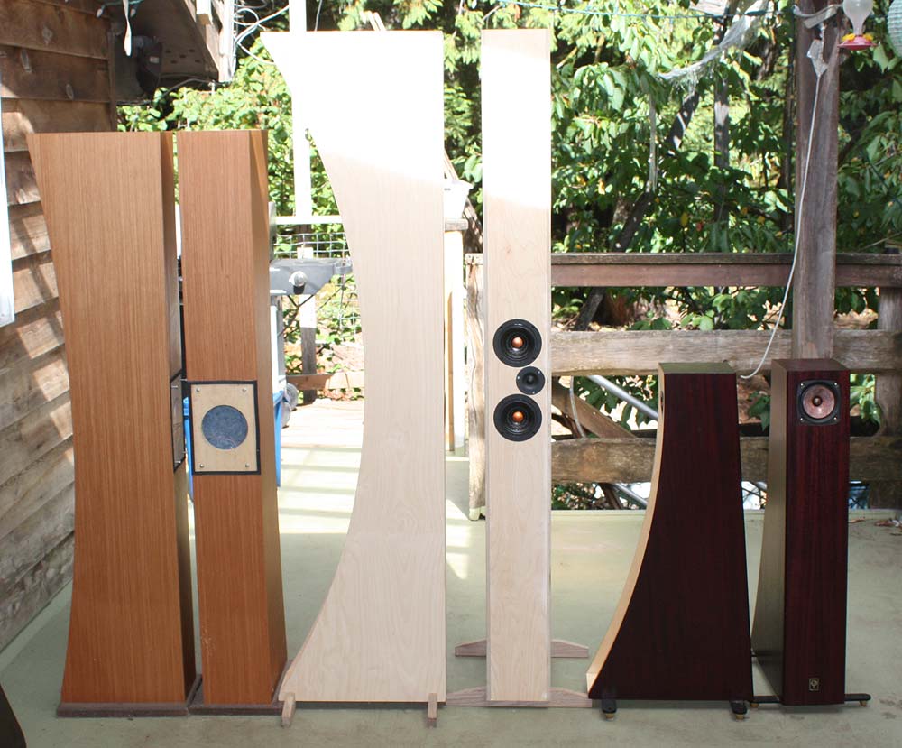
The middle image is not a Voigt (it is a bit more complex variation of a tapped horn) and one is stacked on top of the other (making it easier to keep the drivers at the right ear level), but illustrates the idea.
dave
The middle image is not a Voigt (it is a bit more complex variation of a tapped horn) and one is stacked on top of the other (making it easier to keep the drivers at the right ear level), but illustrates the idea.
dave
Thanks guys! And yet, what happens to the ripple when two drivers are present? Is there a benefit versus a single driver or a drawback?
The ripple should be smoothed out a bit as each bass driver excites slighly different sets of harmonics. You should still take advantage of mass-loading.
dave
dave
Thanks guys! And yet, what happens to the ripple when two drivers are present? Is there a benefit versus a single driver or a drawback?
=
the nominal point of excitation is at the centre between the two [mid]bass drivers.
Assuming you're placing the drivers reasonably close together, as is almost certain to be the case in an MTM, the above holds. The line 'sees' for practical purposes a single unit, so you place the centre point between the drivers at the target tap location. Job-jibbed.
Last edited:
My MLTL MTM at this address demonstrates my suggested way to handle the location of the tweeter and other design details:
The Triton MTM Grows Legs--A MLTL Design
In this example the tweeter is located down 1/5th wavelength down the line. Notice how the tweeter location is positioned for optimal listening height. The small tweeter diameter also permits closer mid-bass spacing in this example.
The Triton MTM Grows Legs--A MLTL Design
In this example the tweeter is located down 1/5th wavelength down the line. Notice how the tweeter location is positioned for optimal listening height. The small tweeter diameter also permits closer mid-bass spacing in this example.
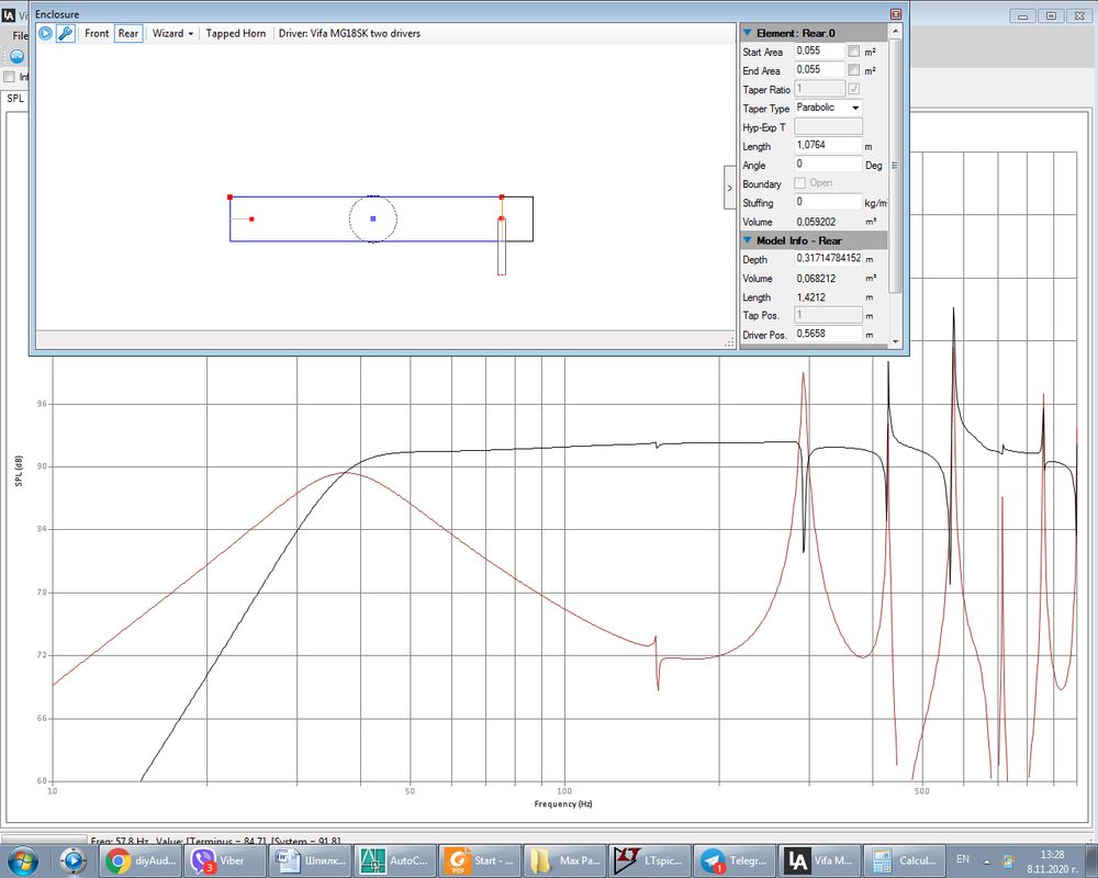
Playing with Leonard audio sim program, ML-TL
Hi again folks,
What is your opinion of the accuracy this software? I'm playing with paralleled Vifa MG18WK to make an ML-TL.
As far as I know, one of the benefits to make it mass-loaded is to reduce pipe length. But what should be the resonance of the pipe ratio vs the port tuning ratio?
So I decided to experiment by adjusting the pipe length to resonate to the double of the desired frequency, which is roughly 38Hz, so the pipe resonates at 76Hz. The rest is done by the port.
Should this be equal to 50% pipe to 50% port tuning?
The closest parasitic harmonic is attenuated at 0.46 speaker placement. And the pipe area seems to work best at 2xSd. At further increasing the pipe area there's the distinctive LF saddle occuring.
By playing with the port offset, I was able to achieve this response. Keep in mind the speaker is unstuffed.
My my final question for now is - when moving the port closer to the speaker, do we lose the quarter wave resonance effect and move to a classical vented effect?
Thanks!
There is no proscriptive 'it "should" be xyz' as such. In practice you use what best suits your particular requirements. The shorter the pipe / main enclosure, the more forcing from the vent it requires for a given Fb. By and large, I would prioritise ensuring your tweeter is at ear-height & work around things from that point.
Last edited:
Yes, good point.
So one should focus on outside design criteria, such as speaker-to-ear location and placement? This is the kind of flexibility an ML-TL gives?
Best regards!
So one should focus on outside design criteria, such as speaker-to-ear location and placement? This is the kind of flexibility an ML-TL gives?
Best regards!
Not necessarily, just that good design mandates you consider all criteria rather than just one. The 'best' box load in the world isn't much use if you sacrifice a large number of other important factors to achieve it. So you pick your compromises and do what you can to balance things out. MTMs are rather directional, vertically for example. Especially if you cross where most people cross (as in 2KHz or >). So you need to get your tweeter at or close to seated ear-height for the intended application.
In my room, when seated my ear height is about 35in - 36in from the ground. So quickly using the factory driver data for the MG18WK09-08 as an example, and assuming 0.5ohm series R in circuit to account for typical wire loop, connection resistance, something like this would be a 'practical' MLQW of modest height:
L = 45in
CSA = 108in^2
Zd = 10in
Zv = 38 1/8in
Dv = 3in
Lv = 4in
Lag all internal faces with 1in OC-703 acoustic fibreglass board or equivalent rockwool, SAE-F10 wool felt, jute carpet underlay, or possibly ultratouch recycled denim.
Approximate tunings:
Fb = 29Hz
F3 = 32Hz [nominal anechoic]
F6 = 27Hz [nominal anechoic]
Last edited:
Isn't the MTM idea to minimize lobing, especially when using a low cut-off frequency? Although it will be hard to achieve a 1/2 lambda of the distance between the two mid woofers, I will be able to make a 3/4 lambda cut-off. Will be using a wave guide to load the tweeter.
It does to a point, but it's still more directional on the vertical than the horizonal axis. If you're waveguide loading and running a low XO frequency of c. 1KHz or < then you have more flexibility, assuming in the process you don't say fare thee well to the HF. 😉 All other things being equal, I'd still recommend having the HF driver at typical ear-height for the application, if possible.
I suggest that you read message #11 about my design implementation dimensions and resulting performance. I chose the length of the line (essentially the height of the cabinet), placed the center of the MLTL at ear level, and moved the three drivers 1/5 th wavelength down the line. The result was a modest size floor standing speaker that was easy to build yet yielded great performance.
As Scott has related--via his posts--the design balancing act involved in generation of a MLTL. Having a simulation capability helps to evaluate these options and enables you to finalize your speaker.
As Scott has related--via his posts--the design balancing act involved in generation of a MLTL. Having a simulation capability helps to evaluate these options and enables you to finalize your speaker.
Hi Jim,
Not sure if it made sense to me. You have adjusted the tweeter at the desired ear level and then you have adjusted the placement of the two midbass speaker to obey the 1/5 wavelength rule? So that the top one is placed at the 1/5 point and the second at the 2/5 point?
Best regards,
Alexander.
Not sure if it made sense to me. You have adjusted the tweeter at the desired ear level and then you have adjusted the placement of the two midbass speaker to obey the 1/5 wavelength rule? So that the top one is placed at the 1/5 point and the second at the 2/5 point?
Best regards,
Alexander.
No, Jim means he's got the tweeter on the 1/5 axial length location as that is the centre point for line excitation by the two midbass drive units in a close-spaced MTM configuration. The box I did above for a pair of the Vifa units has a similar relative location, albeit not quite the same; 0.222 axial length to be precise.
Last edited:
- Home
- Loudspeakers
- Multi-Way
- MTM in a TQWT type enclosure?