Radical Tweeter Capacitor...
This thread was split off from here: The "Elsinore Project" Thread - Page 46 - diyAudio
LET'S GET RADICAL - THE RADICAL TWEETER CAPACITOR
This is the beauty of DIY, please read the following as it is an optional add-on to the Elsinore design.
I have stated previously that I reckon the series capacitor to the Tweeter, the so-called High-Pass filter capacitor, is the single most critical crossover component (not that the others remain unimportant). There are some fairly unknown (generally speaking) reasons behind this and here is the first time I have actually stated more precisely the reasons for it.
Research has shown that THIS capacitor is prone to nonlinear distortions and particularly of the IMD (intermodulation distortion) kind. When capacitors directly in the signal path sees an AC signal that traverses zero Volt DC - and that is really what AC does - the distortion is primarily odd order (bad kind), but if the same capacitor is
biased DC wise, then it becomes more even order (sweet kind). We know that if we have to choose between those we'd take the latter any day.
What this means is that capacitors directly in the signal path will sound better in most amplifer circuits where it is used to block DC, such as in tube amplifiers, BUT... when it comes to speakers, there is no DC and hence in speakers the very same capacitor will potentially sound worse.
Since we don't want DC in our speakers, we really are stuck with a bad situation.
Or are we?
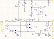
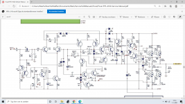
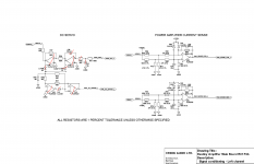
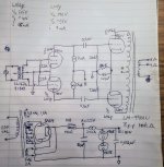
Take a look at this:
BEFORE: Shows the current crossover.
AFTER: Shows the same crossover in-so-far that the series capacitor has the same 4.7uF value when the series-parallel configuration is taken into account. Then the crossover function is exactly as before.
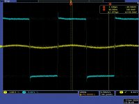
So what is going on here. Simply the 9V battery (should be new alkaline and about 9.5V) available at just about any corner shop, biases the coupling from the centre outwards. Without any signal to the Tweeter, both sets of caps see the same 9.5V across it. This is because it is 0 Volt DC on the other side of both caps.
When an actual AC signal (music) comes along, when positive, the voltage will swing upwards above the 9.5V and there will be
no celing and when it goes negative, it will eat into the 9.5V of the battery. So the available voltage swing where DC remains across both side (caps) is +infinite/-9.5V - or put is another way, it is able to swing 6.7V RMS before the bias (not the signal) clips on the negative side.
Now can you guys understand why I like and recommend external crossovers (easier access)?
PARTS: You will need to quadruple the number of your 4.7uF caps, although you could also use 10uF - but the result will be 5uF instead of 4.7uF, so you might perceive a little more energy in the presence region. The 100K resistor should be a good quality 1 Watt type. The battery should be a long life alkaline type. The resistor limits current to 100uA pretty much all the type. A couple of battery snaps/wires that clips onto the batttery.
BTW, you could double up on the battery and get an effective 19V DC Bias. Whether that would be audible probably depends how loud you like music? Haven't tried, only 9.5V.
How long will the battery last? Almost certainly for years and close to its shelf life. Just check its voltage from time to time.
I am not going to tell you in advance about any sonic gains. I don't want to telegraph your reactions and I want them to be fresh and in your own words.
SO WHO WILL BE THE FIRST CAB OFF THE RANK?
Joe R.


