I'm planning on building two H-frame (sub)woofers - tomorrow😉 - with dayton audio rss390ho-4. I bought the drivers for sealed subs, but dipole might chime in better with my dipole main speakers.
They'll be crossed quite high (80-100hz) and I'm mainly interested in great bass quality, not in lowest sub-bass.
Two opposing schools AFAIK:
- dominant one being high qts & low xmax (alpha 15 et al)
- low qts & high xmax & heavy eq (Linkwitz, 'My open baffle-less speaker journey' etc.)
Since I have power and dsp in the form of Behringer NX3000D, I figure the daytons would work in H frames (c. 17x17x15").
Any thoughts?
Simon
Last edited:
Once equalized to the same target response, they will have identical impulse and phase responses.
High Qts and high fs requires less equalization in open baffle and therefore less amplifier power. It might even do without active equalization at all, making a passive crossover feasible in a 3-way loudspeaker.
A low Xmax is associated with open baffle, because PA woofers have a high efficiency in an open baffle, but do have a lower Xmax than hi-fi woofers.
The RSSxxxHO woofers are designed to be put in small closed enclosures. As a result, they have a heavy cone, low efficiency and are expensive. There is no reason you cannot use them in an open baffle, they just are not optimized for it and there might be cheaper woofers available which perform better in an open baffle. Moving the 0.3 kg cone back and forth transmits strong vibrations to your floor and might annoy your neighbours. Check if the magnet vent does not chuff at high excursion.
Last edited:
Yes - its true - a high Q driver will need less power for same sound pressure. But how? Well due to that the high Q driver becomes a resonant system (anything with Q over 0,5 is) so efficiency is traded for fidelity. Booommboombomm instead of bom.
//
//
Hi Simon,
If you have the power and DSP, it will work. With the high Mms they´ll shake any wooden H-frame massively, so you might think about building the frames in concrete or, more feasable, consider sand-filled sandwich panels for your H-frame.
Good luck and all the best
Mattes
If you have the power and DSP, it will work. With the high Mms they´ll shake any wooden H-frame massively, so you might think about building the frames in concrete or, more feasable, consider sand-filled sandwich panels for your H-frame.
Good luck and all the best
Mattes
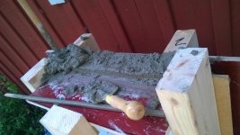

Thank you all so much! You've made me change my mind (again). The vibration issue was new to me: concrete is out of the question, and no energy for building sandcastles atm...
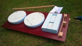
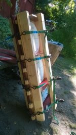
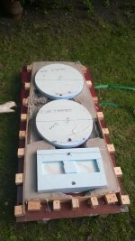
Back to plan A (already at the assembly stage): sealed enclosure using steel ventilation tubes, mdf end plates, threaded connection rods and bitumen covered inside walls.
Sooner or later I WILL hear a kick drum reproduced as it truly sounds........ 😱
Simon
Back to plan A (already at the assembly stage): sealed enclosure using steel ventilation tubes, mdf end plates, threaded connection rods and bitumen covered inside walls.
Sooner or later I WILL hear a kick drum reproduced as it truly sounds........ 😱
Simon
Concrete is THE subwoofer material. I build two and they both sound a lot better than any kind of MDF or wood. Concrete stiffness and high weight makes a strong subwoofer feel really good. Its worth the effort, but I used carbon fiber concrete, its very very good for this purposes.
If you want to experiment with open baffle, consider building a W-frame. Opposing the woofers in the same enclosure / open baffle frame will greatly reduce cabinet vibrations.
You can increase the sensitivity and lower fs AND get higher Qts by modifying the spider.
I have done that with JBL 2226H. I cut small pieces out of the spider, and made tham perfect for OB! Or IB...
I have done that with JBL 2226H. I cut small pieces out of the spider, and made tham perfect for OB! Or IB...
If you want to experiment with open baffle, consider building a W-frame. Opposing the woofers in the same enclosure / open baffle frame will greatly reduce cabinet vibrations.
Thanks TBTL, that's the route I would take if I had 4 of them. But I won't find another 2nd hand pair in the Unites States of Belgium (USB).
Once equalized to the same target response, they will have identical impulse and phase responses.
High Qts and high fs requires less equalization in open baffle and therefore less amplifier power. It might even do without active equalization at all, making a passive crossover feasible in a 3-way loudspeaker.
Just wanted to drop a note about power for LF drivers used like this. While it is true that a lower Q driver will need more "lift" before the amplifier (line level voltage) the actual power requirement may be LESS in some circumstances.
This topic came up awhile back and I was in the camp that high Q drivers will always need less power because they will need less EQ/boost/lift at high frequencies. But I forgot to consider the load. The driver has a variable reactive load and the magnitude of this can actually be lower below Fs for a high Qts driver, which will draw a lot of current. In contrast, a low Qts driver has, because of its very broad impedance peak around resonance, an impedance much above Re until you get away from Fs. With very low Qts drivers (e.g. 0.2 and less) you have to get almost an octave away before impedance drops close to Re. The result is less actual power is drawn by the load in this region even though there is a higher applied voltage. You will best see this in a TS simulator if you take a known driver and make the other kind from it by changing Qe or the like. Until I did this I did not believe that this really was true.
In the real world each driver is different in terms of its near resonance properties, so you need to individually evaluate how much actual power will be required for your application with a given driver. Sometimes a low Qts driver paired with a PA amp is a winning combination for an OB. Not always. Keep in mind that your amplifier may seem to have enough "power" but the large amount of current that is needed when lots of boost is applied may exceed its capabilities. Again, it pays to check these things out when designing your system.
SL created a useful Excel (XLS) spreadsheet for these kind of what-if scenarios, which I am attaching. The forum software does not allow uploading of excel files, so changed the extension to TXT so that the upload would be allowed. Change the extension back to XLS before opening the file.
Attachments
It also serves to mention that most amplifiers are actually VOLTAGE sources. Any line-level equalization done to the signal driving the amp changes its output voltage, and for each amplifier there is a limit to how high that output voltage can be.
The POWER consumed depends on the load that the amplifier is trying to drive.
An amplifier can be driven into clipping without it exceeding its output power rating if its output voltage capability is exceeded when trying to amplify a boosted signal.
The POWER consumed depends on the load that the amplifier is trying to drive.
An amplifier can be driven into clipping without it exceeding its output power rating if its output voltage capability is exceeded when trying to amplify a boosted signal.
Thanks, good information.🙂Just wanted to drop a note about power for LF drivers used like this. While it is true that a lower Q driver will need more "lift" before the amplifier (line level voltage) the actual power requirement may be LESS in some circumstances.
- Home
- Loudspeakers
- Subwoofers
- Sanity check: 0.3 qts in H-frame