Fisher 400 Oscillation

Hey folks.

I'm repairing a Fisher 400. Customer wanted new 7868 bases - done. I've replaced the filter caps with the Hayseed Hamfest excellent replacement set - fine and dandy so far. Voltages all fine.

However, I'm getting an oscillation when the PI and power valves are inserted (can even by one PI valve and one 7868):

IMG_0173 copy.jpg


Here is the relevant section of the schematic, have attached the whole thing hopefully:

Untitled.jpg


Oscillation goes is the PI valves removed or the power valves are. It builds up as the valves come into emission. Theres a 1200 ohm 10W resistor which drops the HT down to the screen node which then goes off the other rest of the HT, the voltage drop without the oscillation is about 25Vdc, when both the PI adn power valves inserted that voltage drop goes to >100Vdc. I thought a short but cannot find one, even isolating other parts of the circuit.

I've rebuilt one side with new components - no help

There was a thread:


Which mentioned droping the grid leak resistors from 330k to 220k and increase coupling cap value from 0.47 to 0.1-0.2uF to account for newer valves

Feel like I'm missing something obvious but going slowly mad at same time. Anyone think those mods will help? Also wondered about adding in dedicated screen resistors for each output valve?

thanks for any help

Attachments

6L6GAY for sale

Brand new NOS/NIB Sylvania 6L6GAY beam tetrode tubes/valves/Röhren. As all good stuff comes in uneven numbers it is a lot of 5. All new, never have been powered up except when they were produced. The boxes are worn because of me wanting to look at beauty the past 3 decades. There, I admitted it.

Good stuff apparently made by an early LHBTQI+ community in 1951 in a factory where devices were produced that brought peace and democracy.

If you want these then make me an offer I can not refuse by PM. No tube tester here but it is very likely that JAN stuff was made according specifications and also to last. No guarantees but I do guarantee they will be packed very well and definitely shockproof. These just wait to be used in a nice design. 73 Years old but new/unused tubes and no Chinese knockoffs with fantasy names made of recycled refrigerators, these are truly the real deal made of pure materials. By virgin angels in moonlight. You will have a veil unlifted and blacker than black background 😀

EU ONLY!

Attachments

  • IMG_7971.jpg
    IMG_7971.jpg
    117.2 KB · Views: 116
  • IMG_7972.jpg
    IMG_7972.jpg
    44.6 KB · Views: 123

100 year old amplifier.

As tube technology gets old I thought it might be a idea to produce a Hi-Fi tube amplifier using components and technologies that were available 100 years ago.

Maybe a competition, the prize, the glory of doing it.
The rules, let us all make them up.

My ideas:

Capacitors, resistors, transformers were all about 100 years ago so they may be used.

The UX250 audio power triode was introduced in 1928 so it may be used in a build for 2028.

The UX245 was available in 1929 so any type 45 even a modern production could be used in a 2029 build.

The UX201 was introduced in 1925 so any 01A type could be used in a 2025 build.

The 6L6 was introduced in 1936 so it could be used in a 2036 build.

The speakers are not part of the amplifier.

The power supply is not part of the amplifier as batteries were about.

Spice sims allowed in the simulation class.

I personally have some 45's and 01A's so the best I could do is a 92 year old build, maybe I could scrape a year or two off it.

Spice sims allowed in the simulation class.

Ken Kranz
Australia

For Sale Elna for audio, Silmic, RSE capacitors

1730552786125.jpg
1730552759434.jpg


I have here for sale severall capacitors from Elna new and used.
1-Raw
Used Elna Silmic 12000uF 63V 20€/unit or all 4 for 60€
Used Elna for Áudio 10000uF 63V 12€/unit
Used Elna for Audio 10000uF 63V 12€/unit
2-Raw
Used Elna Silmic 5600uF 63V 10€/unit
Used Elna for Áudio 10000uF 56V 10€/unit
New Elna for áudio 10000uF 25V 5€/unit or all 6 for 24€-sold
3-Raw
Used Elna for áudio 3900uF 63V 5€/unit
Used Elna for áudio 3300uF 35V 2,5€/unit
New Elna for áudio 10000uF 25V 5€/unit or all 6 for 24€-sold

New Elna RSE 2.2uF 50V 20units per lot at 10€,10 lots available(200 units)
I can sell the whole lot together for 200€ "230 capacitors"
All used capacitors here for sale have been measured and are within 10% of its rated capacitance

Regards

Attachments

  • 1730552759428.jpg
    1730552759428.jpg
    552.1 KB · Views: 143
  • 1730552786117.jpg
    1730552786117.jpg
    480.4 KB · Views: 126
  • 1730552786108.jpg
    1730552786108.jpg
    582 KB · Views: 123
  • 1730556954655.jpg
    1730556954655.jpg
    450.4 KB · Views: 120
  • 1731159254236.jpg
    1731159254236.jpg
    445.2 KB · Views: 109

Passive cardioid MTM(W) Speaker

Hello,
I'm planning to build my first pair of DIY speakers as an complement to my current Klein+Hummel O300D + 2x Adam Sub10 Mk2 setup. I mainly use them for mixing and post-production, but I'd like to do more mastering in the future and therefore I want a second (hopefully "better") set of speakers.

Since most mastering speakers are way out of my price range, I thought I try to build a good set of speakers myself. The last few months I gathered information about speakerbuilding and found many helpful posts on this forum, so I'd like to share my plans with you.
I'd be grateful if someone could point out some mistakes in my design or things that could be improved!

My design is mainly inspired by speakers like Egglestonworks - "Viginty" and "Kiva", Amphion - "Krypton³" and Lipinski "L-707".

I want to imply following features:
a) MTM/D'Appolito Satellite (maybe with a passive cardioid like the Krypton)
b) TL or vented Sub, high enough that I can put the satellit on it and have the
tweeter at about 115-122cm (my earlevel), but in a separate box to have
the freedom of experimenting with different room locations if the bass
response is not smooth enough at the triangle.
c) Drivers:
Mids: 6" Morel TSCM-634
Tweeter: Morel TSCT-1044 with Waveguide (Visaton WG148 or Monacor
WG-300, I'll have to test which fits better)
Bass: 10" Scan-Speak 26W/4867T00
d) Active analog 3-way Crossover: I have the Rane AC23S, which has fourth
order Linkwitz-Riley filters and a delay up to 2ms for the low and mid
channels.
e) Separate amp channels for woofer/mid/tweeters. At the moment I have 2
PAS 2002 PCA Stereo amplifiers. But I need at least 1 more (if not different, more powerful
amplifiers). This is one of the points where I am not sure about.

Completed the PH-16 Preamp

Around 4-5 months ago I got the PH-16 kit from Tubes4HiFi – and started putting things together. Attached are the results.

It was a challenge, especially getting parts to the bottom of the planet (Auckland - New Zealand), but I got there in the end. The amp sounds amazing – wide soundstage, open separation, punch at the bottom end and clarity at the top end. I’m running it from my Rega Planar with Ortofon cartridge into a Cayin A88T power amp - heavily modified with Mundorf caps, and Gold Lion KT-88’s among other things. As an aside, I’ve found the Cayin amp to be awesome. Extremely high build quality, much better than some amps I’ve seen at 3 times the price and the circuit design is simple and robust.

The PH-16 is a great design, and I added Mundorf caps and Gold Lion tubes. There is very little hum as I placed the transformer above the aluminium mounting plate well away from the signal board. One of the challenges I had was to fit the volume control at the output of the circuit. I managed this with a Ladder Stepping Attenuator (Dale resistors) and this seems to work OK, although I haven’t quite got the linearity required, but I’ll experiment.

My family will now be subject to large amounts on Pink Floyd, Mozart, and the occasional Iron Maiden experience.

Attachments

  • 20250126_142734.jpg
    20250126_142734.jpg
    80.9 KB · Views: 61
  • 20250126_142742.jpg
    20250126_142742.jpg
    77.2 KB · Views: 60
  • 20250126_142753.jpg
    20250126_142753.jpg
    60.5 KB · Views: 62
  • 20250126_142805.jpg
    20250126_142805.jpg
    76.3 KB · Views: 70
  • 20250126_150058.jpg
    20250126_150058.jpg
    67.2 KB · Views: 66
  • 20250126_150129.jpg
    20250126_150129.jpg
    54.8 KB · Views: 62
  • 20250126_150146.jpg
    20250126_150146.jpg
    76.2 KB · Views: 57
  • 20250126_150207.jpg
    20250126_150207.jpg
    62 KB · Views: 71
  • 20250126_101208.jpg
    20250126_101208.jpg
    65.1 KB · Views: 64
  • 20250126_104438.jpg
    20250126_104438.jpg
    77.7 KB · Views: 68
  • Like
Reactions: gerrittube

Copy of catalog / plans for a transmission line loudspeaker kit from Accurate Sound, Lincoln NE, circa 1977

In 1977 I built a pair of transmission line loudspeakers, similar to the famous Webb design, but somewhat larger. When I went to graduate school in 1980, they were too bulky to bring along, so I sold them. Now, both myself and a friend from those days want to build a couple of pairs. So I'd like to locate a copy of the plans.

With that as an intro, does anyone here have a catalog or plans from the company that produced the kit? It was called Accurate Sound, and was at 1213 M Street, Lincoln NE 68508. Below, I've reproduced a copy of an advertisement of theirs, from the January 1977 issue of Audio Amateur, page 49.

IMG_2910.jpeg


Does anyone here recognize this, or have an old catalog or plans?

Cheers,
Bruce

Best Car High End Amps You Have Tried

I wanted to see if someone had real world experience and can rank the top ten amps they have actually tried. For example Brax, Sinfoni, Celestra, Steg, Audison, Arc Audio, Mac, Linear Power, Genesis and TRU Technology...the real high end.

It does not make sense these days to waste your time putting an average system in a car, do it once and do it right.

Also do you prefer regulated vs. non regulated

Falcon Acoustics B139 B110 T27

Has anyone bought any of these?

I have been trying to get some measured data on these Falcon drivers for many weeks now, without success. Multiple emails requesting information have been met with vague, terse and evasive responses from the owner Jerry Bloomfield. His replies have lead me to believe that these drivers have never actually been measured under any kind of realistic conditions (eg. IEC baffle), not even in prototype form.

Having used the KEF originals many years (decades) ago, I am genuinely interested in how the new versions perform, but the lack of cooperation from Falcon has been extraordinary.

Nice, new article from Bob Cordell on transistors in audio ...

Just a "heads up" that Bob Cordell wrote what I think is a pretty good article on transistors in audio. You can find it on the HomeTheaterHiFi site here.
Especially good for some of the newer folks that are coming in.

Thanks Bob - good job!

P.S. Moderators: I wasn't sure of the best place to mention this info. Please relocate if appropriate!

PS Audio 200c transformer specs?

Hi folks,

I recently moved to France, and I am looking to reconfigure my amps for 230V/50Hz. Most of the amps I have are restrappable (dual primaries), but the PS Audio 200c does not appear to be. This amp is very powerful - it's nominally 200WPC into 8 Ohms, but keeps doubling, up to 800WPC into 2 Ohms, and 1000WPC into 1.5 Ohms. But it does not seem to have a line fuse or a VA rating on the chassis. It's not UL rated either. They do have a bit of a reputation for pyrotechnics...

Anyway, it looks like dual 104VCT secondaries, with no other voltages. But I've no idea what this original transformer is rated for current. It was made by Paraline, who was very helpful 15 years ago, when I got the amp - they revarnished it to see if they could make it hum a bit less, which I think it did - but they seem to be out of business now.

Any information, or educated guesses?

Thanks,
Paul

Wharfedale Linton 2 Old Model

I have a pair of these. Cause I like lost causes I would like to refurb to a reasonable extent. To my ears classical music is nice and open and the stereo imaging is pretty decent.
If I was to do some checking, reasonable maintenance to keep any costs within the worry of these speakers what would you do?
The drivers are all pretty decent and everything on a visual check is as it should be......I think. 😜

How to Inject a Negative Noise Signal Directly Behind the Output Buffer of a High-Power Amplifier?

Hi everyone,

I’m working on a Amplifier 100W and looking to implement a system where I can inject a negative noise signal directly into the signal path after the output buffer, specifically between the output buffer and the speaker output terminal. The goal is to cancel out unwanted noise via destructive interference, without affecting the main audio signal's quality.

Here’s what I’d like to understand:

  1. Can I use capacitive coupling to inject this inverted noise signal into the high-power signal path?
    • If yes, what would be the appropriate capacitor value and voltage rating for this setup?
  2. Are there other methods (e.g., inductive coupling or resistive networks) that could work better for this purpose?
  3. What precautions should I take to ensure that this injection method doesn’t degrade the audio quality or interfere with the main signal's integrity?
Key considerations:

  • The amplifier runs at (100 W into 8Ω), so the components need to handle significant currents and voltages.
  • I’m trying to avoid transformers, op-amps, or any components that could introduce distortion or phase shifts or are not suited in terms of Voltage rating.
Looking forward to your insights and recommendations! If someone has experience with noise cancellation systems in high-power audio applications, your advice would be invaluable.

Thanks in advance for your help!

Dreams

My dreams are always about solving some problem. Never "drifting, falling, floating weightless, coming home" or "Let's break out the booze and have a ball". Always some problem to solve. This morning was a big wind is coming, most danger from flying debris. Get underneat the house? Inside cars in the garage (what if the door tears off?) Inside the small truck downstairs in the RV garage? Better act quick, outside exposure is dangerous! No matter how arbitrary, abstract, disconnected from current reality, the problem solving aspect is always at the core. Anyone else?

Selling speakers and chassis

Hello folks,

Due to current events, I would like to hear about your experiences with selling DIY speakers.

My initial research (here and in the neighboring forum) shows that the market for DIY speakers looks even worse (from a seller's perspective) than it did 5 or 10 years ago. Lots of high-quality chassis and speakers are practically thrown at you

While others are no longer available, like the Monacor WG300 and DT300.

What are your experiences?

Long-time audio nut, new(ish) to DIY

Hello All,

Just to briefly introduce myself, I’m currently living in the UK, but have also lived in Europe. I’m a screenwriter and film-maker by profession and have been passionate about audio since my early teens.

After moving on from my Dad’s simple all-in-one record player and speakers in the 70’s, by the early 80s I had my first hi-fi, which was a Dual CS505mkii turntable, Denon PMA-250 amp and Monitor Audio RS252 speakers. I thought it sounding fantastic and I’ve never looked back!

I’ve since run everything from full analogue to high end digital, including DSP speakers, full surround systems and purist 2-channel setups. I’ve spent thousands on cables (and would not do so again!) and learned more than I need to know about room modes!

My first “DIY” projects were building a solid state amp from a kit, and removing balance pots (replaced with suitable resistors) from a Naim preamp.

I’m now interested in taking matters into my own hands by building some valve amp (and preamp) kits and making my own speakers. For the learning and fun, and to try and get a sound I love even more.

All the best.

I Need Help, PLEASE!

Hi Everyone, To make a very long story as short as possible, I bought a Soekris DAM1021 v1.1 on February 1, 2015. Due to many moves, and very little free time, the project was "lost" in one of our hundreds of boxes for almost 10 years, until the other day when it was "found"!

I have the main Soekris Board, as well as a Normundss Input Board, Front Panel Board, an STM32 Board, a USB Board, and some hardware.

Can anyone direct me to a complete build thread, or at least a parts needed list, in addition to an appropriate enclosure that can be used?
Your help in completing this long overdue project is greatly appreciated!

Roger

IMG_20250127_162900_706[1].jpgIMG_20250127_162928_016[1].jpg

An admirable attitude toward the "reddit" platform

I found this commentary on the Reddit platform striking. Parallels here, in the context of Audio and DIY?

[–]PackOfWildCorndogs 4 points an hour ago

I feel the same, I love being forced to reconsider my opinion or perspective, and that’s something I am regularly pushed to do on here. Spending time on Reddit over the years has increased my empathy for, and understanding of, the experiences of people with different worldviews than me. Less quick to judge, more tolerant in general. Plenty of complaints and fully aware that you can forget it’s an echo chamber itself sometimes, but I think my time is much better spent here engaging in, and reading, (mostly) civil debate with people who think differently than me, and have had vastly different experiences than me.

I lurk in a lot of subs that I don’t engage with, because they neither need nor want my thoughts, but reading their thoughts and debates helps me be a more informed fellow human with a more tolerant worldview. I wouldn’t otherwise be exposed to these groups organically in my day to day life. It’s also helped me to become a more discerning and skeptical news consumer — reading some of these conversations helps give some nuance to headlines and the claims they contain. I can go to some of th subreddits where I know the group or event referenced in the headline likes to congregate, and almost immediately I can see where the headline is sensationalized, or the motivation behind it (positive or negative), by reading the conversations of the people involved or affected by the event. Again, not perfect, but it’s a really effective way to add some depth and texture to the topic, beyond just the news as it is being reported.

Aside from being an endless source of satisfaction for intellectual curiosity, some redditors are funny as ****. Little unexpected bursts of dopamine/laughter in the comment sections isn’t something I can regularly expect in comment sections on Instagram, which usually only leave me feeling a tinge of deflation seeing the lack of critical thought and hardcore tribalism, with zero nuance or effort at coherence. Reddit upvote system isn’t perfect and it’s easily manipulated by users and mods, but the highest effort, most thoughtful, valuable comments are often the most visible, so I feel like even my time spent is more efficient on here than in the comments of platforms like TT & IG, where there is no rhyme or reason to the most visible comments, and more concerningly, where the comments that are most visible to you are dictated by the algorithm.

For example: My mom (right leaning views) and I (left leaning views) looked at the same Instagram post with thousands of comments, at the same time, side by side, from our own phones/IG accounts, and the comments that were visible to her were entirely different than the comments I was being shown. The algo exists to reinforce your echo chamber over and over again, by serving you the content and comments that the algo has determined you’re most likely to engage with. Two people looking at the same post, at the same time, in the same physical location, are having two entirely different (and oppositional) user experiences. It’s a bit disturbing, even when you know why it’s happening. And yes I’m aware Reddit algo does similar, and has of issues with brigading and bot manipulation, but at least I can see all of the comments if I really want to. On other platforms, it’s not as easy to see the full spectrum of comments when you want to.

Music fidelity A5 intergrated amp SAP15 transistor modification

Hi all, got myself a MF A5 intergrated amplifier thats using the sap15 transistors.
These transisitors have the emitter resistor built in and are prone to failing. Ive read that you can lift a leg on these transistors and put your own cement 0.22ohm resistor in its place.
Question is can anyone advice what leg to lift and where to solder new resistor please, or any pictures of this done or drawings would be fantastic!

Thanks inadvance
Richard

Audio System X-Ion 280.2 bias issue?

Hi guys,

I have a weird issue with an Audio System X-ION 280.2. It similar to audio_system_f2-190 in the attached pdf, but not exact. I've used those schematics as a referance.
There is crossover distortion once You apply any load to it. Goes for both channels. If there is no load applied the sinewave behaves differently. There is distortion on the bottom half and the top half is being chopped off.

Rails are exactly the same and correct +-50v, +/- 15 are present, There seems to be some issue with the bias, at least to my understanding, but using the bias knob make little to no difference, there is almost no increase in current draw between min and max position. And i've repaired amp like this before, this is not correct behaviour.

I've changed already the LL4148B diodes and the Zeners but with no avail.

Any idea what can cause this issue for both channels at the same time ?

Attachments

  • Load 4 ohms.jpg
    Load 4 ohms.jpg
    269.9 KB · Views: 68
  • no_load.jpg
    no_load.jpg
    243 KB · Views: 64
  • X-ion.jpg
    X-ion.jpg
    412.4 KB · Views: 72
  • zeners.jpg
    zeners.jpg
    384.2 KB · Views: 70
  • zeners1.JPG
    zeners1.JPG
    46.2 KB · Views: 71
  • audio_system_f2-190.pdf
    audio_system_f2-190.pdf
    826.8 KB · Views: 41

With so many fake TPA3118 boards (eBay etc), is it still possible to even buy a working 60w board in 2024?

In 2020 it was no problem to buy these TPA3118 boards for like $4 each. They sounded decent and put out about 50w mono at 24VDC / 3A supply.

Now, every one I order has 28 pins instead of 32 and is a fake. The power is less, and half the time the fake (faulty) board will put out DC on the speaker output (fried one 6x9 in this way).

Before these counterfeits hit the market, this was a nice little amp board for almost no money. Are they still available anywhere or are those days gone?

Is there a better option at 12 or 24 volts supply?

Help with crossover for Living Voice clone

Hi,

please critique my first attempt at a crossover for a Living Voice Auditorium clone I'm working on.

The speaker is a 2-way MTM with 2 x Vifa C17 6.5" midwoofers and initially a Scanspeak D2608/93000 tweeter. I got better measured response with Morel CAT 378 tweeters, so I used those in this simulation. I measured all drivers according to the Vituixcad procedure, however I only have on-axis response for the Morel since I just got it. So I have to leave out power response and directivity for now. The last image shows the response of the drivers without filter, for reference.

I'm a little wooried about the broad overlap area between 2khz-5khz, is this any reason for concern? I think the phase tracking in this area looks pretty good though.
Also would the large impedance hump centered around 3khz cause any issues?

Attachments

  • config.JPG
    config.JPG
    27.2 KB · Views: 535
  • spl.JPG
    spl.JPG
    70.7 KB · Views: 316
  • phase.JPG
    phase.JPG
    62.1 KB · Views: 216
  • impedance.JPG
    impedance.JPG
    45.5 KB · Views: 221
  • raw response.JPG
    raw response.JPG
    68.6 KB · Views: 310

DIY B&O MMC20 replacement with OM Cartridge Generator

I bought a BEOCENTER 2000 stereo system (Made in Japan) with the intention of further developing my idea of replacing the B&O cartridge(s) with an Ortofon OM series cartridge. Compared to the MMC20, the OM series specifications (stylus pressure, compliance, etc.) and generator size are somewhat similar, so a replacement might be possible. And the generator can be removed from the plastic part of the OM cartridge by simply pressing.

I made a quick 3D model of the new cartridge holder (it does not have the exact offsets, angles etc):

DIY B&O Headshell.JPEG
IMG_0520.JPEG

IMG_0578.JPEG
IMG_0579.JPEG


This actually turned out to be looking quite ok.

BUT: this modification would be irreversible, so you would have to break or replace the whole original tonearm tube. And I had the (positive) problem that the cartridge and stylus that came with the system I bought turned out to be still in good condition, so I didn't feel like continuing with the cartridge replacement.

So this is more of an idea that someone else could continue with...
  • Like
Reactions: alighiszem

Is there any benefit in adding an aluminium shield in my phonostage?

I built myself a BB3 phonostage, initially in a relatively small box, but suffered a bit of hum from time to time.
Recently, I decided to rehouse it into a bigger case, which is pretty much finished now - see below.

I am wondering if there would be any benefit from fitting a 5mm thick aluminium “shield” Between the BB3 PCB and the mains related side of the case. It will not be expensive to do, or take long, but will there be any benefit?

PXL_20240802_143630763~2.jpeg

Acoustic Horn Design - The Practical Way

It was suggested to me to start a thread regarding the actual practical builds of horns and waveguides, mainly designed with the Ath. So here it is, for everyone to share their own way of converting their design into something real and listenable. Show off! 🙂

So far the tool can generate:
- STL file,
- coordinates files to be imported into Autodesk Fusion 360 as splines and/or smooth surfaces.

There may be other useful features implemented in to tool to enhance the practical possibilities - just let me know.

RLC measurements with an AD5933 eval board

I bought an AD5933 eval board some time back to facilitate measuring capacitors and inductors. I just got around to actually fooling around with it (using an Arduino Uno) and initially had some problems. While the calibration procedure seemed to work OK (I used a 100K resistor for that), results for different-value resistors and capacitors were WAY off. I thought there was a problem with the driver code, which I downloaded from github. I thought perhaps there was a problem with the board, like a cold solder joint.

But it turns out that the code and board are OK. The main problem was that I was using the maximum-gain setting for the input amplifier so the AD5933's ADC was overloaded.

Once I figured that out I was able to get much-more believable resistor and capacitor measurements. In turn, I measured the capacitance of my headphone cable, to build a load tester for DIY headphone amplifiers. 200pF will do it!

I just recently checked ebay to see what the current prices are for an AD5933 eval board. I found some in the $30-$40 range. However, for about the same price you now can buy a "component tester" that can test R's, L's and C's, but you also get the ability to test some active devices, too. So while the AD5933 eval board is a nice thing to have, i probably would have bought a component tester had that class of tool been available at the time.

NVArcher BP1048 DSP - output extremely quiet

Hello,
I recently purchased this small NVArcher BP1048 DSP Board.
It worked fine for the first two days, but when I came back the next day and turned it on, the output was extremely quiet. So quiet that it took me a while to realize it was even running. I did not make any changes in the software.

After opening the ACP Workbench software to see if any volume sliders where turned down, everything seemed to be fine. All the volume slider where roughly at +-0dB. I had to increase one of the volume sliders (PGA0 - Line_in_4_5) to +40dB (!) to get any proper output volume, but obviously this distorts the sound like crazy and still was not very loud.
nvarcher-too-quiet.JPG

I turned all of the "Audio Effects" off, to make sure I did not mess anything up there.
The board itself is running and the problem is the same in both AUX and USB Input mode. Also the same on both outputs DAC0 and DAC1. I tried using different input devices, different cables and different amplifiers, but the problem is always the same. As soon as I plug the DSP inbetween, it is extremely quiet.
I played around with selecting and unselecting a few things and experimented with some sliders, but without success. I tried to reset it to factory settings, but I feel like this did not reset anything. Visually I can not see any damages on the PCB itself.

Am I missing something? It seems weird to me, that it worked fine at first and instead of completely dying, it still runs, just extremely quiet.

For Sale Open Baffle lii song Pair Silver 10 + Pair W-15 Leonidas Build

I am regretfully selling an incomplete project of a Lii Song Leonidas build. This follows Leon Huijgen's plans from the Audio Dandy Website.
It includes Lii Song Crossovers, a pair of Silver 10 + a pair of W-15 drivers
Too heavy and awkward to post.
Pick up from Australia 3134.
$1400 or nearest offer.

Attachments

  • 20250105_123121[1].jpg
    20250105_123121[1].jpg
    306 KB · Views: 133
  • 20250105_123147[1].jpg
    20250105_123147[1].jpg
    301.3 KB · Views: 126
  • 20250105_125631[1].jpg
    20250105_125631[1].jpg
    376.4 KB · Views: 121
  • 20250105_123134[1].jpg
    20250105_123134[1].jpg
    357.5 KB · Views: 125

Has anyone used SBT-SERVICEMANUALS.com? Looking for a service manual for Marantz SA14S1

I've been looking for a service manual for the Marantz SA14S1 so I can figure out the output impedance(I've got a picky tube pre-amp which doesn't like anything over 200ohms single ended).

The above website is the only one I've found which has it available but the site seems kind of shady and they want a lot of personal information before letting you download the .PDF.

I found a manual for the SA15S1 but I can't confirm if it's the same design or not. I'm not sure if I'm reading it correctly but it looks like the output impedance is going to be 100ohm for the single ended outputs?

Thanks for your time!

1738083069926.png

LAMBDA TD-15X pair (used)

PRICE REDUCTION


Literally downsizing.

These originally drove my Tuba HT subs.

Pair of used Lambda TD-15x drivers available in Massachusetts, USA.

Currently mounted in TOA EV monitors (free if wanted at asking price)

$600 includes domestic shipping to contiguous 48 States.

Will ship to any verified PayPal address for actual freight costs.

20250128_183852.jpg
20250128_183808.jpg
20250128_183808.jpg20250128_183852.jpg

Attachments

  • IMG_20241111_161315337.jpg
    IMG_20241111_161315337.jpg
    617.5 KB · Views: 17

2-way and 3-way high efficiency driver suggestions for Troels TL speakers

Hello forum members,
I am new to this forum, but I already have quite some experience in building speaker boxes.
I now have three rooms to be equipped with 5.1 home cinema speakers, although the main "payload" is gonna be music.
Because of high cost associated with I decided to build the speakers myself. I need the speaker boxes to be universal enough to accommodate a few different drivers.
My choice for cabinets is: Troels Gravesen Ekta TL http://www.troelsgravesen.dk/Ekta-TL.htm for front speakers and
STUDIO-101-mkII http://www.troelsgravesen.dk/STUDIO-101-mkII.htm for rear speakers.
But I wanna make it clear that this is just a guidance for the construction/shape/size of the speaker boxes. It is not my intention to copy those designs.
So what do I want to make?
I like those designs of Troels, but the speaker drivers he uses are way out of my budget. So I am looking for cheap replacements.
But I like the concept of the boxes. His Ekta TL can be adopted as bass-reflex, TL can be shorten or extended easily.
So, I need a your suggestion of what cheaper drivers can be used in those cabinets. I can make some adjustments to the cabinets to accommodate other types of drivers. No problem. But I want the genera concept to remain the same. TL for the front speakers and BR for rear speakers, full bandwidth for both.
So for Ekta TL my initial choice is:
-SB20PFCR30-8, https://sbacoustics.com/product/8-sb20pfcr30-8-paper/ , the same fs as the speaker in original design, so no mods to the cabinet are necessary,
- mid range?
-DT-300 from Monacor, https://www.monacor.com/products/akcesoria--/glosniki--/glosniki-wysokotonowe-hifi-/dt-300/

For STUDIO-101-mkII:
  • sub-mid range ?
  • DT-300 from Monacor

I consider those two speakers as good enough quality for the money, and good enough for me. In Europe all those drivers are available for more or less 50 Euro. And I would set the budget for the speakers in that range, plus minus a few euros. I already build some speakers with SB20PFCR30-8 and I consider it a very good driver for the price. Very good. But I am open for suggestions here.

The requirements are (for both front and rear):
  • absolute minimum driver sensitivity 90 dB (no compromise on that),
  • bass as low as possible,
  • the size and volume of Ekta TL are just about right for me, but I can adopt it a bit for the driver
  • rear box volume can be up to about about 30 litres, 2-way, sensitivity min 90 dB, good bass.

Can you suggest some good budgetary drivers that have good sensitivity and can fit in the cabinets mentioned?
As I said, the Troels designs are given just to give you some idea of what I want to build.
I still need an idea for a central speaker. I want it also to be full bandwidth with 8" woofers.

Wiim PRO filtered PSU

Wiim Pro power supply (can be used for anything that has same requirements, just make sure you don't go above 3A), USB type C and aux pads for DC barrel. Also led pads for pilot light (marked with a dot for anode, not seen in pictures but its on gerber). Based on AmyAlice , but modified to be a separate psu on it's own. It uses Mean Well IRM-20-5 smps can be used with others of the same footprint, and two connectors with pitch of 5mm (or solder directly preferably). Rest is the same BOM as og. Already built and tested as seen below. As good as it gets regarding smps supplies.
Enjoy.

Attachments

  • Wiim Pro filtered psu.zip
    Wiim Pro filtered psu.zip
    36.1 KB · Views: 57
  • IMG_20250127_202935.jpg
    IMG_20250127_202935.jpg
    338.1 KB · Views: 97
  • IMG_20250127_203703.jpg
    IMG_20250127_203703.jpg
    399.3 KB · Views: 94

Another slant on copyright

We've been discussing copyright issues in other threads that all appear to be closed.
But I read an interesting report today that throws (at least for me) another light on the issue.
A court here in Amsterdam issued a verdict in a case where two parties claimed copyright to a specific design.
The judge ruled that for that specific design, no copyright could be claimed by either party. Why?
The design choices made were based on functional and technical factors. None of the design dicisions were based on any form of creativity.

If I translate that, it would mean that if you design say an opamp stage, you cannot claim copyright on the circuit unless that circuit has creative design decisions.
The values of resistors and capacitors, and their arrangement to get a stage with x gain and b bandwidth are functional and technical and do not warrant copyright protection in themselves.
You must have design decisions/arrangements where those knowledgable in the art are surprised and agree it is novel/creative.

For me it seems that some of the patent criteria seep through into copyright territory.
This was just one judge but it does establish a precedent.

Jan

Repair advice Sound Workshop 421 rotary

Hey there,

I’m repairing this beautiful rotary mixer for a friend, I’m not very experienced / oriented with these kind of repairs, but still see it as a fun way to learn and wanna do my best to succeed on my own.

So, the problem is that the inputs (Phono 1, phono 2 and tape) are weak/unbalanced to varying extent. I did my best to show in these pictures below. Upon cue:ing through headphones, Phono 2 has a right channel that’s weak/dropping out. Phono 1 struggles with both channels: thin, rather bad sound lacking bottom, and also here the right channel is the worst of the two.

Tape 1+2 worked for a second, then went silent.

I tried listening both through headphones and through Program (master) out, and same issues.

My question would be if anyone has a schematic over this mixer, and if anyone would be able to point me in a direction of what components to be looking at checking? Preferably explained on a beginner’s level (like I am).

Thanks!

IMG_4274.webp
IMG_4241.jpeg
IMG_4242.jpeg
IMG_4245.jpeg
IMG_4246.jpeg
IMG_4247.jpeg
IMG_4248.jpeg

Hello from Vancouver BC!

Hi all! Been lurking here for some time. I'm very interested in horn loudspeakers, and recently finished building a custom "BC" style horn (many thanks to Tom Danley for all he's done in furthering loudspeaker design and his generous contributions to the DIY community). Detailed post on the way. I mainly post over in the speakerplans forum but figured I'd chime in here as well.

Tubelab TL SE 2.1 project...

Hi,

I bought this a long way back but I will never get to it. Tubelab TL SE 2.1 board populated. Also a pair of Valve Art 300bs, A JJ GZ34S rectifier, pair of Amperex 5842 and an Edcor XPwr131-120 power transformer. No idea of the condition of any of it, it's as I received it.
Asking $250 for all of it plus shipping. CONUS only.

Attachments

  • 2025-01-20 14.34.05.jpg
    2025-01-20 14.34.05.jpg
    295.8 KB · Views: 110
  • 2025-01-20 14.34.08.jpg
    2025-01-20 14.34.08.jpg
    654.1 KB · Views: 104
  • 2025-01-20 14.34.13.jpg
    2025-01-20 14.34.13.jpg
    394 KB · Views: 105
  • 2025-01-20 14.34.19.jpg
    2025-01-20 14.34.19.jpg
    419.1 KB · Views: 95
  • 2025-01-20 14.34.25.jpg
    2025-01-20 14.34.25.jpg
    378 KB · Views: 93
  • 2025-01-20 14.34.27.jpg
    2025-01-20 14.34.27.jpg
    578.9 KB · Views: 89
  • 2025-01-20 14.34.31.jpg
    2025-01-20 14.34.31.jpg
    536.8 KB · Views: 89
  • 2025-01-20 14.35.08.jpg
    2025-01-20 14.35.08.jpg
    567.9 KB · Views: 93
  • Like
Reactions: Jcris and 6L6

Seeking High-Voltage BJTs for VAS Stage in an Amplifier – What's the Current Best Option?

Hi everyone,

I'm looking for suggestions for BJTs with the highest possible voltage rating that would be suitable for use as the VAS stage in an amplifier. Ideally, I need transistors with high voltage tolerance since I might use them in a PA amplifier build as well.

I’ve been a fan of the KSC3503/KSA1381, but unfortunately, they’ve gone EOL and are becoming increasingly hard to source. I’ve also looked at alternatives like the 2N6517/2N6520, but I’m not too impressed with their performance.

Does anyone know of any transistors that match or even come close to the excellent characteristics of the KSC3503/KSA1381? Any suggestions or insights would be greatly appreciated!

Thanks in advance for your help!

For Sale LM3875TF full diy kit

1702248856560.jpg

LM3875TF full diy kitt for sale 29€ ,Payment by PP
LM3875TF genuine amplifier IC with bare Enig PCB.
Mono amplifier 56 watts rms good for Hifi stereo system or amplified speaker.
Tracked shipment to European union
Skematics sended together with articles.
If you enjoy this kind of stuff check my stuff related:
https://www.ebay.de/usr/rocksandsound

Attachments

  • 1702248856563.jpg
    1702248856563.jpg
    411.4 KB · Views: 171
  • 1702249060544.jpg
    1702249060544.jpg
    409.9 KB · Views: 136
  • 1702249153733.jpg
    1702249153733.jpg
    406.4 KB · Views: 137

For Sale My stash of SL1200 and PSU PCBs

The boards were designed over many years, following the discussion on this thread

https://www.diyaudio.com/community/threads/technics-sl-1200-dc-power-supply.238618/

The PSU is a full rectifier bridge, followed by a quasimodo snubber, and then a CRC filter. It functions as any usual PSU board and two of them can be bridged easily for dual voltages

The regulator pcb provides an 8mm entry hole for a DC socket (or even a plain RCA one), which falls over the existing entry hole on the chassis.
It uses a 1A PPTC fuse to protect everything, followed by the last RC stage, and then the LM317 regulator. The output can be wired with a screw terminal for easy testing. And it also provides leds and test points for easy checking of the voltages around the regulator.


pcbs.jpg


IMG_20240831_132208.jpg


sl1200-new-psu.jpg


I currently have 11 sets of PCBs

Price is 25 euros for a set of two boards (one regulator and one PSU), including tracked and signed-for shipping to EU or the US.
Sorry to everyone else, I will not ship outside those two.

I will order more if there is enough interest.

Below you can see the schematics and BOMs for the two boards.
Give me a ping if you need more info

Regulator Schematics:

sl1200-regulator-common-v.1.1.2024.p.jpg
sl1200-regulator-monitoring-v.1.1.2024.p.jpg
sl1200-regulator-v.1.1.2024.p.jpg

Regulator BOM and Notes: https://www.howtic.com/wp-content/uploads/2024/09/ibom-sl1200_entry-v.1.0.2024.p.html

PSU Schematics:

smal-psu-v.1.2.2024.p_crc.jpg
smal-psu-v.1.2.2024.p_rectifier.jpg

PSU BOM and Notes: https://www.howtic.com/wp-content/uploads/2024/08/ibom-PSU-small-v.1.1.2024.p.html

Is anyone still using bi-amping?

To my understanding, bi-amping is an old technique that was used in the old days and maybe became popular in the 70s and 80s. The reason is that a Watt in those days was quite expensive. Nowadays, a Watt is cheaper. I'm curious whether anyone still uses the bi-amp configuration these days. And why are you still using it?

According to the user manual of my speakers, the ADS L1590, each speaker has a bi-amp switch located on the crossover network. It will bypass the low-pass filter of the woofers. In other words, the woofers will directly meet the speaker terminals when the bi-amp switch is engaged.

To date, are there any commercial speakers that have a similar function to the ADS speakers? What's the benefit of this function?

Dual voice coil sub - how to model with single voice coil?

I'm considering building a desktop monitor system with two wideband drivers and a sub - where the sub would likely be a Dayton Epique with a couple of PRs.
I'm interested in having one driver, and crossing over to each voice coil from left and right.

The Dayton factory data for both drivers shows them as 8ohm - how would I model the TS parameters for just one voice coil?

For Sale Micro-Audio SMPS 600 55V Power Supply

I have 3 of these supplies I bought a few years ago and never used.

The Micro-Audio SMPS600 Rev. 4.1.1 is a high-quality, unregulated 600W switching power supply designed for audio applications. It offers a single-rail output of 55V.

Dimensions are 5" length, 4 1/2" in width, and 2" in height, with a weight of approximately 19 oz.

$40 ea. plus shipping

Attachments

  • IMG_9458.jpeg
    IMG_9458.jpeg
    1,018.7 KB · Views: 55
  • IMG_9459.jpeg
    IMG_9459.jpeg
    964.6 KB · Views: 53
  • IMG_9460.jpeg
    IMG_9460.jpeg
    913.9 KB · Views: 48
  • IMG_9461.jpeg
    IMG_9461.jpeg
    927.4 KB · Views: 51
  • IMG_9462.jpeg
    IMG_9462.jpeg
    864.9 KB · Views: 52
  • IMG_9463.jpeg
    IMG_9463.jpeg
    1.3 MB · Views: 59

Parasound A23 working point adjustment

Hello dear diyAudio members!

I would like to ask for help with a Parasound A23 amplifier. The phenomenon is that one, the left side when in use, is very hot, while the right side heatsink, channels cold.
I assume that working point could be set.
I have no schematic diagram, maybe someone can help with this, even just a detail of where to start?
Or a service manual where I could possibly start based on measurements?
Thanks in advanced.
Br,
Csaba

My 4 way OB full range dipole design - free

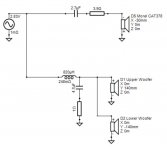
I'm giving my 4 way OB full range dipole design for free under the "do whatever you want with this" licence.

I wrote a bit more about the whole project for the orion pluto lx forum (Linkwitz support group) and done a lot of measurements, this is a copypaste here.

Hi all. My name is Ben. I was born on may 21st, so 521 name (it's date when SL designed the baffle) made me very happy 😀. I've built and enjoyed the lx521 for some years now, and have preached everywhere about how great that speaker is. However, after a long time, I've decided to undertake designing and building a second set of similar yet quite different speakers. There were a couple of goals to achieve:
1st - WAF. Lx521 is very beautiful, especially so if you understand what it represents. But most people think it looks at least weird, if not ugly. I also moved to a smaller space with my wife and needed something more practical and "normal" looking.
2nd - keep all the bass performance, no sacrifices in function to gain WAF and practicality.
3rd - audiophile pals at my place and some at audiophile shows comment how voices sound strange on lx521. I thought about it a bit and, they really don't... but I think I got the gist of the issue. LX521 is a dipole behavior all throughout, meaning it kills room interactions as much as possible, both by radiating 8 pattern (not illuminating sides) and by keeping spectrally very similar reflections to the front wave. But in doing so you disconnect voices from the room and put them in the phantom image alongside the rest of the music. They won't sound like they are actually in the room to some extent - and this can be observed. I didn't really want to admit it because I really like SL and 521, but there we go, it's how it is. In order to get the great soundstage and reflections, you sacrifice a bit of intimacy in vocals. I tried to design a speaker that keeps the dipole behavior through the whole spectrum but expands the vocal range of around 1-4 khz by a bit, by making it radiate somehting between a dipole and omni in that range in hope of adding back that "like in the room" vocals. If that makes any sense. I already have a true lx521 reference anyway.

So after a long time, here is the result of my work. The speaker is called waffle. For the waf. My wife finds them pleasing. It's also possible to add black audio transparent cloth to mask them into black blocks.


wR2srcd.jpg


next to the lx521


BpccPKI.jpg


5GBgRT6.jpg


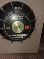
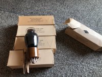
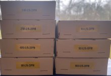
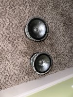
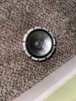
The speakers are made with 16 SB acoustics drivers, from my research really only them and SEAS, mybe scanspeak (expensive) and some vifas made sense. You need very well designed and build drivers with specific traits, like vented spider and so on. The drivers are very nice indeed.


gpdueX1.jpg


U25Cey9.jpg


NtFHp11.jpg


Me next to the speaker, I'm 180cm tall.


cwt0ZL2.jpg


The speaker has full vibration cancelling and 8 bass drivers total. I should point out that I'm not objective, obviously, but the sheer power this speaker commands is ridiculous. Insane amount of highly controlled bass is possible, down to what, 10ish hz or so. It's funny feeling that big articulated power coming from such tiny things, and the inherent complete vibration cancelling is great, absolutelly no vibrations anywhere, together with that monstrously powerful bass. It's weird. The rest is a typical dipole goodness, vast articulated soundstage, but there is a bit more energy in vocals and they do sound like in the room instead of being more ethereal like. It would be relatively simple to undo this with an attachment to the baffle and some more eq, and make it more like the lx521, but where's the point, just get the lx521 then. The 1-4 khz range still behaves like a dipole, just a bit less so, as you can see in the directivity and spectral plots below.
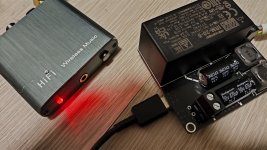
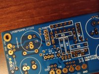
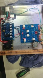
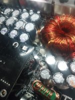
Every single one of 16 drivers in this speaker has it's own amp, so levels of damping and control are really good.
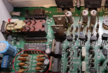
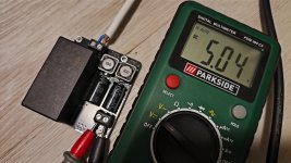
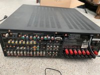
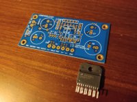
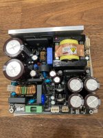
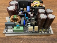
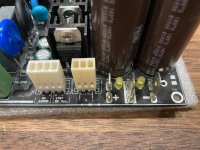
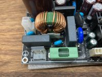
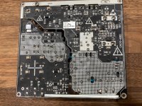
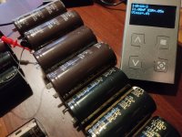
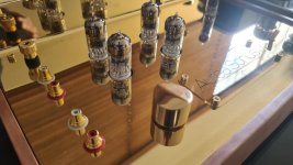
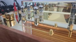
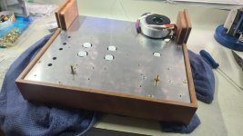
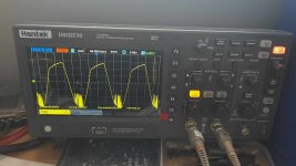
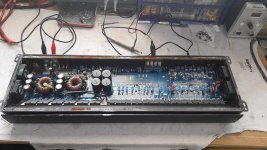
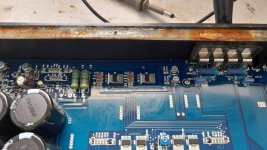
The amp is a 16ch class d amp with 250w per channel. The psu for the amp is literally just 3 atx psu's unearthed and in series to produce 36 volts dirt cheap.
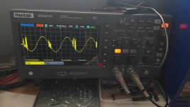

0nCMPQ2.jpg


Some measurements:

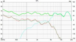
2.88ms gated on axis FR

Twfbtm3.png


1/12 oct smoothed FR

otriGWt.png


bass enclosure response nearfield (front and 2 openings on rear)

gCPywkI.png


Lower midrange response nearfield (front and rear)

JdHYwQP.png


Distortion above 300 Hz, white line is thd (for bass you need something else, which I can measure/plot, but just didn't have the time and it will be good anyway as there really are no issues)

egT2JDL.png


RTA maximum around my room

uxdc7Bf.png


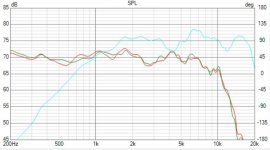
Spectral energy - this 60 hz spike is a room mode. I can see no stored energy above Schroder f, but it is raw so it looks ribbed. For pleasure. There is a bit of "fattening" between 1 and 4 khz, as predicted/wanted, but the on axis FR remains neutral.

hgjiKv1.png


Raw waterfall plot. Again, ignore stuff below 300 Hz.

h6uOaax.png


Nearfield waterfall for low midrange.

WOP531j.png


Nearfield waterfall for subs. There is some stored energy but it's way below anything that would be an enclosure resonance (it should appear at 120 Hz, and it does, you can see it on the far right), and I can hear no problems. I was originaly a bit worried, but now quite sure it's actually room modes because the same pattern apears on the low mid too which has nothing to do with the lower enclosure.

hVRapso.png


Directivity. You can see some really nice dipole behaviour up to 1 khz and above 4 khz. 1-4 khz still exhibits dipole like response but it's much less pronounced, as it radiates some energy to the sides, making vocals more "in room" like but the on axis FR remains flat. As I said, it could be modded to be like a dipole all the way, but you can just have lx521 for that, and it would introduce some other problems too actually.

XM7iqhA.png


I'm no Linkwitz, obviously, but at least I have a hobby.

Attachments

Class aP amplification

The letters aP in Class aP stand for analog Pulse; which characterize operation of this type of amplification. The goals, and proposed merit/value of Class aP will follow as I explain its operation, and undoubtedly from your input.

The generator of analog pulses is the Precision Rectifier [PR] shown in the schematic of the attached image. Here is how it works:
1. The operational amplifier [OA; actual is 1/2 LF353N] inverts sinusoidal input signal Vi.
2. OA has two independent and identical feedback branches emanating from its output and terminating at its inverting input.
3. Each feedback branch has a rectifying diode [actual 1N914].
4. By example of operation, allow the voltage of the shaded part of input signal Vi to increase. It follows that OA creates an inverted version at its output.
5. This step reverse-biases diode D+ of the upper feedback branch, and thus prevents input current [from the sine-wave generator] to flow through it.
6. The instantaneous voltage of the shaded input signal, and the value of input resistor R determine the value of input current moving from the sine-wave generator in the direction of the inverting input of OA.
7. This instantaneous input current [substantial in value] cannot flow in the inverting input of OA because this physical input has a high input resistance. It also cannot flow in the upper feedback branch because D+ was immediately shut off as mentioned in step 5.
8. However, this input current readily flows in the lower feedback branch because OA facilitates it by forward biasing diode D-; by using its important purpose to force zero Vdc or a virtual ground at the inverting input so as to match the actual value of zero Vdc ground of the non-inverting input.
9. Virtual ground is the electrical center point of the shaded parts of the input signal and the shaded output pulse. Both must be out of phase, and have equal;but opposite values for their voltage. This is an informal mechanism used to generate a negative pulse at output B.
10. A similar informal mechanism can be used to generate a positive pulse at output A.
11. This Precision Rectifier cuts the sinusoidal input signal [Vi] into two electrically independent mono polar pulses. Each pulse from this point forward will be processed separately. But both pulses must be processed simultaneously and identically in real time so as to recreate later on the original analog sinusoidal signal as faithfully as possible.
12. The analog pulses at the output A and B begin and end as close to zero Vdc as allowed by OA. This precise dual half wave rectification means that it is repeatable; but one needs to mind its accuracy which has to do with the faithful replication of each pulse regarding its parent portion [shaded and not] in the parent sinusoidal input signal Vi.

The next post will show a concept Class aP amplifier.

Best regards.

Attachments

  • ClassaPfig1.jpg
    ClassaPfig1.jpg
    312.2 KB · Views: 3,228

VAS cascode latch-up

I'm working on a novel amplifier design in LTspice. I'm experimenting with cascoding the VAS transistor, but very often (seems to be kinda random) no current flows thru the VAS transistor and its cascode, or just a few pA. If the current gets started (for example by briefly placing a large voltage on the cascode base) then everything works fine. I have a vague feeling I've read about this somewhere before but can't remember. Is it a real-life issue or just an artifact of SPICE? What's the solution?

BA3 preamp dilemma, add Pearl2 phono stage or make it balanced?

I had a BA3 preamp built to drive an F4 power amp, the case is a huge HIFI2000 one, there already is a dual PSU and enough space to either add the Pearl3 phono stage or a second BA3 and make it balanced.

During a trip to the US I bought extra BA3 cards to eventually either add one to the existing preamp and make it balanced or, in the future, make a simple and smaller footprint one, I also got the Pearl3 kit to build the phono stage, again, either in the same case as the existing BA3 or in a case of its own and then add second board to the existing one and turn it balanced which also means I will have to have the F4 modified to be run balanced.

Only balanced source I use is the DAC, would it make sense to go the balanced route?


Grazie

Giovanni

edit: it's a Pearl 3 phono stage, can't edit the title
Projects by fanatics, for fanatics
Get answers and advice for everyone wanting to learn the art of audio.
Join the Community
507,627
Members
7,880,871
Messages

Filter

Forum Statistics

Threads
405,897
Messages
7,880,871
Members
507,627
Latest member
FHDCrew