Using IGBT modules for low freqency Class D ?

Hi.


I think about a subwoofer Class D design for large car hifi woofer in halfbridge design without an army of countless single mosfets.


There are industry igbt bricks, but they are slow compared to Mosfets.
I think the lower switching frequency cause larger filter output coils.


max output frequency should be around 200HZ.


I think about following IGBT module (Double IGBT H Bridge) IXYS 400-12E4


Datasheet here http://datasheet.octopart.com/MII400-12E4-IXYS-datasheet-8358599.pdf


tdON: 170ns
tr:60ns
Tdoff: 680ns
Tf: 50ns


Could this IGBT be useful for a design like this ?
I read about 10 times higher switching frequency then Output frequency.
Using 100 times more would be 20khz.


Regards

Power Dissipation vs Die Temp Calculator

I came upon this nice calculator which seems very helpful if someone understands how to use it:

Power Dissipation vs Die Temp | Design Center | Analog Devices

unfortunately I don't clearly understand all of the parameters that need to be entered:
VOUT Load voltage? does it mean Vrms??
VGND Load ground? isn't that always "0" ??
RL Load resistance? talking about an amp's output BJTs or FETs do I have to enter speaker's load??

FS: DIY Synergy horn speakers "CoSyne"

These are horns I built several years back. 3-way, 9 driver, co-entrant/coaxial/point source, controlled directivity, linear phase speakers (my own design). There was a build thread at DIYSoundGroup, but apparently it didn't survive the move when they changed their website.
front.jpg
Here are some related threads, though --
DIY Synergy/Unity spreadsheet | HiFiCircuit
http://www.diyaudio.com/forums/multi-way/219870-have-diy-synergy-speakers-doing-almost-linear-phase.html

They are 24"wide, about 48" tall, 12" deep. big but not enormous. But they would be "pick-up only", I don't want to try to pack them for shipping nor deal with crises if they got dropped! Location is in Portland, OR.

Carpentry and finish are "diy" oak veneer (horn is rough-painted mdf), not pro-furniture-craftsman, but I think they would be decent looking in most home decors.

Asking $500 for the pair, a little below the total materials costs, to include several spare drivers of each type.
back.jpg

InsideCaab.jpg

Attachments

  • boxes.jpg
    boxes.jpg
    23.5 KB · Views: 1,251

Building a Chinese clone of ARC LS 10ish

Hi guys, I am an audio enthusiast, retired and therefore on a tightish budget. I like to keep my mind active and building kits etc is the way I do it.
I have already purchased this kit : Hi End AudioResearch ARC Tube Preamplifier XLR Balanced Or RCA Input&Output,12AU7/ECC83+ECC88/6DJ8 Preamp DIY Kit-in Amplifier from Consumer Electronics on AliExpress and was just wondering if anyone else has built one and what the sound quality was like.
I have purchased a Hammond transformer to power the pre.
Thanks in advance,
Gordon

Technics Class A Bias Circuits

Hi, Been doing some research on Class A bias techniques and
ran across Technics Class A Synchronous bias and their
balanced bridge network using two amps {Voltage class A)and
(Current Drive). I would like to know how effective these
aproaches were in attaining Class A operation,(Sound Quality)etc,etc. I think some of these models were SU-V7,8,
SE-A100 etc,etc.
Also I see where Nelson Pass had some good ideas and patents
on the subject.

Thanks
SDMAN

Newbie Question on tweaking Mission M71

I am new to DIY and am thinking of tweaking my Mission M71 bookshelf speaker. The speaker sounds quite harsh. I got it second hand and some ppl are suggesting that I should recap it. I'm new to all these so I'm here to ask for opinions from you gurus here. Please let me know what should be changed. Thanks for any help. Here are the details about the speaker:


Crossover
-------------
L1: ELYTONE 2000L.39
C1, C3 : ELYTONE 10uF +- 10% 63V NP
C2 : 5.0K 100V
R1, R2: 5W 2.2 Ohm JF


Enclosure type: 2way reflex loaded
Freq Response: +-3db 65Hz to 20kHz
Crossover Freq: 2.8Khz
Nominal impedance: 8 Ohm compatible
Recommended Amp: 25-75 W/ch

An externally hosted image should be here but it was not working when we last tested it.


An externally hosted image should be here but it was not working when we last tested it.

New Laptech 45M/59M pair HC43 SC cut

Brand new pair never out of the bag.
$100 shipping included to NA.

SC-cut, 3rd O/T
Package: HC43 Cold weld.
Calibration @ LTTP 82.5C: ±3ppm
LTTP:75C to 90C
Load capacitance: 16.5pF
Shunt capacitance C0: 4.0 pF
C1: 0.15fF
Drive level: 100uW

Here are the detail parameters,
XT4338
45.1584M
LTTP 84C
ESR 35ohms
C0 3.4pf
C1 0.4ff
Q 250K

XT4339
49.1520M
LTTP 85C
ESR 36 ohms
C0 3.4pf
C1 0.4FF
Q 230K

Attachments

  • laptech.jpg
    laptech.jpg
    133.2 KB · Views: 254

servicing intervals

Hi all,

I serviced my el84 amp over the weekend. It wasnt pretty, 1 cap on the verge of failure, 3 bulging but may have been fine for another year or so, and 1 suspect (but meaured fine, just looked a bit cooked) resistor. Its a baby huey type circuit, the balance of anode voltages on the signal tubes was also now way out.

Thats a 10 year old amp.

Out of pure interest, whats the typcial servicing intervals you stick to? what do the commerical producers recommend?

cheers

FS: Denon DL160 with broken cantilever

Just what the title says. Low hour DL160 with a broken cantilever. It sheared right off at the entry to the cartridge. The remainder of the cartridge appears perfect. Had I left the stylus guard down this probably wouldn't have happened, but...(hey, it could have been worse, it could be an encrypted hard drive with $220 million in bitcoin on it)

I have the original box and paperwork, but there are some bits of plastic from the internal plastic box that are missing. The external cardboard box is mint if that's important to you.

I am accepting offers. Please offer whatever you think it is worth. I will accept the best offer by Friday (Feb. 5). Shipping is paid by the buyer at cost. I am in the Boston area.

Again, to be clear, this cartridge must be repaired and does not work as is.

Vacuum tubes, Mil Spec old stock.

Vacuum tubes, Mil Spec old stock for sale.

Tubes for sale.

Please see attached word-file.
Military tubes from Swedish Air-force are tested and sealed, some of them 1945.
I have opened some of them to check.
There are also some singles of very old tubes. The tech that saved them were a meticulous man, so I assume they are OK.

I have no equipment to test them.

Prices are for the indicated quantity of respective type. I rather not split posts, except for those with more than 4 pcs.

Shipping excluded.

Please PM me if interested.


Best regards.

Figge

Attachments

  • 20201220_153206.jpg
    20201220_153206.jpg
    268.8 KB · Views: 434
  • 20201220_155010.jpg
    20201220_155010.jpg
    202.1 KB · Views: 428
  • 20201220_194244.jpg
    20201220_194244.jpg
    188.5 KB · Views: 435
  • 20210109_191348.jpg
    20210109_191348.jpg
    221.1 KB · Views: 429
  • 20210109_191638.jpg
    20210109_191638.jpg
    270.8 KB · Views: 424
  • Tubes1 - kopia.doc
    Tubes1 - kopia.doc
    51.5 KB · Views: 213

Replacement for 20k AX2 volume pot in Arcam Alpha 3

Hello all, I got my old Alpha 3 out of the loft in preparation for a house move and I notice a lot of noise on the volume pot. Obviously I could dismantle it and clean it out, but I thought a replacement and upgrade would be better. I've had a look online at ALPS pots and can't see a direct replacement, in particular they have flat sided shafts rather than knurled. The shaft looks to be 18mm long.

Pasteboard - Uploaded Image

Pasteboard - Uploaded Image

An externally hosted image should be here but it was not working when we last tested it.


An externally hosted image should be here but it was not working when we last tested it.


Can anyone recommend a replacement? I've seen something that looks the same as the one fitted, 20k Linear Stereo Potentiometer | Switch Electronics but I think my Alpha deserves something that costs more than 60p.

Many thanks.

Functional relationship between woofer Rms and Cms

Greetings to all!

I have been trying to understand the functional relationship between woofer Rms and Cms. Other T/S parameters don't seem confusing, but these two and their effect on Qms seem to be a bit counter-intuitive, and at times even inconsistent in observations made over data of a few drivers.

My questions as of now remain:

1. Do i understand this correctly that Rms and Cms are necessarily inversely related to each other?

2. In the formula for Qms, i noticed both Rms and Cms being used as components in the denominator. Could it be reliable? My understanding of algebra is very poor, so I could have quite misunderstood it all! 🙂

So how do Rms and Cms each affect Qms?

3. What type of sonic behaviour can I expect from a driver with each of these variables I.e. Rms, Cms and Qms being lower or higher?

4. I have read conflicting statements. Some say EBP is important; whereas some say Qts is all that affects bass alignment, regardless of individual components (Qes and Qms). How can these two conflicting statements be reconciled?

5. Given that I have no means to measure parameters, and driver data doesn't mention Rms and Cms values, is it wise to rely solely on Qes, Qms, Qts & Vas?

I have been looking for clear insights in this regard, and have turned to this very useful forum as the last resort. Could any of you please help me by directing some light on this?

Thanks to all of you in advance!

Warmly,
sujat

Virtual ground (3-channel) amp

The pix shown are from a pocket LM-6171-based 3-channel headamp from an old (2006??) project. (the photo with two amps shows another similar-sized project, but is not 3-channel).
Virtual ground headamps were quite popular about 12-13 years ago, esp. on head-fi diy forums.
Note that non-use of dual-voltage (e.g. two 9v batts) was not the main criteria.
Yes, NWAVguy did write that lengthy article. Which is interesting but quite verbose.

IMG-0248.jpg


image.jpg

CDM9 / MM T-Drive faulty?

Hi All,

did quick search across the threads, but nothing helpful so far.

Got T-Drive (MK1) older revision with CDM9/65 which can not read TOC from CD. After loading it spinning the disc OK and then start reading the TOC but without any result - it goes endless process without any outcome either erroneous or successful. LD is faulty hands down? Or it is possible to go for some checks before I throw a hundred bucks at ebay replacement.

I did figure that laser assembly goes for standard route after loading - its trying to focus and beaming

video is here: CDM-9 of Micromega T-Drive - YouTube

I can also see there's no pot adjusting LD current... Thoughts?

RIAA Pickering 132E

Здравствуйте.Помогите найти информацию о корректоре Pickering 132E,как правильно подключить и схему?Спасибо всем, кто поможет

:cop: this is an English language forum. Please use English in the future. Thank you for understanding :cop:

Hello. Help me find information about the Pickering 132E corrector, how to connect and the circuit correctly? Thanks to everyone who will help

Replacements for 2SA 1295 PNP, & 2SC 3264 NPN

Hello All,
I am looking for replacement/alternatives to BJT's : 2SA 1295 PNP; & 2SC 3264 NPN,
These are needed for a 120Watt/8R power amplifier and were originally recommended by Mr D. Self in one of his power amplifier designs. However, those particular types are no longer in production and there seems to be no direct equivalents.
If anyone can point me at suitable, currently available alternatives, I would be most grateful.
I can make a selection from the data sheets, hopefully a good choice, but the experience of those who have gone before is always invaluable ....
Many thanks in advance, I look forward to your advice,


Best regards,

Two JBL 1500AL Subwoofers for sale

One Pair of JBL 1500AL drive units (as new and boxed) These are the 15" Alnico magnet drivers found only in the flagship 9800K2. Available only in Japan at retail, where they cost £1,000 each.

I also have two 115 litre vented cabinets that were built to specs from Greg Timbers using 1" MDF, 1.5" Front baffle and substantial bracing.

The subs just need someone to play around with the internal damping should they so desire. As they stand they sound excellent. The port tuning frequency is 27hz.

As I understand it, harman do not offer these units for sale in most of the world. I am open to sensible offers for what is a very special project.


Thanks for looking

Michael

Sonic Frontiers Power 3 Help Needed

Hi all,

I have a friend who owns a pair of Sonic Frontiers Power 3 amps. Unfortunatly, one of the power supply transformer has blown up.
He succeed to find someone who's able to rebuilt one but he would needs the schematic.

Does someone have them and could give them to me? I would really appreciate and my friend will also i guess.

Many thanks in advance for the help you could provide.

First Crossover Design Advice

I am planning on building my first own Speaker which should be a 2-way.

I designed this Crossover in VituixCAD and am pretty happy with the curve, just wanted to have experts have a look on it and if there are any major problems or things I have overseen because designing this seemed relatively easy 😕

Screenshot by Lightshot

Drivers are the Dayton DSA175-8 and the Dayton DC28F-8

Designing a universal diff-in/diff-out Head Amp

There are quite a number of circuit diagrams for (differential) Head Amps available;
point is that most of them are either very complex, consuming large amounts of energy, or to be assembled from a large number of selected Fets as input devices.
To make a difference, I used the following points:

Diff in
Diff out or SE out
No caps in the signal path
To be either supplied by a 5V power bank or a USB mains supply.
As simple, yet as powerful as possible.
Selectable as a voltage or as a current input circuit.
Wide range of selectable Gain settings


Latest Update

I noticed that the dropbox link with all circuit diagrams, pictures, Boms and Gerber files was no longer active,
that's why I reinserted it here:
Dropbox - Zip Files - Simplify your life

And here is a link with all the specifications:
Dropbox - This universal Diff In.pdf - Simplify your life


Hans
  • Thank You
Reactions: Drbulj

Help with replacement parts for B&K

My old but trusty B&K av5000 series ii finally let me down. One of the channels started distorting really badly. Tracing the circuit back led me to a blown Q12 2n3440. Everything else seems to test fine.

Should I be trying to find original Motorola transisters or will newer replacements from Central Semiconductor work just as well?
https://www.mouser.ca/ProductDetail/Central-Semiconductor/2N3440-PBFREE/?qs=u16ybLDytRbmQdZPnRs14A%3D%3D

Assuming if if Q12 is replaced its a good idea to also replace Q4?

Likely recap while its apart. Looking at the schematic is there anything else to inspect or replace?

Thanks!

Attachments

SigmaLink USBi driver issues

Solved!
I finally managed to get my SigmaLink USBi programmer for SigmaStudio. But after plugging it in to my windows 10 PC all i get is a message box with the message "Unknown USB Device (Device Descriptor Request Failed)".

I have tried to follow the driver install manual from freeUSB, but that doesnt seem to get me anywhere, since windows does not seem to be willing to install or use their drivers either for my USBi programmer.

Does anyone have any advice? the USB cabel is brand new, and i have the same issue on both my personal and work pc.

Edit:
Everything works fine after installing Zadig. Dont know what it was but now it works.

OPA1622 Question

Hi,


According to the datasheet, the OPA1622 can connect to the outside world without a build-out resistor or series cap, and it has internal short-circuit protection. I've never used any form of opamp in my life without some form of output R or C, and it makes me feel a little nervous doing so.

Does anyone here have experience with using the OPA1622 in this way? Is it really that rugged? And is the DC offset that low (assuming correct implementation)?

Thanks in advance.

Where can I source the Little Dot I+ enclosure?

I have a Little Dot I+ that has lost the bottom of the case! I have searched on eBay and some of the parts shops and only found cases that are not the same size. Is it possible to buy another case somewhere on the internet that is the same as this so I can replace the bottom?
An externally hosted image should be here but it was not working when we last tested it.

An externally hosted image should be here but it was not working when we last tested it.

This case is approximately 154mm x 92mm x 40mm
Your help is greatly appreciated.

  • Locked
Got the vaccine yesterday

Yesterday was the first day that my health care provider started offering the covid vaccine (Pfizer) to 65-74 year-olds, and I was notified late in the day, but in time to drive over and get the shot.

Side effects have been mild (a little nausea, even less headache, but damn sore shoulder) and nothing that a martini couldn't help with. (But not two, that would be wrong.) The shingles vaccine that I got in 2019 was much worse.

Still amazed that they were able to produce an effective vaccine is such a short period of time, and I'm hoping that it can be manufactured and delivered to all that need it in a reasonable time frame.

Stay healthy, my friends.

Open Source "Tower XL"

Important note Nov. 2018:
This free open source project is for DIYers only. DIYers may build and enjoy and maybe adapt this project for their own personal use, This project made possible by a lot of members donating their time, experience and money. Please do not use the information developed in this open source project in ANY commercial use or product.


Following "Open source speaker project?" and "Open source speaker project - Part II" this thread will be design thread for "Tower XL".

Tower XL Goals : amp friendly (high efficiency) and flattish impedance curve of 8 ohms, low bass extension of 35-40Hz within -3db and cabinet volume will be up to 150 liter. Drivers costs will be maximum of 1000$ for the pair ( excluding crossover parts and cabinet).

Drivers will be chosen to meet the task's goals (no size criteria at this point). Stated goals are not fixed and may change (not drastically) as design team needed.

and of course everyone is welcome to help and participate 🙂

Update (10-22-18):

It will two versions of Tower XL, Acoustic Elegance and Faital Pro Versions.

After a lot discussions, research and simulation Acoustic Elegance TD15X has been chosen as the woofer for this project, but due to limited worldwide availability and high shipping costs and manufacturer lead time, we decided to go with two versions and Faital Pro 15H520 as the woofer of choice for alternative version with trying to keep same form factor in mind, front baffle will be the same dimension for both versions but due to higher VAS of AE driver the AE tower need will be deeper.
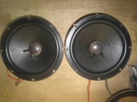
Midrange: AE TD8M will be used for AE version and for Faital Pro version current candidate is Faital Pro 8PR200.
Tweeter: Faital HF107 + STH100 is the driver of choice for AE version.

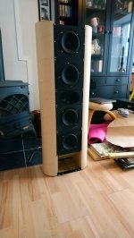
More details about cabinets:

Tower XL AE
- Cabinet W x H x D = 47 x 112 x 62 cm
- Woofer AE TD 15X, Midrange AE TD 8M, Tweeter tbd
- 247 L bruto and 217 L netto for the woofer; 20 L bruto for the midrange, 5 L for the woofer and 5 L for the bracing subtracted
- Internal cabinet netto volume for midrange is 15 L
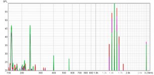
- Port length long: FB = 20 Hz, F3 = 35 Hz, F6 = 24 Hz, F10 = 19 Hz
- Port length short: FB = 28 Hz, F3 = 28 Hz, F6 = 25 Hz, F10 = 22 Hz
- Data for BR simulation: netto volume = 43.2 cm x 57.1 cm x 88 cm or 217 L; port long = 57.9 cm; port short = 24.0 cm; port area = 236 cm2

Tower XL Faital
- Cabinet W x H x D = 47 x 112 x 50 cm
- Woofer Faital 15FH520, Midrange 8 inch tbd, Tweeter tbd
- 195 L bruto and 165 L netto for the woofer; 20 L bruto for the midrange, 5 L for the woofer and 5 L for the bracing subtracted
- Internal cabinet netto volume for midrange is 15 L
- Port length long: FB = 25 Hz, F3 = 53 Hz, F6 = 34 Hz, F10 = 22 Hz
- Port length medium: FB = 36 Hz, F3 = 35 Hz, F6 = 31 Hz, F10 = 28 Hz
- Port length short: FB = 39 Hz, F3 = 36 Hz, F6 = 33 Hz, F10 = 30 Hz
- Data for BR simulation: netto volume = 43.2 cm x 45.1 cm x 84.7 cm or 165 L; port long = 57.9 cm; port medium = 24 cm; port short = 13 cm; port area = 236 cm2

more info can be found here.

Soundstream picasso p1.1500d power supply issue

Hi guys,

Got a Soundstream Picasso P1.1500d, but is has a defect in (I quess the power supply) which I could not fins.

The amp had burned power supply fets on one at least one transformer.
There were 2 faulthy output fets as well, so I quess thats where the main problem was in first case.

I took out all the fets, included the rectifiers. Put some better IRF3205's in, but the power supply (I suspect) is making a pretty loud ticking sound (frequency of the ticking becomes higher when I apply more current).
The PWM drive to the gates are ok without PS fets in.

Wiggling on the transformer winding does not help, and it actually reads OK (comparing both transformers, they have 8% tolerance with eachother)

Anybody has an idea?

Attachments

  • 16116757532765448236091008868180.jpg
    16116757532765448236091008868180.jpg
    1,010.9 KB · Views: 102
  • 16116757758183320990077249595159.jpg
    16116757758183320990077249595159.jpg
    639.3 KB · Views: 95

NAD 3130 rebuilding

Hi I am rebuilding the NAD 3130 integrated amplifier.
I replaced two pairs power transistors 2N3055 and MJ2955. As soon as I put the screws, the transistors are shorted to ground. the collector closes to the radiator. All insulation is ok, screws are all well insulated. if I do not put the screws, there is no closure. What to check? Thank you.

SM
NAD 3130 SERVICE MANUAL Pdf Download | ManualsLib

ICEpower 200ASC inside speaker enclosure

Thinking of making a pair of active speakers with these modules, and I have a couple of questions I was hoping someone could clear up:

- Would it be OK to place them inside the enclosure with regards to heat?
- Some of the mounting points on the boards are meant to go to ground (e.g an aluminium enclosure etc), while I was thinking of mounting them directly to MDF or a plastic board. Is this a problem?

Quad esl 57 hard match

Hi everyone, I bought this pair completely refurbished of esl 57 they played great one week and then the nightmare begun...one still perfect, dead silent when powered on without music, but the other one click, pops, frrr coming from a bass panel so I decided to replace that panel, shipping back and forth and then installed new panel worked good one day, and then here we go, same click, pop and frrr from the same place even the panel is new, and now just to complete the situation a frrr came up on some bass frequency on the oher bass panel, same speaker. Please help. Many Thanks.

Another Use for 6AV5GAs; Pass Tubes in Regulated Power Supply for SE Amps

From FleaBay I bought a mediocre Heathkit PS-3 Power Supply, the predecessor to the much better PS-4 and IP-32. Turns out is wasn't quite up to "mediocre"; the seller didn't remove the tubes, and both 1619s fell out and got their guide pins busted. Plus, the original builder apparently used 1/4" solder and a heavy hand, so every solder joint had big globs of solder (poor kit builders are always a risk with Heathkits, of course).

Never liked the PS-3 design anyway (the pass-tubes are 1619, which are directly heated beam tetrodes with 2.5V/2A (!) filaments; Heathkit likely got a huge stock from WWII surplus), so I decided to rebuild it as an SE or small PP prototype Power Supply using my favorite Black Sheep tube, the Sylvania 6AV5GA.

Kit power supplies of the era (the later Heathkits, plus the EICO 1050, for example) often used 6L6s as pass-tubes, usually the GCs in later models, but I figured somebody had to have used the 6AV5GA, probably triode strapped. as it was (and is) a lot cheaper than the 6L6GC (audio) tube, and was close to ideal as a pass-tube when triode strapped.

Indeed BOTH General Radio AND HP used either the 6AV5GA or its cousin the 6AU5GT as pass tubes. The best implementation was the P/S in the HP 202A Function Generator, which used a 5U4GB + CLC filter, which I preferred.
Tubes were 2 x 6AV5GAs + 6AU6 error amp + 0A2 cold diode ~150V voltage reference tube. I have several dozen 6AU6s, and two 0A2s came with the PS-3, and I have half a dozen well-seasoned 6AV5GAs.

I removed the old 6SJ7 octal error amp and the 6X5 bias rectifier, which left enough room for a Triad CX-14 choke. Reworked the reference voltage divider in the HP circuit, including a 100K 10 turn pot, so the circuit would be centered on 300 volts, and adjustable from about 250-350VDC output, depending on current. Otherwise it's the stock HP circuit, except of course that the Heathkit transformer is 380-0-380 instead of the 475-0-475 HP PST.

I stayed with the 0A2 tube voltage reference because (a) it's a TUBE (duh) and (b) it makes a nice purple glow (see (a)). A zener would likely be more consistent but subject to thermal drift; cold cathode tubes apparently can have slightly different values each time they are started-up, but don't drfit as much with temperature. Besides, Zeners need to be decorated (ie bypassed) with a couple of caps to eliminate the avalanche noise; well, I guess unless you use a string of 6.3 volt ones. Purple Glow Tube it is.

I set the pot exactly mid-span and powered it up with a 2K ohm load; after about 10 seconds, the meter needle swung-up to 300 VDC, spot-on, and stuck there. Current was spot on at 150ma.

Subsequently I've been heating the shop with my little resistor bank at 310V and 160mA just to see how the 6AV5s like the continuous high current. No embarrassing redness after the first hour. This isn't surprising, since I've run Sylvania 6AV5GAs (including these exact tubes) at 80 mA in a Simple SE without problems.

Unfortunately, the PST is barely warm pushing 160mA, so I am obviously a woosie. I need to scrounge-up some more load resistors.

See the photos below.
I completely disassembled the badly-built PS-3, salvaged the sockets and the needed power resistors, cleaned-up the chassis, and rewired. All told, took about ten hours. Only new significant part was a $12 Bourne 10-turn 100K pot (the blue thing on the panel); one turn equals about 10VDC (a little too fine) so I might adjust the voltage divider resistors to make the adjustment more coarse.

The power supply schematic is in the HP 202A manual at www.hparchive.com/Manuals/HP-202A-Manual-SNprefix-037.pdf if anybody is interested.

I figure I'll add a S/S bias voltage supply for fun; S/S seems to be a really good idea for a bias supply; bias turn-on is practically instant, so there's a bias voltage on your grids long before the B+ hits the plates.

Attachments

  • PS-3 Chassis.JPG
    PS-3 Chassis.JPG
    576.2 KB · Views: 434
  • PS-3 front panel.JPG
    PS-3 front panel.JPG
    470.1 KB · Views: 423

Measurements of LJM CS4398 USB DAC With NJM4580D

In case it helps someone else in a purchasing decision I have enclosed measurements of the LJM CS4398 USB DAC with my choice of NJM4580D op amp installed.

The distortion is pretty much at the limit of my SB0490 to measure. It is still worth measuring because it could help detect a major layout or power supply issue.

I do see a strong roll off at 20 kHz and some ripple. Can anyone comment on that? Expected? Anyone else measure the same? The filter is stock except for the NJM4580D.

I use it with my project amplifiers with the volume potentiometer at maximum and using software control of volume. I think that sounds better than setting the DAC at maximum/full scale and then controlling the amplifier with the potentiometer.


If anyone knows how to get the EMU 1820m working with Windows 10 then I could remeasure with a better ADC.


I would appreciate any advice/help/comments on improving the measurements. One of my hobby goals for 2021 is to add good quantitative measurements to my experiments. (Especially evaluation of my project amplifiers.) Next I am going to try to figure out how to measure the CIRMECH CS4398 (did not measure properly with the SPDIF output of the SB0490) and then one of my project power amplifiers.

Attachments

  • LJM CS4398 DAC NJM4580D Measurement Setup.jpg
    LJM CS4398 DAC NJM4580D Measurement Setup.jpg
    993.3 KB · Views: 402
  • LJM CS4398 DAC NJM4580D 220uF Panasonic M.jpg
    LJM CS4398 DAC NJM4580D 220uF Panasonic M.jpg
    1,003.4 KB · Views: 410
  • LJM CS4398 USB DAC NJM4580D Measured By SB0490 10Hz.png
    LJM CS4398 USB DAC NJM4580D Measured By SB0490 10Hz.png
    142.1 KB · Views: 345
  • LJM CS4398 USB DAC NJM4580D Measured By SB0490 1kHz.png
    LJM CS4398 USB DAC NJM4580D Measured By SB0490 1kHz.png
    126.3 KB · Views: 336
  • LJM CS4398 USB DAC NJM4580D Measured By SB0490 10kHz.png
    LJM CS4398 USB DAC NJM4580D Measured By SB0490 10kHz.png
    121.2 KB · Views: 290
  • LJM CS4398 USB DAC NJM4580D Measured By SB0490 20kHz.png
    LJM CS4398 USB DAC NJM4580D Measured By SB0490 20kHz.png
    125.3 KB · Views: 226
  • LJM CS4398 DAC NJM4580D 10uF Ceramic 100uF Electrolytic Bypasses.jpg
    LJM CS4398 DAC NJM4580D 10uF Ceramic 100uF Electrolytic Bypasses.jpg
    781.3 KB · Views: 271

Bluetooth Aptx with toslink output?

I'm looking for the best and cleanest source for spotify and Flac files for my car.

Right now I'm using my Oneplus 6t through bluetooth to my pioneer head unit and then RCAs to a Helix P-DSP, than RCAs to my amps.

I just noticed the DSP has a digital optical/toslink input.
The DSP has Burr Brown Dacs and Adcs, so rather good sound quality.
(And the same Dacs I have in my home setup)

Then I thought, what about using a Bluetooth 5.0 AptX HD receiver with a toslink output?
My OP 6t has AptX HD support and I can buy a Volume control for my DSP.

Would that not be the ultimate signal in my car for both quality and convenience?

If I remember AptX HD maxes out at 24bit/48KHz, which is plenty because most of my music is still 44.1 or 48Khz.

My biggest problems are, I would want the bluetooth to reach like at least 5-10m outside of my car and where do I take the 5V power.
I was thinking about the USB output behind my head unit or worst case scenario is a car charger.


Would you guys have recommendations for a receiver to buy in Europe?
The less expensive, the better. I don't need a battery. And I would like it to turn on with power and auto-connect and not to turn off.

Buffered Preamp or Passive Volume Control?

I'm planning on building a new line preamp with a stepped volume control connected to a buffer, either the Pass B1 Buffer or a pair of ICs connected in voltage follower mode as I want no gain. However, after reviewing the specs of my system I'm wondering if a passive volume control might be an option enabling me to omit electronic circuitry altogether. I would appreciate any advice on this matter as I'm willing to go either way depending on the viewpoints advanced here. I realize the ultimate test would be to listen to both versions, but short of that, I'd be interested in your opinions.

My system consists of a Marantz CD player and an Audiolab AM/FM tuner connected through my present preamp to a Bryston 3B power amp. My present preamp is on the way out necessitating my need to replace it.

The output level of the CD player is 2V RMS and the output impedance is 200 ohms. It is connected to the preamp with a pair of 18" long interconnects.

The output level of the tuner is 700 mV RMS and the output impedance is 100 ohms. Interconnects to the preamp are also 18" long.

My power amp has an input sensitivity of 1V RMS for full output and an input impedance of 50K ohms. It is connected to the preamp with 3' long interconnects.

With a passive setup, I'm planning on using a 10K stepped attenuator. My reasoning is that this impedance is more than adequate for both sources but I'm not too sure how it would match up with my power amp's input impedance of 50K ohms. However, at least the output levels of the sources seem to indicate that voltage gain would not be required to reach full power output. As I said, any thoughts about this would be greatly appreciated. Should I end up going with buffered outputs I would probably use a 50K stepped attenuator.

Altec VOT in a new position

Hello,
When i bought my property some decades ago i brought my Altecs VOT and put them close to the corners of the room. Pointing the TAD2001 horns on top slightly to the center of the room to reduce reflections from the arcade like wall. When i moved in i tried breaking it down but i soon came across some reinforcing rods so probably it was more than a nice element with sliding doors to create a bit of separation. Neighbouring houses did change the shape of the arcade but in all 7 identical houses non of them is removed.
Removing the biggest part of the arcade would require an architect to do some calculations.
Because i changed the wallpaper in the major part of the room into cork tiles i asked myself why not change the position of the VOT. After all no matter where you put them nearly every new visitors first question is about my speakers especially non-audiophiles.
So in this position both VOT have a so called wing on the outside. Because the electronics connected to them need some work they are not playing yet. Pano, one of the experts here, told me to expect a deeper soundstage. Front of the speaker distance to the back '' wall '' is about 3 meters. There will be less reflected sound.
The distance in between the cork cabinets is about 1 meter so 3 feet. The TAD can be angled a little more in a straight line to widen the soundstage i presume.
At first my idea was to add wings on the inner side of the VOT too. Didnt want to drill holes in the cabinets so i thought about mounting two panels between the wooden bar in the arcade and the floor like a pair of saloon doors. I still have a few square meters of cork tiles like the ones on the wall.
BUT this kind of construction would maybe create to much of a room divided into two parts. Behind the speakers are my records and books so i will have to be there sometimes. This is also the sunny side of my house so i wanna enjoy the free light and warmth.
Because i just ordered about 65 meters of 30 mm diameter bamboo to create a kind of privacy curtain, artwork and diffusor in front of a balcony door the thought about using bamboo between the two VOTS popped up.
In front of the door i will hang two strings composed of one foot long bamboo shoots in a zigzag pattern. Because of the round structure and the zigzag i expect a kind of diffusion anyway better than a door mainly composed of glass.
NOW between the cabinets there are several thoughts, issues, questions.
I dont need to create privacy here so i can let the individual strings touch each other.
I could create a more open structure in the area situated above the cork cabinet by using not 30 but 15 mm diameter.
Wont the creation of a bamboo curtain in between the cabinets affect the depth of image? Then 30 mm in between the cork and 15 mm from where the TAD starts would be nice.
30 mm bamboo would create a nice '' up and down '' shape. Could even use bigger diameters but visually to big diameter will not look nice because the area between the cabinets is not big.
Would a closed curtain with all the bamboo strings touching each other be an advantage to make it function as a wing?
Maybe the wing should have a more solid structure like a wooden panel would have. Bamboo has nice acoustical properties they say but it is very light. Being hollow i could fill the parts with sand.
Any idea is welcome.
Greetings, Eduard

Eton SDA100.4 problem

Hi guys,

Started again on my amplifier which I already struggle on for a while. I have not worked on this type of class D before.

This amplifier actually has no signs of damage.
The power supply works excellent. The amplifier goes into protect (red light) and then after a second it burps into blue light, almost directly it goes into protect again. This is a constant repeating loop.

Output fets have already been removed once, but it still goes into protect.

Does anyone have a idea?

The power supply always works

The output section seems to not send a PWM wave to the output fets (also with output fets removed it goes into protect)

Attachments

  • 16116767238135397076174639634123.jpg
    16116767238135397076174639634123.jpg
    1 MB · Views: 131
  • 16116767584975742820227720201100.jpg
    16116767584975742820227720201100.jpg
    901.5 KB · Views: 114
  • 16116767908626760317082248389715.jpg
    16116767908626760317082248389715.jpg
    983.1 KB · Views: 104
  • 16116768273284959230492097006871.jpg
    16116768273284959230492097006871.jpg
    712.2 KB · Views: 105

3 way monitors - thoughts

After watching a fair few videos and not doing enough technical reading I have come up with an idea for a 3 way monitor design, sorta based on a series that finished abruptly at stage 3 of 5 on the Kirby meets audio youtube channel.

Driver selection (based somewhat on what's available in Australia and cost with an simple requirement to keep them all the same make).

Dayton:
RS225P-8A Woofer Dayton Audio - RS225P-8A 8" Reference Paper Woofer 8 Ohm
RS100P-8 Mid woofer Dayton Audio - RS100P-8 4" Reference Paper Midwoofer 8 Ohm
ND25FA-4 Tweeter https://www.daytonaudio.com/product/1196/nd25fa-4-1-soft-dome-neodymium-tweeter-4-ohm

Crossover design using xsim (vituixcad has too steep a learning curve)


An overall cabinet size of 33.1cm x 42cm x 25.4cm (24.15litres)

I'll be making a pair.

I actually think I'm overcomplicating this as a three way and could get rid of the woofer and put in a bigger mid woofer (or two) and a simpler two way system, but what do I know?

Any constructive inputs would be appreciated

Thanks.

Attachments

  • 3way.jpg
    3way.jpg
    20.1 KB · Views: 382
  • 3wayFR.jpg
    3wayFR.jpg
    64.3 KB · Views: 353

Testing 2-way vs 2.5-way vs 3-way IMD

Hi!

I'm trying to find the differences in distortion between 2-way, 2.5-way and 3-way configuration for my new WMTMW or MTM project.

I thought some of you might find the results interesting as well, so here it is. I'm measuring at 0.5m distance. All 3 configurations are equalized to match in frequence response and level and i am using a single woofer for the 2-way test and two woofers for the 2.5 and 3-way.

80hz and 1500hz sine wave is played simultaneously.

Green is 3-way LR24@400hz.
Purple is 2.5way with a 1.order lowpass at 300Hz.
Red is one woofer fullrange with BSC.

overview:
attachment.php


zoomed in:
attachment.php


speaker: (only upper two woofers in use)
attachment.php


Any thoughts? Doppler distortion is very apparent in both 2.5 an 2-way. Is this an audible phenomenon?

Attachments

  • imd_test.jpg
    imd_test.jpg
    113.4 KB · Views: 1,575
  • imd_test_zoom.jpg
    imd_test_zoom.jpg
    108.7 KB · Views: 1,586
  • DSC_0417.JPG
    DSC_0417.JPG
    74.2 KB · Views: 1,486

Noob Greetings from Maryland.

Hi.

Greetings from Maryland. Glen Echo, MD to be exact. Just outside of DC. Today I ordered an Elekit TU-8600s. I'm very jazzed to build my first amp and then enjoy those 300Bs. Here's what I've got:

-- Running Spotify 320kbps, and I'll audition Tidal FLAC soon.
-- Old Sonos Connect
-- Soon to be built TU-8600s (Lundahl) with Cossor Black 300Bs.
-- Vintage Klipsch Cornwall Is in the room corners.
-- My listening room is our living room in a converted church = big room 8,000 cubic feet of air
-- Thinking about: 1) possibly bi-amping with a SS on the woofer. 2) miniDSP 2x4 HD for room correction/active crossover/DAC. 3) No miniDSP, and use a DAC instead. 4) No miniDSP or DAC.
-- And how could I not start to think about building my own speakers??

Aaron

Anyone built speakers using real wood?

I'm building a small 2 way using a seas 5.5" midbass, and saw sheets of Vietnamese rubber wood, being sold as a kitchen timber bench top, 25mm thick that looked as though it would make a nice cabinet material. I know that real wood isn't used often, but I'm really tempted to use it. I will still properly brace and damp the midbass enclosure, and the speaker is definitely in the mini monitor category.
Rubber wood is a composite hardwood made from felled rubber trees and, I think, kiln dried. If anyone has built a speaker from real hardwood how did it work out, and would you do it again?

Chinese tubes? What to think?

I was just asked by an online audio buddy, if any of the Chinese tube amps on Aliexpress and such sites are any good, or if all of them are trash awaiting victims, lol?
I have NO clue, so thought I'd ask here. He wants to buy a reasonably powerful tube amp, and has sent me photos of some amazing looking stuff! But does any of them have sound to match? I'm guessing they probably are all the same.

Electronic Design Magazines from 66 Bill Z Johnson

Would anyone be interested in a couple boxes of Electronic Design Magazine from 1966 that were once owned by Bill Johnson of Audio Research Fame??

Just hate to toss these.

Payfor shipping and a Big Mac. or trade for some thing cool/interesting


Zc

Attachments

  • 20210202_190947.jpg
    20210202_190947.jpg
    663.8 KB · Views: 92
  • 20210202_190959.jpg
    20210202_190959.jpg
    590.2 KB · Views: 91
  • 20210202_190951.jpg
    20210202_190951.jpg
    1.1 MB · Views: 96

Lectron JH50 Tube Bias

Hi, gang. This is my first visit to this site, so please be gentle. I have long had a Lectron JH50 tube amp, but when I moved recently I lost the diagram and instructions on how to set the tube bias. Does anyone have a copy of the tube bias instructions (hopefully in English!) that they can forward to me so I can set the bias without having to take the thing to a repair shop? Thanks so much!----Starsailor

(PS----When it's right, it sounds just HEAVENLY with my Magnepan speakers!)

Autotek MX3000.1

Working on an Autotek MX3000.1. Board is burned around the power supply driver transistors. Would be a big help if someone could post a picture of the top and bottom of the board around the drive circuit so I can rebuild it. Thanks

Attachments

  • 20210202_134503.jpg
    20210202_134503.jpg
    1 MB · Views: 127
  • 20210202_134455.jpg
    20210202_134455.jpg
    986.3 KB · Views: 92
  • 20210202_134302.jpg
    20210202_134302.jpg
    1 MB · Views: 98
  • 20210202_134256.jpg
    20210202_134256.jpg
    1 MB · Views: 125
  • 20210202_134243.jpg
    20210202_134243.jpg
    997.9 KB · Views: 82

IRFP044

I have 50 pieces of IRFP044 available. They have never been removed from the rail and are in the original, un-opened anti-static bag. These were purchased for an Aleph-X project that never happened. Note that these are NOT IRFP044N. Asking $150 USD plus shipping for the lot. Paypal payment preferred.
Thanks!

Attachments

  • IRFP-044-1.jpg
    IRFP-044-1.jpg
    157 KB · Views: 257
  • IRFP-044-2.jpg
    IRFP-044-2.jpg
    144.8 KB · Views: 252

Denon PMA-2000R repair question

Hey folks, my PMA-2000R amp is not working anymore. So it has had some issues before where the input selector goes crazy while playing music, and it switches between all the inputs on its own until I turn the input selector. And then yesterday, the receiver won't output sound anymore. Before I would turn the receiver on, the red light would flash, and then I would hear a nice click, and then the sound would come out. But that click doesn't come on anymore. Does anyone know what the issue would be?

need help with 3.5mm audio plug wiring

I bought a bluetooth adapter which I was planning to hardwire into my car and into my stock stereo by feeding the audio into my XM reciever, being I don't subscribe or use XM. Being I wanted it hardwired, I cut the wire just before the plug expected to see 3 normal wires - one being ground, one being left + and one being right +. By normal, I mean a wire with insulation which when stripped would either be braided or non-braided wire inside the insulation.

On this particular wire though, it is very odd. It was very thin, and when I stripped the main/black insulation there were 3 colored wired, but not the usual rubber insulation with a wire inside. Instead the outer color is strained wires and if you unwind it, inside is just a nylon string which I believe gives the wire its pull strengh. Thus it is almost like the outer strands are the wire, but that woudn't make sense since all 3 would touch each other. Further I got out my multimeter and I have no continuity between either the outer strand or inner nylon when touching the plug ports. Not sure if I described it well, but hopefully someone may know what type of wire I have and how to properly wire this.

Thanks

Arduino based LDR volume control kit

Here I have some parts for the project,asking $50 + shipping,
I also modified the code to support left/right adjustment (removed channel selection)

4xSR2 LDR (roughly matched)
1xPCB
1xRotary encoder
1xULN2003
1xMCP23008
3xPanasonic AGQ20012
4x5LN01C (will be soldered to PCB for you)

Attachments

  • ldr-1.jpg
    ldr-1.jpg
    201.5 KB · Views: 170
  • ldr-2.jpg
    ldr-2.jpg
    32.6 KB · Views: 175
  • ldr-3.jpg
    ldr-3.jpg
    31.4 KB · Views: 170

Solution to play DSD audio via TOSLINK to my receiver?

First, I'm sorry to rehash an old discussion. But I can't seem to find any current information that's useful.

I recently purchased a Marantz SR5013 for my office; I have my old Pioneer SACD player attached to the multichannel analog input, and my Mac Pro 5,1 (2012) connected via optical.

I have some dsd-formatted music only files on my Mac that I can play just fine (using Pine Player) in stereo, but not in 5.1; after some research, my understanding is that the 2012 Mac Pro 5,1 will _only_ output 2-channel audio.

My first thought was to use a Raspberry Pi; I have one with a HiFiBerry digi+ and Volumio. But from what I've read online, this will similarly output only 2 channel audio via optical.

Next thought would be to use the pi's HDMI output; again, I've read that 5.1 audio isn't supported.

First question: are any of the above assumptions correct?

Second question: what's the most reliable way to play 5.1 audio files to my AVR? An Intel NUC? An Apple TV? A USB-to-Optical converter for my Mac? Grab a BDP-S6700 player to replace the Pioneer?

I'd rather not spend more than a few hundred dollars to make this work.

Thoughts?
Projects by fanatics, for fanatics
Get answers and advice for everyone wanting to learn the art of audio.
Join the Community
507,811
Members
7,889,457
Messages

Filter

Forum Statistics

Threads
406,298
Messages
7,889,457
Members
507,811
Latest member
Cystore