NAD C352 not turning on

Hello!
I recently got a non-functional NAD C352, and I plan to use it as a project to get better at electronics and amps.

When turned on, the orange light turns on, but it never turns green. If I’ve understood it correctly, it can’t get out of protection mode(?). I’ve fiddled around with the amp for several hours, but don’t know where to go next. Do any of you wonderful people know where to look? Are there for instance any specific capacitors I can check out which usually causes this problem?

All help is appreciated.

USB - I2S interface for output and input

Hello,
I want to build my own USB soundcard for Windows 10 with at least 384kHz/32 bit DAC, like PCM5102 or similar, and for at least 192kHz/24 bit ADC.

Now I have XMOS interface, which only supports output. I like XMOS, it sounds good, it has no noise, it works well with Windows 10, which I am using. But the problem is, that it has no input.

I have module with WM8782 ADC, which is 192kHz/24 bit ADC with I2S output. I don't know how to connect it to my computer. I was searching, I found interface CM6631, but I didn't found any module, which has wired input interface. Only output one. I also found that some guys overclocked it's output to 384kHz/32 bit, but I didn't found any modules or projects, that uses input and output interface. Do you know any? How can I use CM6631 as input?

Second chip I found is CM6635, which supports I2S input and output at 768kHz/32 bit, but I didn't found any datasheet or projects with it. Do you have any informations about this chip?

Thanks.

Group buy filament regulator for DHT tubes

I have developed a regulator for directly heated tubes that is capable of 1.5A continuous output current. The topology is that of a voltage controlled current source that is high impedance for all but the lowest frequency's of the audio band.


It has a tracking pre-regulator in the negative return consisting of a LM337, this is connected to an adjustable shunt reference and keeps the voltage over the output transistor of the constant current source at a constant voltage.


See the attached images of my prototype, it works flawlessly. The heatsink is a
RAD-A5723/50 STONECOLD AVAILABLE FROM TME.EU


Specs are as follows:


Dropout voltage : 4V worst case scenario
Output voltage : Adjustable between 2.5 and 7.5V higher is possible
output current : 1.5A continuous, about 2A short circuit

Output noise : hard to measure, its below the noise floor of my instruments. There is some popcorn noise on my scope but its low amplitude.

Input voltage : 6.5-30V with no troubles, if the input electrolytic is rated for 35V


Features: Slow start of filaments, thermal overload protection and short circuit proof on a sizeable heat sink up to 7.5V output voltage. The Current source is hard limited to 2A of output current, and the 337 will also limit the current at about the same voltage.


Drawbacks: Higher input-output voltage than some other regulator designs due to the addition of a tracking pre-regulator, you lose about 2V extra due to this addition. But this also means that the LM337 soaks up most of the dissipation at higher input voltages. And gives the benefit of the LM337 internal protection circuitry.


Parts kit contend.

the parts kit will consist of a green ENIG-ROHS board and all the parts pictured on the prototype except the heatsink and m3 stand-offs and to220 thermal silpad. The schematic will be included. And you just have to solder everything yourself. Its all through hole with generous pads so it shouldnt be a problem for anyone who has ever held a soldering iron. One note: the resistors will all be in the same bag so you need a ohms meter or be able to read the color codes for assembly.


price

the cost of one parts kit for one module will be €15. Shipping at current postage rates through POSTNL or DHL whichever is cheapest.


Currently taking firm orders with no down payment, for any questions please ask them here and i will answer them when i have the time.

Attachments

  • photo_2020-10-27_10-19-03.jpg
    photo_2020-10-27_10-19-03.jpg
    168.8 KB · Views: 505
  • photo_2020-10-27_10-19-21.jpg
    photo_2020-10-27_10-19-21.jpg
    154.1 KB · Views: 506
  • photo_2020-10-27_10-19-25.jpg
    photo_2020-10-27_10-19-25.jpg
    243.8 KB · Views: 500

Cyrus 8 Power input sensitivity

Hi,

in these days I'm enjoying my 8 Power Cyrus. Great sound, I love this amp so much

Nevertheless, a small problem. I drive it using one of my vintage preamps: a Meridian 101, a Hafler DH-101 and a Quad 33. With any of those sources, the Cyrus' input sensitivity is quite high, so I'm forced to use only a small portion of the volume potentiometer. Nothing serious, but annoying a bit

I've opened the Cyrus cover, and I've seen several links on the board, some with a jumper installed. I am wondering if any of those is intended to set the input sensitivity

Anyone knows something more?

Thanks a lot for the attention, Paolo

Gutted Golden Tube SE-40 (looking for suggestions)

I have a gutted but good transformers GT SE-40. The outputs are 1.9K and good for around 40W even though I think that’s optimistic. They have a cathode feedback winding off the secondaries as well as a UL Tap. The B+ is around 475-495V.

I’m soliciting for ideas for finals in a project using sweeps, or something different. I know I can use a pair of KT88 or three EL34, 6L6 per channel, but I’d rather have some fun.

Maybe three 6AV5 in UL per channel?

Thanks for any suggestions and I’m not picky about filament voltage. I can swap out the filament transformer.

Woo Audio WA 2 humming/buzzing at loud volume!

Hello

I just bought woo Audio wa 2 and its new, but I'm now experiencing hum/buz when my volume is at clock 11 or higher, my sources are A&K KANN ALPHA and Burson Conductor C3 ref, I have noticed when using KANN ALPHA the Buzz is less noticiable than when using BURSON C3 REF.

any idea what's wrong with my setup, is something to do with the grounding?

I also tried with 2 pins power plug but noise is same and when I touch the WOO WA 2s Chassis I can feel the current I'm assuming the W2 is not properly grounded?

Also whe not using any inputs the Buzz/Hum is almost gone.

Should I buy isolation transformer? Will it help?

Excursion HXA5k, soundmagus X3500 output driver board capacitor value

Hi guys,

2 questions:
- Does anybody know the capacitor value from the photo?

- Both output driver boards work on one side of the amplifier (creates a PWM), but when plugging them into the other side of the amplifier they does not create an output PWM.

6n137 optocoupler replaced, driver transistors replaced. All resistors read the correct value.
INPUT pins of the driver boards has the correct GND, VCC, PS PWM and output PWM.

Attachments

  • 16140774274136738668339584858782.jpg
    16140774274136738668339584858782.jpg
    418.4 KB · Views: 60
  • 16140774897078657177241982947833.jpg
    16140774897078657177241982947833.jpg
    468.3 KB · Views: 59

Vifa driver numberring, anyone know what they stand for?

Hi,

I am extremely interested in drivers and have printed out every single driver ever produced, but i can't get to grip with Vifas numbering..

Troels hade a sheet but it isn't correct. I found that out when I bought two different models of P17. One was the usual P17, the other one was branded Vifa P17 but the only parts between them were the magnet assembly.

The cone was different, the dust cap was hard and larger, basket was stamped and when I checked it against troels chart, nothing was correct..The magnet should have been bigger and
thinner than P17WJ00-08. It was nothing like the well
known P17 polypropylene cone driver. The cone was a lot stiffer and felt almost like a hard paper cone.

As per the table at Troels site they should be exactly the same in all aspects, which it isn't

Is there any siter on here that has the correct spec sheet and list for what letter/number means what when it comes to Vifa??


By the way,does anybody know how much of the Vifa patented technologies SS got hold of?


Dont get me wrong, SS and Seas are my favorite brands, but If Vifa were in business still, they would be my go to brand asths their extensive driver catalogue was truly superb.

Best wishes, JK

Now off to tune my 23,5hp 69cc track racing scooter( out out over 30hp on the crankcase 😉

Soundstream Reference 1000sx

Another SS on my bench today. This amp works on the bench for the most part, but here are the previous repairs and also current issues:

Repairs
PS Fets
PS Caps are now XICON 2200uf16v
Right channel using mis-match TIP107 (ST and original mix)
Right channel TIP102 un-touched
Evidence of new driver boards
Q75 and Q76 were replaced or re-soldered using OE parts
Right channel MPSA14 under the board was badly soldered not even sure if all 3 legs were attached

Problems needing addressing
TIP107 in right channel mis-matched - Will replace with sequential ST brand units
ALL the switches sound like garbage and need replacement
At least the gain pots sound like nails on a chalkboard and need replacement
Both 10w snubbers need to be re-attached and secured
General condition of the amp guts is fair. Needs some cleaning and TLC

Again, the amp barely working and since the switches and gains need replacement I pulled the board (Thats when I found the TIP107 mismatch as well)

Question1: On the TIP107s in the right channel. Looks like the previous failure only required about half the TIP107 to be changed (Mismatching now) and did not take out any of the emitter resistors, but of course with the MPSA14 being replaced I'm just hesitant about anything in this area. Should I replace the emitter resistors when I change the TIP107s?

Question2: Should I replace the TIP102 + emitters in the right channel seeing as the TIP107 bank had issues?

Left channel no illnesses, however I know that for the past 10+ years this amp has been used as a sub amp in bridged more.


I'll post more issues as I find things out.

Can I use 2 switching PSU for more wattage/current?

Hi,

The question is simple although maybe a little dumb.

I have a Meanwell LRS200-48V which is a 200W@48v PSU, and I want to power a Sure Electronics Gremlin amp, which is a 400wpc @3ohm, and around 150wpc @8ohm if you want to keep distortion as low as possible...

So... I can use my actual power supply to power it, without a problem, but I think the PSU will be a little bit short of breath in some situations or passage of dynamic music. So... solutions are:

1-. get a more powerful PSU, which are more expensive and hard to get in my country, or

2-. get another identical PSU and wire it in parallel with the one I have.

Is alternative 2 doable or not? Is there any other considerations to look at?

Thanks in advance.

2.1 Boombox with magnet to magnet full range drivers

Hi,

I'm still learning about sound, and am hopefully a decent builder.

I'd like to try a modification to the Parts Express "Blast box". It would use the same amp (Class D 2.1 Amplifier 2x50W+100W, PE #320-635) and Subwoofer (DCS165-4 6-1/2" #295-198). I'd use a 10" passive radiator instead of an 8". The main enclosure would be ~0.5 cu-ft (14.1 cu-liters).

Rather than two midranges and two tweeters, I'm planning to use four full-range drivers "magnet to magnet" as with the "b8r".

I have been really impressed with the Tang Band W3-881SJF 3" drivers (#264-911). I was planning to use two ~200 cu-in (3.28 cu-liter) sub-enclosures, each with a center support having four holes and the magnets within 1/8" (3.5mm) of them.

Here are the TS numbers for the Tang Bands:
-Resonant Frequency (Fs) 100Hz
-DC Resistance (Re) 6.6Ω
-Voice Coil Inductance (Le) 0.8mH
-Mechanical Q (Qms) 6.44
-Electromagnetic Q (Qes) 0.41
-Total Q (Qts) 0.39
-Compliance Equivalent Volume (Vas) 0.07ft³
-Mechanical Compliance of Suspension (Cms) 1.32mm/N
-BL Product (BL) 4.47T·m
-Maximum Linear Excursion (Xmax) 0.5mm
-Surface Area of Cone (Sd) 32cm²

What would be the best way to port the sub-enclosures? Any other recommendations?

Thanks, feedback will be appreciated.

-Mike Mac

Removing MJE1503x in an Output Triple

I've trying to spin up a new amplifier design--at least 200W into 8 ohms.

My simulation experiments have shown me that the output triple is the way to go, as opposed to the various CFP variations. I am using a diamond buffer like Bob Cordell shows on p. 267 of his 2nd edition book. My outputs are NJW0281 and NJW0302, 4 of each in parallel. My drivers are MJE15032 and MJE15033. My pre-drivers are KSC3503 and KSA1381. All of this is pretty much as Bob suggests.

I've been trying to increase the bandwidth of the output stage from the 20 MHz range, but have been frustrated. The MJE1503x parts were limiting things. I tried substituting an NJW0281/0302 for each of them, and that helped a little.

Then I tried a thing. I replaced the MJE1503x with 3 each of the KSC3503 and KSA1381 wired in parallel. This increased the bandwidth of the output stage by about a FACTOR OF 3! I now have 45 degrees of phase shift at 27 MHz and -3 dB at over 60 MHz. You may ask why I need a 60 MHZ output stage. The answer is that I'm wanting to increase the feedback factor at 20 kHz, and the first way of doing that is moving the 2nd pole further out.

Has anyone else used multiple paralleled KSC3503 and KSA1381 as drivers?

I'm attaching a schematic of the triple output stage.

Attachments

  • Removed_MJE150xx.png
    Removed_MJE150xx.png
    171.3 KB · Views: 604

MTM vs TMM, 2 WAY vs 2.5WAY sound quality question.

Hello to all,

I've been seeing alot of designs using MTM 2 way and TMM 2.5 way .

To those who've experienced both designs , Whether by listening to commercial speakers or DIY ones, What do you think sounds better between the two designs in terms of imaging , soundstaging and detail retrieval, Given than both use similar driver and similar baffle width?

Thank you

DC Servo for LPUHP-like amp

Hi there,

we're planing to build some amplifiers based on the great concept "LPUHP" originally discussed here: The Wire - Low Power Ultra High Perfromance (LPUHP) 16W Power Amplifier

We plan to add a DC servo to the mix. I attached a schematic of what I have in mind and am looking forward to comments on it, especially if it's feasible to use the upper lead of R207 (normally connected to GND without the servo) to input the feedback signal from the DC servo.

Cheers, Jürgen

Attachments

  • schematic.png
    schematic.png
    118.7 KB · Views: 390

External Speaker On/Off Switch

I'd like to wire up an external on/off switch for my bench speakers for those times when I'm testing an amp that has a DC thump at power on and off. Idea obviously being that I'll switch on the speakers a few seconds after powering on the amp and switch them off right before powering down. (If I had a bench preamp with a speaker switch, I'd be good, but I use an old smartphone as my signal source, feeding it directly into the amp.)

So, I have a DPDT slide switch handy--is there any reason not to connect both the + and - speaker wires through the switch, versus just + or -?

Film Capacitor materials

I would like to know the "pecking" order for materials used in film capacitors for audio.
So generally speaking would polypropelyne be better than polyester? as well as metalized compared to non metalized?.
Where do foil and film/foil combinations fit in? Are they better?
I always thought that polystryene was at the top end for materials but now I'm not so sure!!

I know this is a very subjective question, but I read that the "wima" brand is not well regarded in audio so is there a couple of brands that are beter to use in solid state amplifers.
I have used Wima's in the past but have nothing to compare them against.

Cyrus Two V6 Phono Fault

Good evening guys.

I am hoping someone can help me with a problem?

On Wednesday I totally re-capped my old Cyrus 2 amp. What I did do is change all the caps for non polarized caps. Everything worked fine and sounded great. I then realized that some of the caps are polarized and wanting to keep the unit original I replaced the caps that should be polarized with the correct caps, paying attention to polarity. Since doing this the phono line has stopped working completely, all other inputs are fine. Please can someone guide me in the direction to diagnose the problem.

I am a novice in this area so any help is much appreciated. Thanks so much

Speakers build recomanded?

Hello everyone,
I'm looking for a speaker construction project of some medium hi-fi quality.
Unfortunately, most of the "troelsgravsen" buildings are not available to me at the moment (I have a wife 🙂
however, I found two projects that interested me:
Daedalus
or:
404 Not Found
do you have any opinion which of the speakers will play better on my PASS A5 in bi-amp mode?
Alternatively, you do not know of any similar FAST / MTW (W) speaker building projects.
My design highlights are:
Jenzen-Illuminator
or
Jenzen-ATS

DSC 2.6.2 pcb and mounted partially working

I have 7 boards left from my attempt to make a DSC 2.6.2
All are 2 oz, gold plated.
I'm asking 25 euro per board. Ship by mail envelope to EU 8 euro, no tracking.
With tracking up to Romania borders, 22euro.
Outside EU 44euro.

I also sell my partially working mounted board with Lundahl's LL1570XL. This output music with noise. Who will buy this will need to replace few or all 74VHCT595 registers with AHCT. I'll provide 20 Nexperia 74AHCT595D.
Price 220euro. Ship to EU 22euro.
Outside EU 44euro.

I'm open to swap these in exchange for audiophile capacitors in range of 0.1uF to 3,9uF (used or new, but to measure good and in good shape)

Regards,
Tibi

Attachments

  • dsc262.jpeg
    dsc262.jpeg
    369.2 KB · Views: 642
  • DSC-mounted..jpeg
    DSC-mounted..jpeg
    442.1 KB · Views: 643

RH807SE HiPot test

Thanks to all that have helped me on this journey but I have completed one channel of the RH807 (with 1625 tubes).


Powered up the driver section and compared to the spice model and that is OK.


First attempt with a power tube I heard an audible whine when the tube started to conduct at about 45ma and it continued to run away and I powered off. Replace the tube with another sample and it was fine running at a dc point agreeing with the spice model.


The Edcor 6.5K secondary was run open. Once I put a load of 10K on the secondary the singing stopped.


So before I dust of my scope and see what else may be happening is there any advice from this group? Is the open loop oscillation an indicator of a greater gremlin?


I have a grid stop but no plate stop resistor BTW.

tips for connecting multiple wires in xover

Hi, to the right of the 10mH inductor in the attached image, there appears to be a 6 way node. I'm hoping someone can recommend the best way of connecting all those components, as I'm definitely a novice. It's a lot of wires to solder together. I've drawn up a few options I can think of. The first question I guess would be, are those options all actually equivalent?
Option A doesn't require more than 2 wires to be connected at any point, but might create a bottle-neck in the thin wire on the left of the top capacitor. I don't know if that is significant given the very short length, but ultimately a lot of power feeds two woofers thru that little wire. (I guess a similar question applies to the 3 leads out of the 3 caps to the 2 woofers, which is a 5 way node).
In option B, I would maybe use solder tags (eye terminals) on each lead all connected to a bolt, or perhaps a butt splice connector with 3 leads crimped and soldered into each end of the connector.
Option C would use a brass busbar with screw connectors,
Option D is merely a variation of C, using a copper wire with all the leads soldered to various points. I guess there are other variations of this option, like using a screw terminal strip or a solder tagstrip with a copper wire bridging the terminals/tags.
I see that a lot of people use crimp and screw connectors in crossovers, and others solders wires directly to each other or to tagstrips. Is there anything inherently wrong with any of these methods?
I hope this all makes sense and I haven't used too much wrong terminology. As I said, I'm definitely a novice and I've spent a fair bit of money on parts so I don't want to stuff it up.

Attachments

  • bass xover multi wire node.jpg
    bass xover multi wire node.jpg
    22.5 KB · Views: 123
  • bass xover multi wire connection options.jpg
    bass xover multi wire connection options.jpg
    507.3 KB · Views: 125

Help with icepower ASP 1000 monoblock build

I have a pair of asp1000 monoblocks boards on the way with built-in power supplies. After reading the owner's manual, I am overwhelmed. It seems shielding, Twisted wires, extra aluminum plates for shielding, and even placement on how you turn or physically set the amplifier is hyper-critical about picking up noise. I originally planned to just drop these in a custom-made exotic wood enclosure and place them right behind the speakers. I'm now wondering if that's not possible. The little Sure / Wondom amplifiers don't even need an enclosure. Are these icepower amplifiers that terribly critical? Is it worth the effort, Wendy sure amps are basically plug-and-play play?

Vifa driver spec?

I've just picked up some small Vifa midrange drivers.
I'm having trouble finding the specifications sheet
Vifa M11WG-19-04
Found the sheet for the -08
http://www.sea.vg/vifa/M11MG-09-08.pdf
Would these be close enough if I extrapolate downward for the much lower DCR?
Use will be in a small bookshelf/computer speakers.
Will be using with a small woofer either 5 or 6 inch and the Vifa Neo tweeter DN26

Crossover Modeling Help Needed

Could someone help a newbie out by modeling the Seas A26 crossover to determine what the correct values are (inductance and resistance) for the inductor in series with the tweeter to define a second order roll off?

https://www.diyaudio.com/forums/multi-way/297976-seas-a26-kit-modelled-xsim-7.html#post5166695

It was postulated here but for a lower series resistance value on the tweeter. Could someone model this for 18 ohms, 15 ohms and 12 ohms series resistance? I know for 10 ohms it is 1 mH and 0.5 ohms but what about for 18, 15 and 12 ohms series resistance?

18650 10s 36v battery pack

Hi guys, absolute amateur here.
I'm building my second boombox this lockdown and have struck a few problems.
I'm using a diy 10s 18650 36v battery which when fully charged reads 42 v (I did not realise this was the case. Thoight it was 36v and below)
The amplifier I have brought is a wondom amplifier rated at a maximum input voltage of 39 or minimum around 24v (36 is the ideal voltage).
Is there a way that I can reduce the output of the battery pack to 39v or less? So far I have been researching buck down converters but haven't found any that go above 40v .
Any ideas are welcome
Thanks in advance
Charlie

Thermoacoustics: but applied in pipe designed speakers?

Acoustic Energy & Surprising Ways To Harness It (Intro To Thermoacoustics) - YouTube


How many of us use this as a basis for our ‘pipe’ designs?! I have forever, but firever is less than two years, LOL?! Im still a newbie, but i refuse to crawl outta my former life as a tube / pipe trade and similar pastimes and fabricating in round metal cylinders and roll cages...

1/3-2/3 is the effective middle of a pressure wave inside a pipe if driven from there from its closed end, right? and f chasing that thru a pipe as folded segments of it, you can track phase and over a taoped pipes other entry point you can create a second pipe and its lemgth as 3 of those intervals with a third pipe in offset at that junction(of 3) , us that not the same cycle if given a pulse thats at a harmonic interval of say (80cm x3) and 240 cm total in each pipe, or 160, and 80) instead of (80, 80, 80). That can be 100cm in 300, as well as 90 in 270...e.tc,etc

a trip into horn response and it might seem it reveals (TH1: offset L12 pipe and (atc, Ap1 /ap2 as first pipe) , (L34,L45 as the second pipe).

Even paraflex as vrc, ap, has another prepipe segment, if used? But in these lengths or segmented pipes it all is very very close if you notice??

1-3 -2/3 in series as offset driver entry TL , 1/3-2/3 as seperates in compound horn entry , 1/3 2/3 as HFchamber and LF chamber in paraflex with a short exit and no offset drivers. And 2/3 1/3 in a roar if no offset driver or anything..


Csa changes and TS parameters aside, if the pipe is friendly to VAS and Qts for the Fs, then the idea is universal. start at an offset driver and you grab the furst hint at that csa and its length associated to a function that is then applicable all over the segmental geometries of any qw based design and folding segments in that window.

Not a claim or even considering it a possibility, but it certainly appears as such on the drivers i use and sims? Those are )0.35-0.6 qts, a firm/smaller in size Vas , a 30-40 hz Fs and a motor force and Re that are above average yet have a bit of cone weight to work?

Composite amplifier: LM3886 + LME49710

Hi,

After reading tons of threads on this forum and all the info from the Neurochrome website I thought to give it a chance and design a composite amplifier using the LM3886 and the LME49710. I have some hobby level electronics experience and this would be my 4th serious electronics project (2 digital ones before, some RF involved and an electronic load where I learned about op-amps)

My goals are:
- 80-100W range for 8 ohm
- The lowest THD+N I can achieve
- Use the LM3886 instead of going discreete as it's my first amp
- Stability
- I want to design it to specs instead of just ending up with something that works accidentally.


I settled on a 4 chip parallel/bridged config with the same components as the Modulus-686 (if they work there, they will work for me as well 🙂.

My first step was to learn the LM3886 so I started simulating it in TINA-TI to get it to be stable and learn the feedback loop, gain and phase margins and stability in general.
This was the easy part as I followed mostly the info here: LM3886 Chip Amp Stability Analysis

The next step was to add a LME49710 in front of it. This was trickier to stabilize as the whole thing tends to oscillate at around 5Mhz.
Getting the right phase and gain margins was a very interesting game of whack-a-mole for around one week.
After experimenting with various compensation components and adding a DC servo, here's what I have:
non-inverting.png

It's the non-inverting part. The input is setup so that I can inject bias voltages (that's why the cap is bypassed) and to measure the settle time of the servo.

The inverting part is this:
inverting.png

Here is the bandwidth of the inverting side. The non-inverting is the same:
bw.png

The noise says around 32uV at 20KHz for a 60V swing, so 0,000053333%? Am I doing this correctly?
noise.png

Step response. I did this with a 1K voltage generator with 1nS rise time:
step.png
step-zoom.png

My questions are:
- Does the schematic and compensation makes sense?
- How can I simulate noise over output power in TINA?
- The servo takes 15-20 seconds to eliminate a bias of 400mV. This is a long time and I don't want to mute the amp for this duration. Is this normal?
- What else could I simulate before I start doing the PCB layout?

[EDIT]
Check post #90 for the result:
Composite amplifier: LM3886 + LME49710

No Common Point Differential Amplification (Microphone)

I have always been dreaming of designing a circuit which:
1. Amplifies differential signals (signals which cannot be grounded or better not be).
2. Does not have any common point between the signal, the pre amplifier (the circuit) and the amplifier which follows. (I. e. the circuit looks like a microphone without this circuit to the devices connected after and looks like non existing to the microphone.)

Microphone

>+
=
=
===

+
=
=
===

-
=
=
===

-
=
=
===

R2

R4

R13

-
=
=
===

+
=
=
===

+
=
=
===

-
=
=
===

OA1
=
=
===

OA2
=
=
===


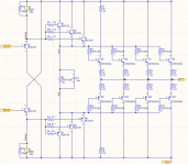
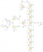
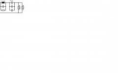
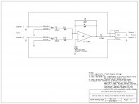
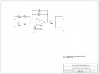
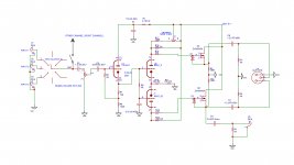
Such circuits have been designed long time ago. The most important and useful, yet the simplest is the DIFFERENTIAL AMPLIFIER CIRCUIT built by two working transistors. Such circuits are sold as an IC. Just get one and all problems are solved. Get it if you can, this is. Another schematic which passes through Australia when goes from LA to San Francisco, is the first part of the instrumentation amplifier. This is the first part of the instrumentation amplifier (with the resistors). There are two positively connected operational amplifiers in this circuit: OA1 and OA2. In the standard connection of each of them there should be a resistor from the positive pin to ground. Yes, but we do NOT have a ground, we do not have a middle point. Hence R13. In case R2=R4, the “middle” of R13 is supposed to play ground. So is the “middle” of the microphone. However, these are not connected. Not physically. Anyways, the operational amplifiers would work their ***** off in order to ensure the voltage of the negative pin of each of them is equal to the voltage of the positive pin.

Therefore, the voltage across the resistor R13 will be the same as the microphone voltage. This voltage comes from the output of the operational amplifiers through the voltage dividers: R2 and ½ R13 as well as R4 and ½ R13. In case R2=R4 is selected, and the equal value is said to be R24, then the gain of OA1 is (1+R2/(R13/2)) and the gain of OA2 is (1+R2/(R13/2)). The gain of the whole circuit is the sum of the gain of the two half circuits:

G=Goa1+Goa2

Substitute R2 and R4 with R24=R2=R4, therefore:

G=1+2R24/R13 + 1+2R24/R13 = 2+ 4R24/R13 = 2(1+2R24/R13)

The important consideration is the reduction of the error due to non equal channels would be brought to reduction of the differences of two resistors only. Resistors with very equal values and low aging are easily available and not so expensive.

In case of a different bias of the operational amplifiers, there will be a DC component at the output which can be gotten rid of by the capacitor in the microphone input of the amplifier after the pre amplifier. The requirements on the operational amplifiers are relaxed.

Current path (current return path) check: No current shall be drawn from the microphone. OA1 and OA2 have infinite resistance. Currents will fly from the outputs of the operational amplifiers. OA1 will get a current from one of the rails of the power supply and get it through OA1, R2, R13, R4, output of OA2, through OA2 to the other rail of the power supply. OA2 will get a current from one of the rails of the power supply and get it through OA2, R4, R13, R2, output of OA1, through OA1 to the other rail of the power supply. Thus there will be a full current path.

To check the current path is one of the most important checks in positively connected operational amplifier design due to lack of operational amplifier virtual ground point and infinitely high input resistance. Logically, current cannot pass through an operational amplifier input. Physically is another story.

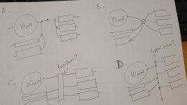
I haven’t thought very carefully over this schematic but I think this may work. To work or not to work is not very important because I haven’t invented this circuit and I cannot even lie I have. This circuit is the first half of one of the most well known circuits in the world: the so called Instrumentation Amplifier. There are two important variations of the Instrumentation Amplifier: with amplifiers at the front and with buffers at front. Most would use buffers at front to boost the input impedance. Buffers have a straight connection from output to negative input which gives them 100% feedback ratio and thus boosts the input impedance. In other words, whatever is displayed in the output will be present at the negative input and the operational amplifier will work in such a way as to provide such an output voltage to make the voltage difference between the negative and the positive pin 0. This is what the operational amplifier is designed to do. When you connect the output to the negative input, the voltage of the output which is the same as the voltage of the negative input (they are connected) must be equal to the voltage of the positive input. THERE IS NO OTHER WAY TO EQUALISE THE INPUT PIN VOLTAGES. THIS IS THE ONLY WAY THE OPERATIONAL AMPLIFIER CAN GO.

Think of the 100% number this way: In buffer mode, all the operational amplifier does is to repeat the input voltage and nothing else. This is done by the feedback which brings the output to the input as well as by the operational amplifier as a component which is in the straight track of the circuit. In amplifier mode, the operational amplifier does something more than just pushing voltage backwards: the operational amplifier, as a component connected in a circuit, amplifies. We pay with loss of input impedance in order to have amplification and yet high input impedance. When we do not have amplification we get a huge input impedance but there isn’t amplification.

Theoretically, one does not need power to amplify. One needs power only when one drives load. Theoretically, the losses in the operational amplifier are 0. There is power loss at the load only. Also, theoretically, there is no power loss at the source. So, the operational amplifier has been designed to amplify THEORETICALLY without power and only to take power from the power supply and give it to the load when the load so desires (consumes). Amplification is logical, not physical. When the word amplification is used, most often the word is referred to VOLTAGE AMPLIFICATION. These considerations also apply to current amplification BUT, obviously, do NOT apply to power amplification unless we talk power amplification without power consumption which is not very useful but, in theory, even so is possible.

It is important to note: PRACTICALLY the operational amplifier always consumes power for the internal operation of the operational amplifier being only amplification without power consumption at the output. Also, THE MORE THE OPERATIONAL AMPLIFIER CONSUMES THE BETTER AND THE FASTER THE WORK OF THE OPERATIONAL AMPLIFIER! Hence, for most applications, the more the better is OK. Better consume more power but have a better performance. In battery powered application, tough!


Microphone

>+
=
=
===

+
=
=
===

-
=
=
===

-
=
=
===

R2

R4

R13

-
=
=
===

+
=
=
===

+
=
=
===

-
=
=
===

OA1
=
=
===

OA2
=
=
===

Ui1

Ui2

Uai1

Uai2

I

Uo1

Uo2

Ui

Uo


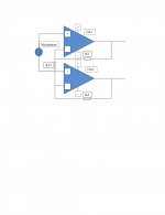
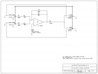
The schematic is rather misleading, although very simple. The misleading comes from the crossing paths of the two operational amplifier circuitries. The easiest mathematical (with a slight combination with physical) analysis is when it is assumed all voltages are positive to some imaginary ground which is far more negative than the most negative possible voltage, i. e. more negative than the negative power supply rail. This is physically OK because we can call any point a reference (a ground) point from – infinity to + infinity and perform our analysis and this analysis must work for all points. However, in case the analysis works for one, the analysis will work for all because the voltages and currents do nothing else but may change signs ACCORDINGLY with any change of reference. The word ACCORDINGLY is very important here. This means whatever changes, something else will change too to maintain the balance. Balance must be maintained not only because we have arbitrarily chosen a point but also because of the Kirchhoff’s laws: all voltages as well as all currents get neutralised. Move the point as you wish. All voltages as well as all currents will continue to neutralise. The same applies in regards to the values of the voltages and currents.

In the schematic, except from the assumption all voltages are more positive than the reference point (imaginary ground), values have been assumed as Ui1>Ui2, therefore Ua1>Ua2 and Uo1>Uo2. Also, remember the only and most important point of the analysis (another than Kirchhoff’s and Ohm’s laws bit of physics (electronics) in the mathematics): When an operational amplifier is connected with a negative feedback THE VOLTAGE OF THE POSITIVE PIN AND THE VOLTAGE OF THE NEGATIVE PIN ARE EQUAL AND THERE IS NO CONNECTION BETWEEN THESE TWO. True for an IDEAL operational amplifier. Ideal operational amplifiers have infinitely high input impedance, infinitely low output impedance, infinitely high internal gain and are infinitely fast.

So, the input voltages are called Ui1 and Ui2 and thus the microphone voltage is:

Ui=Ui1-Ui2

The positive pin voltages are called Ua1 and Ua2 and:

Ua1=Ui1
Ua2=Ui2

The output voltages are called Uo1 and Uo2 and the output voltage of the pre amplifier which will enter the amplifier thereafter is:

Uo=Uo1-Uo2

No current shall fly from the source (microphone) because of the huge input impedances of the operational amplifiers which is almost isolation from the point of view of the source (microphone) when there are negative feedbacks at each of the operational amplifiers.

Since Uo1 has been accepted to be higher than Uo2, a current I shall fly from Uo1 through R2, R13, R4, will meet Uo2 and go to the negative rail of the operational amplifier OA2. No current shall fly to the imaginary ground. Such is not physically connected. Just assumed to be in order to conduct the potential analysis in accordance with the laws of Kirchhoff and Ohm. This current I shall make voltage drops across each and every resistor the current passes through as per the Ohm’s law.

The Kirchhoff’s law says the sum of the voltage drops across the resistors the current passes through must be equal to the voltage across the two points between which the resistors are:

Uo1-Uo2=IR2+IR13+IR4=I(R2+R13+R4)

But

Uo=Uo1-Uo2

Therefore:

Uo=I(R2+R13+R4)

Also:

Ua=Ua1-Ua2=IR13 (this is the voltage between the negative pins of the operational amplifiers OA1 and OA2 which is the same as the voltage across R13 because the two points of R13 are connected to the two negative pins.)

But we have said:

Ua1=Ui1
Ua2=Ui2

And

Ui=Ui1-Ui2

Therefore:

Ua=Ui

But we have said:

Uo=IR2+IR13+IR4

And

Ua=IR13

Therefore:

Uo=IR2+Ua+IR4

But

Ua=Ui

Therefore:

Uo=IR2+Ui+IR4

This is the first relationship between input and output voltage. This is what we have been looking for. Once we have the whole, we will get the gain. There is current I in this relationship. We want to have only input voltage, output voltage and resistors (constants) in order to calculate the gain.

Thankfully, we have said:

Uo=I(R2+R13+R4)

Therefore:

I=Uo/(R2+R13+R4)

Now we have the current expressed as a function of the voltage. Before, we had the relation amongst input voltage Ui, output voltage Uo and current I. When we substitute the current we will get a relation between the input and the output voltages:

Uo=IR2+Ui+IR4

Therefore:

Uo=Ui+I(R2+R4)

Substitute the current and:

Uo=Ui+(R2+R4)Uo/(R2+R13+R4)

And this is the Input Output relation. In order to calculate the gain we need to work out the equation a bit in order to get it in shape: Output equals gain * Input or Uo=GUi. To do so, we need to have a multiplier in front of one of the voltages:

Uo-(R2+R4)Uo/(R2+R13+R4)=Ui
Uo(1-(R2+R4)/(R2+R13+R4))=Ui
Uo((R2+R13+R4-R2-R4)/(R2+R13+R4))=Ui
Uo(R13/(R2+R13+R4))=Ui
Uo=Ui(R2+R13+R4)/R13
Uo=Ui(1+(R2+R4)/R13)

Therefore the gain is:

G=1+(R2+R4)/R13

In case R2=R4= ½ R13, G=2.

In case R2=R4=R13, G3.

In case R2=R4=0, G=1. Physical check: We have two operational amplifiers with outputs connected to their positive pins. O o, buffers. Voltage of the output repeats the voltage of the input! True. The whole schematic is a buffer.

In case R13 is infinity (not equipped), G=1. Physical check. True. The output voltage goes from the outputs to the negative inputs and does not get divided. The availability of the resistor does not make a difference. The input impedance of the unfeedbacked operational amplifier is huge. No current flies. Even in case there was some curren, the current wouldn’t get divided between the resistor and the huge input impedance. (The division will be negligible.)

In practice, the operational amplifier needs some negligible currents in order to operate hence no input must be blocked by huge resistances. Anyways, huge resistance in the feedback is not good because the noise picked up by the huge resistance goes straight into the feedback path and screws up the whole stabilisation of the circuitry. Rule of thumb is 1MΩ which will provide enough current for most of the operational amplifiers and not so much noise. Best don’t go over this value, although there is such a possibility with most of the operational amplifiers.

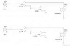
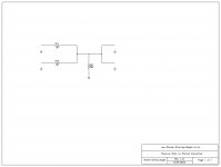
In this case, the source (microphone) would provide the current needed for the positive pin to work. This is why in other schematics positively connected operational amplifier must not be used without a caution where the current comes from and how much. Negatively connected amplifier may be preferable because the feedback brings current for the negative pin to work and ground provides to the positive. Yes, but then the negative resistor in parallel to the feedback resistor become the input resistance and the input impedance will not be so high. But the working current will be provided by the feedback. The input resistance will be for discharge of the microphone but not for throwing current out of the resistance.

This is illustrated below:


Microphone

+
=
=
===

-
=
=
===

+
=
=
===

-
=
=
===


In case of a positively connected operational amplifier, the necessary current for work of the amplifier is provided by the source (the microphone) and gets returned to the source (the microphone) through the rest of the circuitry. This current CANNOT be compensated for. Will result in signal loss. Hopefully this current is not so high. Operational amplifiers with input built by JFET (Junction Field Effect) transistors have extremely low input currents. Even a microphone is supposed to be able to deliver these.

The resistor, however, does not lead to signal loss, contrary to what I may have said. The microphone generates a current or a voltage (irrelevant) which, in case of current, will circle through the resistor and, in case of perfect amplifier, has nowhere else to go. The voltage has nowhere to go to and cannot be divided. The current may be divided between the low resistor and the huge input resistance of the operational amplifier which means the current will not be divide too.

There is only one problem with the resistor: in case of CURRENT (not voltage, contrary to what I may have said) and a low resistor, the voltage across the resistor will be incredibly tiny. A huge gain may be necessary to amplify. Worse, the noise across the resistor may be stronger than the signal. In this case, the resistor can be taken over and the microphone (in case of perfect amplifier) would work alike with an open circuit: the input impedance of the operational amplifier is huge and is alike isolation (air). So the microphone will provide the highest signal possible. Theoretically, the signal will be infinitely high because the microphone generates current which has nowhere to go and builds up an infinitely high voltage: Ohms law: current through infinitely high resistance equals infinitely high voltage. In practice, the microphone current will go through microphones internal resistance which is in parallel to the microphone. Perfect microphone would have this internal resistance infinitely high. Real ones have lower internal resistance. And this is why a resistor across the microphone will not result in signal loss when the microphone is perfect but with real microphones, this resistor is in parallel to the internal resistor, hence the signal loss.

What I would like to figure out is what happens when I try to force the microphone to operate current inside the microphone (through the internal resistance). I am sure I would get a huge signal BUT I am sure I would get a huge noise too.

The rule of noise is: noise levels are huge across large resistance and tiny across tiny resistances. When the cable is taken into consideration (although shielded) one may as well find to have built an antenna instead.


Microphone

+
=
=
===

-
=
=
===

+
=
=
===

-
=
=
===


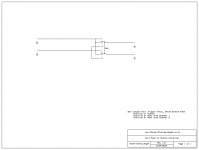
A GOOD IDEA WOULD BE TO TRY TO DO THE CIRCUIT WITH INVERTING AMPLIFIERS THIS IS WITH THE NEGATIVELY CONNECTED OPERATIONAL AMPLIFIERS.

Most of the necessary current which must enter the inputs is supplied by the output of the operational amplifier through the feedback resistor.

As a gross generalisation: when possible, always use the inverting amplifier schematics. For microphone pre amplifier where there is a discharge resistor across the capacitor anyways, use the inverting amplifiers schematics and calculate R1||R2 to be equal to whatever the discharge resistor is desired to be.


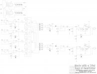
Pseudo filtering considerations:


Microphone

+
=
=
===

+
=
=
===

-
=
=
===

-
=
=
===

R2

R4

R13

-
=
=
===

+
=
=
===

+
=
=
===

-
=
=
===

OA1
=
=
===

OA2
=
=
===

Rm

C2

C4


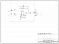
In case of a noise problem, a resistor Rm can be put across the microphone. Thus, current will cycle there and not go to the rest of the circuit. This may reduce the sensitivity of the microphone, i. e. result in lower voltage of the microphone. A filter capacitor can be put across the microphone too but the unknown parameters of the microphone will result in impossibility to know the value of the capacitor to adjust the cut off frequency to 25KHz.

C2 and C4 are filtering capacitors which partly “shunt” R2 and R4 at frequencies higher than the cut off frequency which is to be 25KHz in this case. However, this cannot fully filter the frequencies higher than 25KHz because the gain of the whole circuit gives value of 2 when R4 and R2 are shunted. In case we substitute 0’s for R2 and R4 in the formula of the gain, the formula gives a value of 2. Physically, when R2 and R4 are shunted (replaced with a short connection) we achieve two separate buffers similar to the Instrumentation Amplifier with Buffers and the gain is 1.

Attachments

  • Test4.jpg
    Test4.jpg
    142.6 KB · Views: 192

Audio Pre Amplifier

There are many different sources of audio signals these days: many different microphones, iPods, iPads, Cellular Telephones, PC Audio Cards, MP3 Players, Guitar Hum Buckers, Keyboards, etcetera.

The analogue outputs of these are not standardised. As a consequence of which the sound level differs tremendously as depends on the device used. For example, there are many microphones which can barely be heard with the same settings with which other microphones perform normally. Also, there are many devices which have microphone inputs with different parameters. The same microphone may not be heard when connected to a given device even at highest possible volume adjustment while this may perform well with other.

The same can be said for amplified PC speakers. Either the PC output or the amplifier of the speakers may be too weak to perform to the expectations.

I have, therefore, done a simple device which uses simple and basic electronics circuitry which is a three channel pre amplifier and can be used in many combinations thereof. One of the most useful application may be as a microphone and amplified speaker pre amplifier.

I have been using this device and the sound performance of the PC has been improved tremendously.

For those interested, please visit
www.Steven-Stanley-Bayes.co.cc and click on the link "Pre Amplifier".

Simple Stereo Microphone

PC's' sound cards usually have two independent stereo channels for microphones with phantom power on each of them, convenient for electret condenser microphones.

The word stereo, in this sense, describes the electronics. The two microphones may have similar signals, yet, each of them goes through a separate channel and is recorded by the PC and stored as a separate track.

In terms of the microphones, whether they are omnidirectional or not, when they are close to each other, the difference would be negligible, yet, there may be some :

* caused by a different volume level, when the sound source is closer to one of the microphones than the other
* caused by a phase difference ( different delay ) because of the same reason ( this is negligible )
* caused by a phase shift ( different delay ) because of the difference in the microphones and the channel parameters ( this is also negligible )

All of these may not be possible to be heard by a human.

However, in a case of a stereo microphone, the third cause, the difference because of the manufacturer's tolerances of microphones and channels, is even more negligible as this difference will not be present in the electronics but in the human head where the two channels are combined. Humans are not so good to be able to here any such of a difference. In the worst case, any difference will be worked out by the human brain as a 3D positioning and not as any distortion, nonlinearity, etcetera.

Some PC microphones have only one electret condenser microphone which they connect to each of the channels and some cannot cover the whole audio range of 20Hz to 20KHz. Some have lower sensitivity than others.

I have, therefore, made a stereo microphone with two electret condenser microphone where each of the microphones takes phantom power from and displays the signal to only one of the channels. I have used two CMA 4544PF W which are 20Hz to 20KHz, 3V to 10V microphones with good sensitivity.

When the PC is set up to 100% microphone level and 0% microphone boost, the signal is excellent when one talks 60cm away from the microphones and very good when one is 1m away.

Attached are simple schematics and more.

Attachments

  • Simple Microphone.jpg
    Simple Microphone.jpg
    48.2 KB · Views: 190
  • Simple Microphone Picture Front.jpg
    Simple Microphone Picture Front.jpg
    510.6 KB · Views: 190
  • Simple Microphone Picture Back.jpg
    Simple Microphone Picture Back.jpg
    560.5 KB · Views: 179
  • Simple Microphone Picture Top.jpg
    Simple Microphone Picture Top.jpg
    443.5 KB · Views: 181
  • cma-4544pf-w.pdf
    cma-4544pf-w.pdf
    299.8 KB · Views: 72

Distortion by Amplification

I have designed, made, improved and tested a very simple, transistor based distortion effect for guitars ( can be used for anything, I guess, but I have so far never tried to use distortion on anything else than a guitar ).

I have written a simple document which is written at a very basic level and explains why 2 and 2 is 4 and not five. I will be happy to have people who want to read the whole document, but, most of the people would only want to read the addendum where the schematics and the pictures are.

Here is the document. Please, inform whether the link can be open by anyone : Distortion Amplification - Google Drive

Simple Idea of "Fully" Digital Microphone and Guitar

I have been having an idea for as full digital approach to everything connected to sound as possible. Hence, I am puzzled why there are still analogue devices. The only reason I can think of is because of the noise and lousy power supplies of standard digital electronics (PC's for example), although I consider the noise is far higher than the audible range. Another reason may be the transients generated by switching power supplies and digital devices (high power processors).

However, there are ways to fight these. Standard filtration and multi capacitor arrays at the power source as well as capacitors spread around the PCB in a "digital electronics" fashion (the other way around: protect the circuit from the coming noise as opposed to protecting circuit from the emitted by an IC noise) with parallel of a few electrolitics, a few tantalums, a few ceramics silver micas and whatever they have there, starting from huge values and decreasing to pF.

There are variations of zeners with various commercial names as mosorbs, etcetera which can be effective in the struggle against transients.

However, the reason for this article is to invoke your conversations in the sense of as early digitization as possible and make you discuss all advantages and disadvantages thereof.

So, the idea is very simple: take any kind of microphone, bring a nice battery; totally disconnected from the noisy world to the microphone; get your pre amplification and amplification there; get a nice ADC and digitize the shite out of the signal; in case so desired, digitally process the signal: filter and protocolise (make a simple transmission protocol to send the signal without too many errors). Filtering is best to be left to the other equipment. Digital compression of the transmitted information may not be necessary because of the low maximum frequency of the audible sound 25KHz. May I, please, suggest 30KHz, so even the poshest violin player in London Philharmonics is happy.

Then send the bits and bytes to the USB and you are in business. Sure Microsoft can do a simple sound processing software as well as many around. Simple and no speed is required.

One way to send the bits and bytes is through nasty and noisy radio transmission, another is through a simple cable (better be coaxial) and, of course, the best way is by light: laser diode and fiber optics cables.

One way to market is to tell the singers there ain’t gonna be no cables. They don’t care what the sound quality is, definitely not after a few beers when their voices are all over the place and so are their years, not to mention their brains.

Now, the same applies to the guitars. Can you imagine how nice it would be to plug a simple battery(ies) into the guitar and get the digital goin’ all over around. Then, with a few clicks of the mouse (usually 1) I can have or synthesise any sound I’d like. I do not like electronics sounds (meaning the field of music called electronics) but you probably do. However, I like distortion (the guitar effect) and I would definitely use such by clicking the distortion icon.

And all this (software and hardware) is so inexpensive yet so high quality, I can even make a professional CD and try to sell the CD in London’s subway (The Tube)!

There is one problem though: I will be the only one to purchase this CD. The good news for y’all is: this is the case NOT because of the technical quality of the sound.

May I, please, ask you to comment on the most important question: The advantages are obvious. What are the disadvantages? In case of a lack thereof, why can I not purchase a system alike from the Chinese shop for a dollar or two? (Far more than what the manufacturing price of such a system is.) The sense of this question is why the guitar and microphone manufacturers do not do this on daily basis. Assuming they are stubborn (which they are), why do the Chinese not manufacture standard separate devices for guitar/microphone.

Also, before your human loving angry response to exploitation of inexpensive Chinese labour, take a look around and say how come I can purchase so many complicated things around for a fistful of dollars and I can’t get a microphone/guitar digital system whose manufacturing price with brand name components manufactured in Taiwan is 25c?

Volume, you’d recon. You are right. There is a huge demand for this kinda systems. Everyone talks and everyone rocks!

Can I rephrase the main question: Do you see any reason why such a simple system (device) is NOT manufactured?

What say you?

Simple Amplifier

This is a schematics which I think I have just invented but I am not sure whether the circuit has not been invented before. This circuit uses a common emitter connection of the transistor(s) T1 and T2 and a common collector connection with the transistors T3 and T4 and the operational amplifier acts as a transistor stabiliser and source. In other words, the “analogue logic is carried out by the operational amplifier and the power as well as voltage conversion is carried out by T1, T2, T3 and T4. The most important application of this circuit is where the operational amplifier (whether buffered by power transistors in the feedback after the IC output or not) cannot provide the necessary output voltage because of the limitations of the maximum supply voltage of the operational amplifier. Hence, a separate power supply can be connected through resistors Rc1 and Rc2 to the collectors of T1 and T2 (common emitter) and without any resistors to the collectors of T3 and T4 (common collector). The beauty of this circuit as opposed to the standard common emitter or collector discrete transistor amplifier circuits is the feedback is after the transistors and therefore the output voltage does not depend on the transistor circuits but on the ability of the operational amplifier to maintain the voltage on the plus input to be equal to the voltage of the minus input, which ability is rather high. Also, the output impedance of the whole circuit with transistors before the feedback is much lower than the output impedance of a common collector amplifier built as a separate circuit and not related to the operational amplifier (i. e. positioned after the feedback).

Basically this whole circuit is a simple externally boosted operational amplifier. The output voltage can be bigger than the range of the operational amplifier but this is not a problem because this output voltage will be divided and the result of the division will be and must be within the range of the operational amplifier. Rb can be omitted physically, and, for simplicity, these explanations will be provided when Rb=0 is assumed. Thus the operational amplifier IC output pin will swing between -0.7 and +0.7 running T1 and T2 and depending on the voltage current characteristics of their base emitter junctions for control. Rb can be inserted in order to enlarge the control range and thus reduce the sensitivity of the control but the well feedbacked operational amplifier will be able to maintain the necessary base emitter voltage even without Rb because of the high level of precision of the control ability of the operational amplifier. As depends on the IC’s output pin voltage, one of the transistors (T1, T2) will go more open or more closed whilst the other one does the opposite: goes more close or more open. THE IMPOSTANT THING TO NOTE IS THE EMITTERS OF T1 AND T2 ARE CONNECTED TO GROUND WHICH GIVES THE OPERATIONAL AMPLIFIER TO CONTROL THESE AS THE IC PIN OUTPUT VOLTAGE IS REFERENCED TO GROUND AND NOT TO U2+ NOR U2- WHICH VOLTAGES (U2+ AND U2-) THE OPERATIONAL AMPLIFIER MAY NOT BE ABLE TO ACHIEVE AT ALL. Operational amplifiers have a limit of the maximum supply voltage due to internal design limitations (unless the operational amplifier has been specifically designed to work under hifgh supply voltage in which case, some parameters y have been sacrificed to have achieved this ability). For example, the iconic TL084 has been designed to be able to perform with maximum +/- 18V supply voltage (U1+=18V max and U1-=-18V min). TL)84 is not rail to rail amplifier and there isn’t a true rail to rail amplifier as far as I know although the companies would call them so because there is just a tiny bit more to go to become real to reel (real reel to reel). Usually, the operational amplifiers would go all the way down to negative but will be shy of a bit to reach the positive supply reel. TL084 can go from negative to positive -1.5V. In case of maximum power supply of +/-18V, TL084 would be able to go from -18 to + 16.5V at the IC output pin. When symmetry is needed, TL084 would be able to swing the output (to wave the dick on the beaches of Florida) from -16.5V to +16.5V. A perfect sine with an amplitude of 16.5V would have an RMS value of Amplitude * 0.707 which, in this case, is approximately 12V. The square of this RMS value divided by the load resistance RL would give the maximum power a circuit with output of +/-16.5V in amplitude would be able to give even when no limitation of the maximum current exist. Thus, a 4O loudspeaker will suck twice as much power out of an amplifier with a given output voltage as an 8O loudspeaker ONLY IN CASE THE AMPLIFIER CAN PROVIDE THIS POWER, i. e. maintain the voltage while blowing a current with an RMS value of 12VRMS/4O=3A. An amplifier with a +/-16V output will then be able to provide a maximum of 36W RMS when connected to a 4O speaker. REMEMBER: THE AUDIO AMPLIFIER IS A VOLTAGE SOURCE NOT A CURRENT SOURCE. THE AUDIO AMPLIFIER GIVES A VOLTAGE AND TRIES TO DO THE BEST POSSIBLE TO MAINTAIN THIS VOLTAGE AT ANY CURRENT SUCKED OUT OF THE AUDIO AMPLIFIER TO THE MAXIMUM CURRENT POSSIBLE. I.E. AUDIO AMPLIFIER WORKS IN REGIME OF A MAINTAINED VOLTAGE NOT IN A REGIME OF A MAINTAINED CURRENT.

So, is there any way to have an amplifier with maximum amplitude +/- 16.5V to give more power when a load of 4O is connected? NO! There is only one way. Get more voltage. But the operational amplifier does not allow for more voltage. Then run the operational amplifier up to this voltage and build a circuit controlled within this range which can give more voltage because the circuit will be supplied by a higher voltage while only controlled by the lower voltage possible to be achieved by the operational amplifier. So, put, say +/-5V supply to the operational amplifier (whichy will be able to reach a symmetric output of +/-3.5V and then build a separate common emitter circuit which will be supplied by, say +/-60V and will run the loudspeaker. Or you may not have an operational amplifier at all. However, the circuit with an operational amplifier and a feedback after the power transistors has a lot of advantages previously discussed.

The common emitter connected T1 and T2 amplify and invert the signal of the operational amplifier and display this at their collectors which, in turn, drive the common collector followers T3 and T4 for which reason Rc1 and Rc2 must have such values as to allow the necessary current to fly through the base emitter junctions of T3 and T4. T3 and T4 do the opposite “ground : supply” consideration: while T1 and T2 take one signal, reference this signal to ground and split (“uncombine”) the signal to provide two outputs at their collectors, T3 and T4 take these two outputs as their inputs, reference these to U2+/- (T3 to U2+, T4 to U2-) and combine them again into one output which goes to RL.

The output voltage at RL will be much higher than the operational amplifier can handle. This means, there will be periods when the operational amplifier will go in saturation and will not be able to provide control and the same will happen to the output. This is why, the R2, R1 arranged feedback divides this output voltage to bring the input voltage coming from the output through the feedback in a size possible to be handled by the operational amplifier. When ground is applied to the negative input, the operational amplifier will do such as to have 0V on the positive (virtual ground). Thus a cureent of Uin/R1 will fly through R1 which can go nowhere but through R2, thus the output must be adjusted by the IC in such a way as to allow this same current to fly through R2. But one of the ends of R2 is connected to the positive pin (virtual 0V) which has 0V because the negative is connected to ground and the operational amplifier does nothing else but adjusting the output to make the two inputs equal. The other end of R2 is connected to the output Uout. Therefore Uout must be adjusted by the operational amplifier to be:

Uout/R2=Uin/R1

In order to have the current fly through, or to “suck” the whole current to the output.

Rewrite the formula:

Uout/Uin=R2/R1 which is:

Uout=Uin R2/R1

So, the output is equal to the input multiplied by a coefficient R2/R1 which coefficient is the gain G=R2/R1. NOTE: BECAUSE OF THE R2, R1 FEEDBACK Rc1/2 DO NOT HAVE ANYTHING TO DO WITH THE GAIN.

Will the operational amplifier be able to adjust the output this way? Assume the input Uin is positive, then the current flies from Uin through R1 to the positive pin (virtual ground), then cannot go nowhere else except through R2 and then continues to the output to pass through RL in part and through T4 to negative power supply U2- and then through the U2 power supply to the common ground between U2 U1 and Uin which must exist otherwise voltages will fly all over the place without any reference with each other.

In order for this current to be able to fly, the operational amplifier must adjust the output voltage to be negative and with a certain value. Because the operational amplifier is feedbacked, the operational amplifier will be able to provide the value of this voltage for sure as long as the feedback is stabilising and not generating feedback, means negative and not positive. This is the ONLY condition for feedbacked systems (the only qualitative (logical) condition, not quantitative (amount of how good the feedback is)). (This can easily be explained but not now.)

So, do we have a positive or a negative feedback? The only thing which can say so is the signs of the input and the output. In case the signs are the same, we have a positive feedback, otherwise, we have a negative.

Yes, but the feedback goes to the positive pin, this means positive?!? In most cases, yes but, not in this case. The output of the IC is INVERTED by the common emitter then REPEATED (not inverted) by the common collector. Therefore, the output of the schematic is inverted as compared to the output of the IC. Assume, we follow the standard procedures and put the feedback to negative. Then the IC will invert Uin the same way as the standard inverting operational amplifier circuitry does. Then the common emitter will invert again. Therefore Uout will have the same sign as Uin. Now, assume we connect the feedback to the positive pin (as shown). Then the IC does NOT invert the signal but the common emitter does, so the output Uout is opposite in sign to the input Uin which means we have a NEGATIVE (STABILISING) FEEDBACK although we connect to the positive pin. This is because we have an inverter immediately after the IC and before the point where the feedback is taken from.

Generally, this schematic is the SAME as the standard inverting amplifier as far as the logic of the way the schematic works is concerned, just there is an invertor at the end of the operational amplifier thus the feedback must go to the positive pin.

The same schematic may be connected to the equivalent way and logically the same as the standard noninverting amplifier, then point of R1 where Uin is applied now must be grounded and Uin must be applied at the positive pin. The derivation of the formula for the gain is the same as the derivation of the formula of the gain of the standard noninverting amplifier and the gain is: G=1+R2/R1

Any ingenious design? No. The circuit is the same as:
a) The standard amplifier, just the output is additionally inverted and more powerful and takes different power supply, yet has a SINGLE GENERAL FEEDBACK which gives the best parameters possible at the huge power output.
b) The standard amplifier with boosted output with common collectors, just the output is inverted and power is taken from a separate power source
c) The separately built circuitry by a standard operational amplifier, a separate common emitter and a separate common collector each of them with their own feedback wherever whatever necessary. (Common emitter does NOT require an AC FEEDBACK only DC. Common emitter is straight, non regulated amplifier.) The parameters of this circuitry will be worse.
d) Same as c) but with a general feedback as well as separate. Works OK but the parameters will not be as good as single general feedback. Mainly the speed of control as far as I can think. This is also because the straight gain will be lower which also leads to higher output impedance and lower input and is a fuckin’ waste of components and assembly.

Anyways much ado for notha. Also, much a do for notha. I have not though carefully through this schematic, so you must.

Attachments

  • Test31.jpg
    Test31.jpg
    166.5 KB · Views: 945

Standard, Low Power, Three Point, Audio Power Supplies : ±15V, ±9V and ±5V

I have made two standard, three point, power supplies, 200mA each, which may be suitable for audio. One of them provides + - 15VDC and the other one provides + - 9VDC and + - 5VDC.

The first power supply is universal and can work with 120V AC RMS mains as well as 220V AC RMS and 240V AC RMS mains.

The goal has been to make low noise, low output impedance DC audio power supplies. Because standard approaches ( L7815, L7915, LM317 and LM337 ) are used, brutal force has been used to reduce the noise by the use of high value, low ESR, Japanese audio capacitors.

I do not have a scientific way to measure the noise, but, I cannot hear any even at super high gains.

I have written the projects in a document which contains the full schematics and, I hope, satisfactory explanation. Here is a link to the folder which contains the document made with OpenOffice and called Power Supplies.doc :

Power Supplies - Google Drive

Please, inform of any errors, etcetera.

Simple Mono to 2 Speakers

I have been asked a lot of questions on mono to 2 speaker a. k. a. mono to stereo and I have decided to make this publication, therefore.

Attachments

  • Passive and Active Mono to Stereo Converters.doc
    Passive and Active Mono to Stereo Converters.doc
    27.5 KB · Views: 64
  • Active Mono to Stereo and Stereo to Mono Universal.jpg
    Active Mono to Stereo and Stereo to Mono Universal.jpg
    257.3 KB · Views: 187
  • Active Mono to Stereo with Front Switches.jpg
    Active Mono to Stereo with Front Switches.jpg
    187.7 KB · Views: 187
  • Active Mono to Stereo with Switches.jpg
    Active Mono to Stereo with Switches.jpg
    163 KB · Views: 165
  • Active Mono to Stereo.jpg
    Active Mono to Stereo.jpg
    142.2 KB · Views: 166
  • Passive Mono to Stereo.jpg
    Passive Mono to Stereo.jpg
    106.5 KB · Views: 156
  • Wire Mono to Stereo.jpg
    Wire Mono to Stereo.jpg
    137.6 KB · Views: 91

Fully Differential Amplifier Power Stages

I have tried but been unable to find an elegant solution on how to use fully differential amplifiers to drive feedbacked output common collectors and other output transistor combinations.

In case anyone can correct the mistakes I may have made or suggest new ideas, anyone is welcome.

I have some more schematics, some of which I can publish when I update the file.

However, what I try to achieve is to make people think of whether fully differential amplifiers can be elegantly be used to drive power stages.

See attached. Whoever wants to skip the introduction can directly go to point 2. Some Schematics.

I am sick and tired of these for now as I have tried to find an elegant solution for a week. On the top of everything, I cannot publish the doc file because the forum does not allow big files. I had to delete the pictures and upload them separately. The names of the figures, however, stay in the file. Just the figures are outside.

Universal Audio Amplifier

I am to publish the documentation when ready.

This is a simple, standard electronic circuitry, off the shelf part, inexpensive and may be found useful universal audio amplifier which allows for most any configuration of the 4 channels. All can be made mono and displayed on one of the stereo outputs only, or on the two stereo outputs. Any can be combined with any and displayed on any of the two outputs. Thus, a possible application is to play music from, say the "Immigrant Song" on the two channels in stereo fashion while playing the solo and displaying this on one of the outputs and singing and displaying the voice on the other. Or the music can play on one of the channels in mono fashion while the guitar and the voice are on the other thus allowing a direct competition to Robert Plant and Jimmie Page.

This is achieved very simply NOT by electronics but by simple configuration single pole double throw switches as well as a few on off switches.

THE CIRCUIT HAS NOT BEEN TESTED BECAUSE THE CIRCUIT HAS NOT BEEN BUILT. THE AVAILABILITY OF THE PARTS HAS BEEN CONFIRMED. THE CIRCUIT HAS BEEN DONE OVERNIGHT AND THERE MAY BE SOME MISTAKES ALTHOUGH SUCH ARE NOT EXPECTED BECAUSE OF THE SIMPLICITY AND THE STANDARD APPROACH. IMPROVEMENTS, CORRECTIONS, COMMENTS, SUGGESTIONS ARE POSSIBLE AND WELCOME.

Attachments

  • Universal Audio Amplifier.jpg
    Universal Audio Amplifier.jpg
    306.3 KB · Views: 2,507

Transistor Based Push Pull Preamplifier

I have made a transistor based push pull preamplifier and have written a document.

In the document, two approaches have been discussed : the made one, with standard common emitter capacitors and the better one, the one without standard common emitter capacitors.

The circuit without emitter capacitors provides gain and buffer like linearity. The price to pay is a gain dependent maximum output ( and input ) amplitude.

Yet, because of the advantages, I prefer the circuit without emitter capacitors, which is a standalone transistor circuit with a local feedback and without a general feedback from the very output to the very input. The local feedback circuit, however, provides performance similar to the common collector buffer.

Of course, because of a lack of differential amplifier, at high gains, the power supply same phase noise is also amplified, but, by a lower gain than the signal gain. At low gains, this noise is attenuated, but, not by much.

Of course, with a provision for high inputs, such as 4.35V, the circuit does not reach the rails and, at high gains, the maximum output amplitude can reach 10V with +- 15V power supply.

Again, please, note, this output can be achieved at high gains. At lower gains, the output is lower, but, the dependence is not linear, thus, only gains - 1 through -3 provide rather low outputs ( 5V through 6.67V ).

I do NOT have linearity analysers and oscilloscopes. I only have a simple, inexpensive multimeters and ears. By ear, the sound is fantastic and the noise is OK. With a battery power supply, the noise is not bad even at the maximum gain of around 400!

I have not installed, but, provided room on the PCB to put large electrolytic audio power supply capacitors. These would reduce the power supply cable noise significantly as with other projects.

The document became huge. There is no way not to have made any mistakes. An attempt has been made to turn all stones around, but, of course, I may have forgotten some. An attempt has been made to provide only logical explanations and not useless terms. Of course, some things may have not been explained well. ( Well means by logic and simple language only. Logic is science. Logic is not sense. )

Thus, please, report whatever you have found in this sense.

Here is the link to the document ( the schematics and pictures are in the addendum ) :

Transistor Based Push Pull Preamplifier - Google Drive

Also report in case of any problems with the link and the document download and ability to view.

Help! Connector ( Plug and Receptacle ), 3 Pin, >= 20A Needed for Audio Power Supply.

Help! Connector ( Plug and Receptacle ), 3 Pin, >= 20A Needed for Audio Power Supply.

I have been trying to find an audio power supply connector with 3 ( or more ) pins, which is an industry standard. However, looks like, such standard is not available. There are standard DC connectors, usually, used in wall adapter power supplies for single voltage power supplies ( positive and ground ), but, I have not been able to find a standard three pin connectors for positive, negative and ground and for AC ( before and after a transformer ).

So, the ideal connector is :

1. AC and DC rated.
2. >= 20A.
3. >= 35V.
4. Metal, possibly, Aluminium or Copper. Plastic in case metal is not available.
5. Screw cap.
6. Panel mount receptacle with thread.
7. Female pins on the receptacle.
8. Plug with a threaded cap.
9. Male pins on the plug.

In case there is not such, which one is as close as possible?

I have had a look at some Lex connectors, TE Connectivity connectors and high current banana plugs. I am not sure whether there are any with this description.

Chinese OK, although, not preferable. Made in China by big non Chinese companies preferable.

Please, help! In case you have used any plugs and sockets >= 20A, please, inform.

WD25t with cheaper tweeter

Hi,
After then years away from diy stereo (previuous efforts were from kits so I didn't have to design anything. I've decided to build a pair or 'keepers for life''. Decided on the World Design's WD25t, but with cheaper tweeters. The originals and the EX updated version are £250 each. I'm looking at more £40 to £100. The Seas 27TDFC seem at match as they reach into the lower frequencies needed for the xo with the Seas A26RE4 10" driver, though the tweeter is 6 ohms, whereas the driver is 8, so not perfect. But neither was the EX's Millennium tweeters, also at 6 ohms. I don't know if it's a big deal in designing a xo, but I imagine that having drivers with the same impedance is a good start.

Has anyone experience with this build using cheaper tweeters? I have no idea how to design a xo, though I am learning during this pandemic.
In fact if anyone has any advice or opinions on the WD25t speaker, please leave a comment.
Also, has anyone paired these speakers with a low watt (6/ch) amp? My current old Tannoys have an spl of 89dB, and my Bottlehead SEx amp can give an almost decent volume @ 2w/ch in my smallish room. So basically, what's the spl of the WD25t and do they sound good?
If anyone has alternative suggestions for speakers builds, I'm all ears.

V-Cap CuTF and AN Copper Film caps for sale

I have following used film capacitors for sale

V-Cap CuTF 0.33uF 600VDC set of 4, Euro 240

Audio Note UK Copper foil Mylar in Oil 0.22uf 630V set of 2 : Euro 30

Shipping would be 10 euros within Europe, other areas please ask.

Shipped from Vienna Austria

I am clearing my drawers as I am getting ready to move in about a couple of months.

Attachments

  • IMG_1296.jpg
    IMG_1296.jpg
    1 MB · Views: 406
  • IMG_1300.jpg
    IMG_1300.jpg
    1.1 MB · Views: 399

Toroid Power Transformer: How I wound my own.

I bought a surplus toroid transformer from E*ay with the primary I needed and a heavy enough secondary for filaments.
I started stripping wire: Fortunately the primary was closest to the core, followed by a high current, lower voltage winding.
I kept checking the voltage while stripping the high current secondary until I got the filament voltage I needed.
I put fiber ( I used automotive gasket material) to give me a smooth surface and electrical isolation for my HV secondary.
I bought two spools of magnet wire after estimating my current and length requirements, and made a fixture to move the wire pair to a bobbin.
It took several days to wind the secondary: After going around the toroid enough to obscure the fiber, I added a ring of masking tape so I could see and keep my spacing even.
I also added a separate 12 volt winding for control and possible digital features to my future amp.
After testing, I enclosed the transformer in a pair of steel heating duct covers for magnetic shielding and to provide a means of mounting.

Tiny TPA3132 50W amps

Hi,

Here's a miniature amp design I've been working on based on the TPA3132. Board size is 25x38mm (1"x1.5"), with holes to accept M3 mounting screws.

Input and output terminals are 100th (2.54mm) headers. One can either source some female header sockets with a sufficient current rating, or just solder to the terminals directly. Inputs are single-ended.

They sound nice, great detail and very clear. They have bootstrap snubbers, among other mods from the standard design. I'm offering it with either 20dB or 32dB gain. The 20dB option has slightly lower rolloff, and seemingly better detail but I can't be sure. I'd recommend the 20dB option for home use, and 32dB for portable speakers.

Please note that one must not expect 50 "usable" watts. At this power level, the THD rises enormously, and is basically unusable. However, one can expect 10 real watts (8 ohms) without problems. For more info, please consult the TPA3132 datasheet.

Also, it does actually run fine on 5V. Don't expect much power output though.

They are available (with full specs) at my bigcartel shop: IO390's stuff - 50W amplifier V2

Price is £21.99, shipping to the UK is Royal Mail 1st class (93p), everywhere else is £3.50. Shipping to EU is 3-5 day, everywhere else is 5-7 day. For faster shipping options, please contact me.

Some pictures:

U7ttKIul.jpg


ZVyHQuKl.jpg


2UxlYSwl.jpg


9Lb58xnl.jpg


Instruction manual is attached.

Attachments

Question regarding TU 8600 power side

All--

I pulled the ALPs pot from my TU 8600 to make it a stand alone amplifier.

Now that I have a hole in the front of my chassis it's time to fix that! I have a nice VU meter that will fit almost perfectly in the spot where the ALPs called home.

I have a nice little PC board with a voltage regulator that converts AC 120 to 6, 9, or 12V to power things like my VU backlight.

Which would you do?

Option 1: Run a separate AC mains power cable from the outlet to the VU meter and the PC board (this works in my tests).

Option 2: Tap the AC line in on the Elekit to feed the VU pc board to pull off 12 volts to run the light.

Option 2 would be cleaner in that I don't have to have a second power plug going into the Elekit, but I'm not sure about whether it would be taking juice from what the amp itself needs. The load is small, but I defer to the experts.

THANK YOU!!!

YouTube Music Channel

Hi,

I like to share with you my experience with music streaming services. Currently, I get subscriptions to both, Spotify and YouTube (hence get Youtube(YT) Music inclusive as well).

1. The sound reproduction from YTMusic is superior to Spotify in general.
2. In addition to YTMusic I get all services from YouTube uninterrupted.
3. You get access to many types of music from YT Music e.g Nelson Riddle and old music recorded from Vinyl. Obviously, you can't get the current crop of releases. Fellow music lovers do try or experiment with it.

All in all, I get more value from YouTube than Spotify. My 2 cents worth of contribution. Any comments welcomed.

BTW I don't subscribe to any other services, eg Netflix, etc.

Newbie of All Noobs Asks for the Secret Knowledge

Forgive me. I am the noob of all noobs. Those of you without patience for such should save themselves the trouble and flip the channel. Being an audio equipment lover who came to it back in the early 80s, I got away from it while I got established in a family and professional life. Now I find myself on the other side of the curve with a nearly empty nest and a little time on my hands. And so I have come to circle back to this old girlfriend, but found that my old stuff pulled out of storage-- NAD 3230, Alison Acoustics 8s and a mid-70s Dual 1219 my dad gave me -- are all pretty hobbled at this point.

I have been lurking for a bit around in the Pass Lab neighborhood bar here for some time since hearing about the ACA a few years ago and hearing the J and J2 a friend turned me on to. The idea of building my own decent audio equipment that bears some signature of all this beautiful stuff is more than I can resist and so here I am looking to get rolling. I am a noob for sure, but I come from adventurous stock and so here I am jumping in whole hog as we say in Nebraska.

My end goal I suppose is to get a pre amp in place with a couple simple mono blocks and drive some sort of speakers, all of which in the end I will have built myself. So: I have the ACA in hand as a starter project. If I figure it out, I will get another and make them monos. I need a pre-amp as well, and so I also have the Korg B1 amp project sitting here in a box. I figure all of these will get me rolling. If I want to upgrade at some point I suppose I will.

Here's the problem for guys like me:

The kits and instructions you guys have all put together are so good. I have been through them in my mind, and I have no doubt I will be able to put them together. I can follow instructions that are no harder than a Lego set. That's great, and I am thankful.

But there is another side to this: there is a way in which you have made it all too easy for a noob like me. As a result, I don't sense that I am learning what I need to learn. I have been reading the site for sometime and trying to make sense out of the basic language of (1) electronics; (2) audio signal jargon and so on. I am catching on to some of it, but I am still at a point where the language inside the discipline is a real challenge. All you guys living in Athens may forget what it is like for those who don't speak Greek.

And so I fear that when I return to the list from building some of the simpler stuff to the list to do some things that are a little more advanced -- that bi-amp active crossover project is very tempting for my plan to build some speakers I have in mind, for example -- I am concerned that I won't understand the secret language you all speak so easily to one another.

So here is the newbie who is not an-electrical engineering PhD question: where do I go to get the basic intro to the language being used? Where do I get the keys to the secret knowledge? Send me there. I promise I will keep my head down and do as I am told.

Bonesthrower
Lincoln, Nebraska

Psu for Tpa 3255 100w 8ohm speakers

Hello everyone!I just got aiyima a07 Amp ,also recommended by a seller (aiyima)psu which is 48v 7,5a. However my speakers are 100w rms 8ohm stereo.Do i need that kind of power from psu for 8ohm?Psu is ok, pleeeenty of power but standby 12w bugging me a bit.I had tpa 3116d2 previously with 24v brick psu and it was using only 2w in standby mode.Can somebody tell me how much power i actually need for my 100w 8R stereo speakers?Thanks a lot.
BTW i dont know if that matters but i have also aiyima T5 preamp connected, it strentghten the signal little bit as well i think..

Pass D1 - using i2s input

Dear all,

First off, if this is in the wrong section (digital line instead of pass labs?) forgive me.

I have a pass D1 that is configured for SPDIF input, I think it was on a version by spencer(?) back in the day. I could well be wrong on that. Anyway, things have moved on, and I have pretty much left the world of CDs behind, and was thinking of seeing could I modify this to take i2s lines directly from an xmos usb card.

Has anyone done this already? The d1 splits the lines into left and right, so I reckon I would need to inject the i2s before the flip flop that splits into left and right, but are there other considerations?

Any pointers are very welcome. I know some will say I shouldn't attempt this if I'm asking these questions, but its better to at least look at this than have such a nice piece of kit sitting on the shelf.

Fran

Rotel RA-611 Varistor

Hi, little while ago i picked up a Rotel ra611 that had distortion one channel, recapped and sounds great but when I went to set the bias idling current i was getting no voltage at the test points? I replaced the 5k variable resistors but no change, checked all components and all ok except for the component listed in the parts list as a KB-365 varistor and shown on the schematic as 2 diodes in series with a ring round it. Removed and tested, one from the right channel acts like a diode measuring .6v in forward bias and ol in reverse bias, the other from the left channel( the previous distorted channel) acts like a shorted diode with .1v in both forward and reverse bias. Anyone have any clues on if these are varistors or diodes and what i can get for replacements? There is no markings on them , the only mark is a yellow stripe which i think denotes polarity, have attached a photo of the circuit with the component marked up. The b+ and b- are correct at 30.5v . Also a photo of the component.
Many thanks for any help
Cheers Phill

Attachments

  • IMG20210221165347.jpg
    IMG20210221165347.jpg
    520 KB · Views: 164
  • IMG20210221174027.jpg
    IMG20210221174027.jpg
    197 KB · Views: 146

Back panel grounding question with wifi antennas

Hi everyone,

I'm putting my enclosure together and I am wondering how to handle the grounding of the aluminum enclosure I have with respect to the WIFI antennas and shielding on my super noisy wifi board.

The wifi board is behind an isolated power supply, therefore the antenna shielding is also connected to the isolated ground. The antenna jacks will be attached to the aluminum back plate for the enclosure, thereby potentially forming a ground loop and introducing noise to the "clean" ground for the rest of the system.

The DC power inlet is also connected to the back plate of the enclosure, providing the single point of contact between the large single-sided copper PCB i'm using as a ground plane and the enclosure.

I've been researching this for quite a while and I feel like all I see is conflicting information (obviously case dependent). Some sources say connect the grounds with a ferrite, others say a capacitor, still others mention a pair of shottkey diodes back to back.

In this application, I think that using the enclosure to shield the analog signal line from the WIFI is the most important consideration.

Attached is a simplified schematic showing the problem.

Attachments

Need help at combined RCA/XLR Input

Hello,


I'm currently designing an 5 source input board. Therefore I'd like to have one RCA and one XLR Input for each source. Is there a way to combine RCA and XLR Inputs without a physical switch or a jumper or a piece of wire inserted into the XLR Connector?


I found Rod Elliotts Circuit for a balanced line input circuit transforming balanced input to unbalanced output.
balanced-io-f7.gif
Source: Balanced I/O


Is it possible to wire the circuits output with the RCA Input connector? Obviously you should then only connect either RCA or XLR, but that's exactly the way I would like to have it.


Each channel would have one of these circuits for each left/right channel, which are then switched by relays on one unbalanced output. I have no problems with the relay channel switching. I just need to know if the above explained way of connecting XLR and RCA per channel per source together would work.


After the boards output a Muses Volume Control and the unbalanced B1K Preamplifier are planned.


Thanks in advance.
With best regards DosenZorn

tube preamp makes rushing noise at speakers

Hey guys,


I've been working on this tube preamp build for a few months now, with the help of a friend. I finally finished it and noticed a rushing noise coming out of the speakers. We haven't been able to figure out how to get rid of the noise.
The noise seems to be coming from the mosfets. I double checked the vero board where the mosfets are but i don't see any mistakes. I also checked to make sure the zeners are orientated correctly and they are. The mosfets make noise with nothing connected to the gates. I.E. when the 6SN7’s have been pulled so that only the B+ is present. I've pasted the schematic hopefully you guys can see it. Does anyone have any advice?
Z

Attachments

  • Preamp_2020-11-01.jpg
    Preamp_2020-11-01.jpg
    800 KB · Views: 405

spdif sample rate display, OLED style

a quickie project that can be integrated into your own DIY dac or even a commercial one. you need 5v, wordclock (from an spdif rx chip's output, for example; can be 3.3v or 5v based) and optionally a lock-on led wire.

the oled display is a $10 part and is pretty common on ebay and other places. controller is the arduino nano, for simplicity (cost of that is $5 or less, including usb interface). the button is to turn the display on/off and is optional.

if there is interest, I can post the arduino source code. maybe even get small boards made (group buy).

here, I have an ebay ak4399 dac with this board added on (clearly its not permanently mounted, lol; but just put there for debug and development). you can pick a .96" or 1.3" oled display, and they come in white or blue. white works well when you put it behind a color plastic filter.

19243061441_e4a040d888_o.jpg


its also not hard to convert that button into an input selector button.
  • Like
Reactions: tonimxp

Driver Choices...again

It's time to start making some decisions as I need to know box sizes for my mid a woofers.

This is where I'm at:

1) Peerless Corundum Tweeter
2) Dayton Esoteric 5.25" Mid
3) 1 or 2 Dayton Esoteric 7"

Cross over 400 and 1600 gives a nice flat line on the face of it in PCD. Mids and woofers will be ~12mm forward of the tweeter.

Any glaring issues using that mid with the tweeter and woofer considering the tweeter and woofer seems to work fine in a 2-way?

1 or 2 woofers would be sealed - do I make two seperate boxes for them or let them share the same, twice as big, enclosure?

Cheers 🙂

Mechanism behind distortion at max output

When you look at the distortion vs power output of most class-D amplifiers, they typically are pretty flat until max power output is approached - then they head for the moon (10%).

What's the mechanism behind this? Voltage drop across output devices as they conduct larger currents?

I cant believe the modulator would be any less linear in the last few percent of duty cycle, versus the first - or a few percent around 50% (in the middle...)

Not that it's a problem I run into often; just curious how that works out from a circuit operation standpoint. Thanks ahead for any ideas on this!

Audion Edison 60 building and using report

I finally defeated my laziness and decided to write a short Audion Edison 60 building report:
Edison 60 prices and options

I have got all the available options (incl. tantalum and foil capacitors), but not the silver wire. The variant built here is the Edison 60 plus dual monoblock 30W push-pull Class A amp, with the Silver Night output transformers. As a short background, I am an Electrical/Software engineer, with limited background in High Voltage (think >30.000V) applications, and significant experience in low voltage (48-1200V) region.

The kit was delivered excellently packed, in just a few days after placing the order. I found it impressive that the output trafos were wound and baked after the order was placed. This configuration, as seen in the pictures did require some careful planning and hole drilling, in order to allow a symmetrical transformer arrangement.
Although this was not my first build, it took me a significant number of days to finish it. I do take a lot of pleasure in working slowly and to perfection, while anticipating the final result. The kit does offer a lot of satisfaction from this point of view.

As seen in the pictures, the "Plus" kit comes with two power supply toroids+boards. The amp itself is a hybrid between point-to-point and board soldered constructions. The soldering itself is not particularly challenging, with parts this size.
The oscilloscope screen shots show the square wave response during the amp's burn-in process (after 2 minutes from the first power up, capacitors not yet polarized, after 50 hours and finally settled after 100 hours). Any questions, comments, suggestions, etc, are welcome 🙂 .

Attachments

  • 14372368_10207398091526827_1055582504439404550_o.jpg
    14372368_10207398091526827_1055582504439404550_o.jpg
    231.3 KB · Views: 1,481
  • 14425402_10207421939763018_4103438343659090343_o.jpg
    14425402_10207421939763018_4103438343659090343_o.jpg
    126.7 KB · Views: 1,399
  • 14435348_10207421942003074_1515051253629871555_o.jpg
    14435348_10207421942003074_1515051253629871555_o.jpg
    193 KB · Views: 1,462
  • 14434913_10207416730672794_1759579714657112955_o.jpg
    14434913_10207416730672794_1759579714657112955_o.jpg
    251.9 KB · Views: 1,335
  • 14633143_10207536531947751_7050140951142496690_o.jpg
    14633143_10207536531947751_7050140951142496690_o.jpg
    181.3 KB · Views: 1,398
  • Afte 2 minutes.JPG
    Afte 2 minutes.JPG
    114.7 KB · Views: 757
  • After 50 hours.JPG
    After 50 hours.JPG
    104.9 KB · Views: 533
  • After 100 hours.JPG
    After 100 hours.JPG
    216.9 KB · Views: 578
  • 20157625_10209803225773680_6418597749122841262_o.jpg
    20157625_10209803225773680_6418597749122841262_o.jpg
    142.1 KB · Views: 702
  • 14543826_10207536487786647_5717478435651052394_o.jpg
    14543826_10207536487786647_5717478435651052394_o.jpg
    230.8 KB · Views: 885

coaxial curious - where to start?

I'd really like to build/buy a coaxial speaker to see what they're like.

Budget is $500 for drivers and would use either my nanoDIGI or DCX2496 for XO. Maybe passive conversion in future. Sealed or passive, <4cuft. Full-range but would experiment pairing with sealed and dipole subs.

Immediately, I'd be using them nearfield (4ft away) flanking my desk but would like something that would work well at a 12ft listening distance at moderate levels.

I've read through some older threads but most recommendations/ideas seem to dead end due to driver availability.

Looked at Loki and Osprey but like the idea of a larger driver 12-15". DIYSG Vortex12 sounded neat and I'd be more willing to spend more on a vetted design but these appear to be unavailable or the foreseeable future.

The Beta-12CX is only a few dollars more than the 10CX. Would an upsized Osprey clone hold any promise or would that be too greedy?

Transmitting 8 analog channels into single digital link (DIY)

Good morning,


I'm looking to merge 8 analogs inputs into single digital link (an XLR), and then convert again digital signal to 8 analogs outputs.


For this, I've searched any chip that would achieve that. I've found some chips accepting 8 analogs inputs, such as CS5358 but it doesn't merge outputs into single serial bus.


I'm both interested to DIY entire circuits, or to purchase a module to achieve what I want to do.


Digging deeper, I've found that the Behringer Ultranet protocol achieves something like I want to do: they bundle 8 channels into 2 pins (seems like AES/EBU differential) inside the Cat5 Ethernet cable. Is there any open source protocol/schematic which achieve something like this?


Should I work with CS5358 and then add something else to merge outputs into single serial bus? If yes, what kind of chips I can use?


Thanks in advance.

Melco support problem

This may not be the best place to post this, but the breadth and depth of knowledge available on this forum gives me hope.

I recently purchased a Melco N100 music server. It has been a challenge getting it up and running, but I am about 80% there. I have two remaining issues that I am pretty sure only Melco can solve. Melco in the U.S. operates through Luxman, and neither seems to have a public facing support system. Unfortunately, the dealer I purchased the unit from has not been able to address these problems.

So, the question is, has anyone had success getting service support for either Melco or Luxman without going through a dealer, and if so, how?

Thanks in advance,

Ceulrich

ZEN v4

Hello folks,

I got a little ZEN v4 from another fellow DIYer that said he could never make it work in an stable way, so when I got it it had all IRFP044 MOSFETs dean in one channel so I replaced them and connected it to my speakers, it sounded great but only for a couple of minutes and it died, this time the MOSFETs on the other channel died.

I installed new MOSFETs and followed the adjustment procedure and all seemed to be good, after adjustment I left both channels running for about 1 hour and it got rather hot, both heath sinks were about 63 degrees celsius and drain voltage on Q1 with reference to ground is 22V, but when I connected it to the scope I don’t like what I see, with a 1kHz sine wave and an 8 ohm load I only get about 5Vpp before it clips on the negative cycle only, there’s also a blip on the positive side, with a 100Hz wave I get a tiny bit more power and then it clips on the negative but this time the blip is not there, I also tested with 10KHz and 20KHz and those look just ugly as it does a square wave I ran for a little bit.

The power supply is shared by both channels, it has a 400VA toroidal with 94mF filtering capacitors.

What could be wrong with it?

Please see the pictures below:

IMG_0705.jpg
IMG_0714.jpg
IMG_0715.jpg
IMG_0716.jpg
IMG_0717.jpg
IMG_0720.jpg

speaker-level inputs for active sub

Hello,

The speaker-level inputs to my Cambridge Soundworks Newton P200 (active) subwoofer consist of a 470 ohm resistor across the terminals, followed by other circuitry. I was expecting a simple voltage divider using higher resistances so that 1/4 watt resistors could be used. I'm assuming there is a good reason for the lower impedance to justify the use of the higher-wattage resistors I see on the board. Is there a standard reason why the designers made that choice?

For some background, I'm asking is because the amp inside the subwoofer has died. Instead of trying to fix it I am simply replacing the amp with a cheap tda3116 board (powered by an old laptop supply) and am re-using connectors and such as much as possible to minimize cost. It is this board:
https://www.amazon.com/AOSHIKE-Subwoofer-Amplifier-amplifier-Accessories/dp/B01N5DGK37/
The subwoofer is in a room where we only listen to music at low volumes so I'm guessing even a 20W amp is good enough to replace the 200W that failed. The sub is fed via in-wall speaker-cables from a receiver in the next room - hence the speaker-level input question. The satellite speakers run full-range (they go down to about 80 or 100 Hz) so I don't use the sub to filter the signals to the satellites. If I yank out the 470 Ohm resistors then I can more easily reuse part of the input board to place a simple voltage-divider before the new amplifier. I used such a divider on a breadboard when testing the tda3116 amp in my setup and it seemed to work well with my receiver.

Thanks,

jason

DAW disabling all other sound sources when using my SSL 2+ Audio Interface

Don't really know if this is the right place to be but I'll give it a go.


I use a SSL 2+ Audio Interface with my Acer Predator laptop. Everytime I open any of my DAWs it's like the program eats all the sound processing and doesn't let me hear the sound of any other applications until I close the DAW again.


Please help and let me know if you need any additional information. Thanks!
Projects by fanatics, for fanatics
Get answers and advice for everyone wanting to learn the art of audio.
Join the Community
507,774
Members
7,887,977
Messages

Filter

Forum Statistics

Threads
406,210
Messages
7,887,977
Members
507,774
Latest member
pete2000