Punch 40 dsm

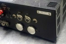
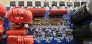
Hi all, I have a Punch 40 DSM on the bench
Which powered up but no audio, there was evidence
of cap leakage around the 10uf 16v smd caps.

So I replaced the lot including the ones on the upright board.

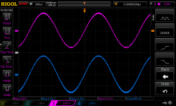
The amp plays nice and clean on the right channel but low on the left channel. It also plays audio via the left channel when only the right channel input is connected?

I've gone through all the new caps and checked for bad connections and they're all good.

There's no signs of overheating or excessive current draw, any ideas on troubleshooting this one appreciated thanks

FS: SpeakerPower SP1-300-HT subwoofer plate amplifier 300 watts

Selling a lightly used Speakerpower SP1-300-HT amp. No filters or boost built into this one. I purchased it from new from Madisound in March of last year to power a Clark synthesis Platinum tactile transducer. Problem was Parts Express listed the power handling of the transducer incorrectly... The Speakerpower amp destroyed the transducer. Decided to go a different route and no longer need this amp. Works perfectly.

details here: Specifications - SpeakerPower

Currently new goes for $419

also a short forum post regarding the home theater I build where the amp was briefly in service: caveman cinema - AVS Forum | Home Theater Discussions And Reviews

also listed on Ebay - my name there is ryan3.14

don't hesitate to ask questions
be well
Ryan

$275, now $250 - I'll cover PP and shipping within the CONUS

Manley panel lights hack

Do you have a Manley phono preamp, preamplifier, integrated amplifier, or power amplifier? Are you annoyed with front panel lights that are as bright as the sun? Just kidding, only as bright as the Las Vegas Strip at midnight. I'm talking about the front panel Manley logo and power button that are at least ten times as bright as the panel lights on any other piece of electronic gear I own.


This is how I fixed it. For the Manley logo window, I cut to size two pieces of white printer paper and slid them into the tiny space between the logo plastic and the case sheet metal. For the power button, I used an appropriate size hole punch to make a round dot out of black electrical tape, and stuck that in the middle of the button. There was still a lot of light emanating from the top of the case through the vent holes. This one is just a little harder. The case cover has to be unscrewed and removed. I found a junk piece of black plastic and cut it to carefully fit it over the light bulbs so that it would not disturb anything but still stay in place.


Problem solved. Nothing does any permanent damage, and can easily be removed. This is the after photo. Sorry I didn't take a before photo for comparison. But trust me, now the intensity is much better and matches my other components.

Attachments

  • Chinook light.jpg
    Chinook light.jpg
    387.2 KB · Views: 105

Car coax driver in sealed box

Hi everyone !

Working on a project with strict specs, I was wondering if the use of car coax speakers could be the solution.

Having a small enclosure to use, full range speakers never go low enough in a sealed design. I don't really have room for a 2-way configuration, so coax would be a good way to go to get the "full-range" and still go low enough.

I understood that car speaker are meant for infinite baffle configuration, but what would be the effect on a 50Hz rated car speaker in a sealed box ? Would I just loose a small portion of the frequency response, or would it be a complete disaster ? I can't get any T/S parameters for any of those I'm interested in

And also, would a open baffle configuration be better ?

Thanks for your help

Peavey CS800x - DDT light, low output, distorted

I use this amp to power two 12" subs in my home audio system.
Overkill? Yes.
Was it cheap? Yes.

It had been working without issue for months. Issue showed up this week.

I have swapped speakers and line ins, issue remains on channel B.
I have worked the Bridge/Stereo and DDT switches multiple times, issue remains.

Basically, the DDT light comes on at the drop of a hat. For example, this is what I went through yesterday:

1. I power on with nothing plugged in (speakers or source) nothing aside from the power lights are lit.
2. Connect anything to the input while powered on, just connecting a 1/4" jack that is not connected to a device at other end, ddt light comes on and stays on until I power cycle the amp.
~ But sometimes I can connect a wire and it does not engage DDT; maybe 10-15% of the time it does not engage. ~
3. If I connect wire and DDT does not engage, I will connect other end of wire to my powered off function generator, DDT light comes on. Will stay on until I power cycle the amp.
4. Powered off function generator connected to the input of the amp, I power on amp - no DDT light. If I unplug the wire from the powered off function generator, the DDT light comes on and stays on until I power cycle the amp.
~ Sometimes I can unplug and DDT light comes on for a few seconds then shuts off. If I then plug that wire back in, DDT light comes on and stays on until I power cycle the amp.~

I have not swapped the driver boards from A to B but imagine the issue will follow.

B+/B- are fine.
26v supply measure 24.33v

Riedon UB5C!!!

Let me tell you a story. I bought these because they were "pulse" rated. Wow!
After hearing a bad oscillation go through the system (it sounded like a Degauss going off over and over), I could smell a burning...

This resistor passed many times it's rated power repeatedly, smoked, cracked in several places, but still tests to 10R and works!!! I replaced it of course, but if you want a reliable resistor these are just excellent!

UB5C-10RF1

FS: Philips BD230 & BD231 grey ( Genuine, NOS)

Today I found a large amount of Philips BD230 & BD231 in a box while cleaning up, I no longer have any use for the transistors and offer them here for sale. I have 8 Tubes each 50piece BD230 / BD231 Philips. The BD's are the original gray-plastic parts. Can replaced BD139 and BD140. Bought them from Spoerle Electronic in 1996.Offers are welcome. Shipping by DHL registered mail from Germany. PayPal is accepted buyers needs to pay the additional PayPal fees from 4%. Shipping prices are different depends on the country.

Regards,
Walter

Attachments

  • IMG_20210310_131058.jpg
    IMG_20210310_131058.jpg
    153.4 KB · Views: 97
  • IMG_20210310_131109.jpg
    IMG_20210310_131109.jpg
    429.2 KB · Views: 99
  • IMG_20210310_131115.jpg
    IMG_20210310_131115.jpg
    282.6 KB · Views: 103
  • IMG_20210310_131119.jpg
    IMG_20210310_131119.jpg
    292.8 KB · Views: 100
  • IMG_20210310_131124.jpg
    IMG_20210310_131124.jpg
    424.8 KB · Views: 92

MiniDSP alternative

Hi
I'm playing around with an active speaker using JBL 2226h and B&C DC250.
I'm using a MiniDSP 2x4 for crossover and DSP.

The problem is there is a hissing noice which I can't live with.
I tried a lot of different things but I can't get rid of it.
I have googled this and there seems to be a with the Minidsp regarding this maybe because the drivers are very efficient?

So, what to do?

I would have upgraded to the 2x4HD but if this also has the hiss, then that would just be waste of money.
I tried to find an alternative to Minidsp but nothing really came up - is it true that there isn't any other products like Minidsp on the marked?

I don't want to go for a PC based DSP.

I have also taken a look at Hypex FA123.
But how good is the DSP here compared with the MiniDSP?
And, what about sound quality do they sound good?

So what are my options?

samsung lcd tv glass removal.

Hi There


I have a question about a tv from samsung a big type 30+ inch.

The tv has a mist on the edges and i did see when look from above that it is from the glass protection plate and not the lcd itselfs, these letters from a subtitled movie was oke, I did see reflection of these letters on the glass and cause a unclear mist like look. It seems that or the glass is damaged by the user or it is contaminated on the back side, where I need to open it to clean.

Do someone now that this glas plate is removable and be cleaned?, or is this a panel who can not be dissasembled.


thanks.

kees

shaped burst

Hi guys,

I have been looking for a signal/function generator that could output a shaped tone burst as in the attachment.
Surprisingly, although almost all have a tone burst capability, I have not found a single one that could window or filter the burst. Many have window functions like Hanning or Bartlett, but apparently only as a wave shape to output, not to filter a generated signal.

Am I looking for unobtanium? (I know you can generate such signals offline with for instance a spreadsheet, and upload to the test equipment, but I specifically wanted a native hardware capability).

Grateful for any pointers!

Jan

Attachments

  • cosine burst.PNG
    cosine burst.PNG
    30.9 KB · Views: 246

Irs2092 dead ? Missed wiring

Hello, i bought a pair of irs2092 i powered the one but i messsed the wiring and i just saw a movement of the speaker like whene you plug a jack nothing esle i tryed many and my fuse were burning on my supply i replaced until i put in direct ans my transformer were acting like chortcuted so i stopped and checked once more my wiring until i noticed i messed with the + and - of my rectifier ... I was for sure it was wrong, i then tell ok well dead for dead i put the good wire and i got the xlsemi xl7005a who got burner apparently nothink else
I need somes peopple to tell me if i could repair it by only replacing the xlsemi xl75005a or it probably killed somethink else ?

190704120002211648.jpg


Thank you

B&W802D Speaker A vs. B: Low Frequency Response Differences

Hi:

In my process of conducting digital room correction for my audio room for my B&W 802D speakers. I noticed that one speaker has an approx 6dB lower in peak at around 40Hz, and the roll off is very different. I swapped the speakers in position, and the similar characteristics followed with the weaker speaker to the other position. These speakers are about 15 years old. I checked the crossover on both speakers, and visually nothing seems to be wrong i.e. capacitor physical shape not distorted. I have attached the amplitude responses with weaker speaker in right, and left position. Also, a picture of the crossover.
Any ideas on why the weaker speaker at low frequency is behaving like this?

Regards,

RF Phil

Attachments

  • Weak Speaker on Left.JPG
    Weak Speaker on Left.JPG
    71.7 KB · Views: 207
  • Weak Speaker on Right.JPG
    Weak Speaker on Right.JPG
    71 KB · Views: 204
  • B&W802D Crossover.jpg
    B&W802D Crossover.jpg
    982.7 KB · Views: 195

Morel TSCM 634 woofer/midrange thoughts?

Came across this driver and it looks interesting on paper. Appears to have a nice flat mid band and reasonable efficiency, plus decent power handling. Contemplating on using this as a midrange in a large 3 way.

Anyone have experience with this driver.

Looking for some distortion measurements as well.

Attachments

  • Screenshot_20210306-040123_Chrome.jpg
    Screenshot_20210306-040123_Chrome.jpg
    639.1 KB · Views: 279

Nakamichi MB-100 (You can guess where this is going!!!)

So, I have a lovely Nak MB-100, with the obligatory 'e mecha' error. The unit has been stored for about 6 years unused, I don't recall it having the error then, but I also though the illumination was green, and this one's amber (easily confused). Upon lifting the lid I see Base Systems (uk repair shop) have been in here in 2001 on behalf of BBG (I assume they were the Nakamichi UK distributor).

The unit behaves fine until you select a cd then you get the error.

The magnetic puck was stuck to the spindle, I've clipped it back on the holder.

CN107 has been fluxed up and resoldered

Other than that it looks very clean in there. The unit makes no attempt to load a cd or move any of the mechanism. The cd slot is blocked by the little tabs.

Any suggestions on where to start next?

  • Locked
Semi isolated AC lines, and a ground question

I'm running a separate Romex line from my outside AC power source, straight to my monoblock amplifiers. I plan on bypassing my breaker box, and using in line Breakers. This should give me as clean a signal as I can get, without dedicated power poles outside. My monoblocks sit right against the outside edges of my side walls. I plan on driving a ground rod outside the wall by the amplifier, and using bare copper ground cable to completely isolate the ground from the rest of my system or house grounds. My question is, is one ground rod okay with using both grounds from each amplifier to it? Or would I be better off driving and ground rod outside each amplifier, a grounding them separately? Thank you

Klipsch Forte IV ... Why no DIY ?

Seems like the Forte IV is the newest flavor of the month speakers in the media at least.
Klipsch has been the strangest speakers since I've been into audio stuff...circa 1982. Meaning, while they have always had flaws in sound reproduction, they have also always had a sound that draws a lot of people in. I remember in about 1986 or 87, everytime I'd go into our local Luxman, Yamaha, Klipsch, Polk dealer, they would have background music playing on either Fortes, or Chorus II speakers.... and you would not want to leave for some reason. Flawed sound and all. There seems to be something going on that appeals to many. So I'm just wondering, this being so, why hasn't someone taken the Forte 4 for example, and engineered it "properly", so it maintains the part people like so much, while addressing the obvious flaws all reviewers point out? Is it simply not possible to get a horn setup like the Forte to sound as good as conventional speaker designs?

Tweaking an ESI Juli@ XTe card

Howdy

With a lot of help and guidance from "Greg from Mississippi" I've begun exploring the digital section of my ESI Juli@ XTe card (PICe version) with a view to (1) soldering a direct connection to an RCA jack for S/PDIF Out (done), (2) powering the card independently of the motherboard, (3) upgrading the clocks and (4) possible other upgrades. I'm wondering if anyone here has modified the digital side of the XTe version of this card.

I've done quite a lot of work tracing most of the key parts and voltages on this card. In many ways it is similar to the older PCI card but in others it's different. The card draws both 12V and 3.3V from the motherboard. -12V is produced on the digital section of the card but appears to only be used on the analogue part of the card. In addition, 5V (DVCC) is generated from the 12V (UA9). It too is passed to the analogue portion of the card. Annoyingly, the 5V appears to be used by UA7 on side A of the digital part of the card (and also for the optical out which I care less about). Were it not for this, I'd probably try disconnecting the 12V completely. Lastly, 1.8V is generated from the 3.3V (UA8).

Here's a couple of pics of the card with my notations. Directly beneath each is a download link to a high-resolution version of the same image. The last link is a high-resolution version of side A of the card which shows the traces more clearly.

Side B

An externally hosted image should be here but it was not working when we last tested it.


High-res image

Side A

An externally hosted image should be here but it was not working when we last tested it.


High-res image

Side A traces

For the clock upgrade, I am likely going to use one of Fidelity Audio's micro clocks

Fidelity Audio : C3 Low Jitter Premium clock Micro clock 2 dual output for squeezeboxes

The pictures above mark the capacitors and resistors which need to be removed along with each oscillator (Y1 and Y2). Each of the oscillators has an output voltage of 1.4V (although on one end of my Y1 oscillator was measuring 1.3V).

I've also marked the points on side B of the card for direct wiring for S/PDIF out in order to avoid the breakout cable.

I suspect the best entry points for direct power is intervention via the riser cable.

Anyone else looked at this card in detail? I'm a novice and would appreciate any pointers!

Regards

Steve

Help a noob? Is crossover impedance on XSim accurate?

Hi there,
Sorry if this is a repeat thread, I had a look and couldn't find an answer.


First time using Xsim to model some crossovers, my SPL is getting there but my Impedance graph is wild, way off what it was before I added any components.
Is this because I'm using stupid value components? Or wiring it incorrectly? An issue with Xsim or my data values? Or is just something I don't need to worry about?
Please could someone take a look at these screenshots and tell me what I'm doing wrong? Crossovers are doing my head in.

:smash:
:scratch2:
Any advise is greatly appreciated


Woofer: Dayton Audio DC160-8 6-1/2" Classic Woofer


Tweeter: Dayton Audio DC28F-8 1-1/8" Silk Dome Tweeter


Kind regards, Luke.

Attachments

  • with.png
    with.png
    88.4 KB · Views: 251
  • without.png
    without.png
    89.3 KB · Views: 242
  • With.jpg
    With.jpg
    58.6 KB · Views: 229
  • Without.jpg
    Without.jpg
    138.5 KB · Views: 246

Powerhandling in the real world - driver & enclosure

Hello follow DIY'ers

I was pondering the various ways a driver can fail depending on real world operating conditions, meaning input power, bandwidth and enclosure design (loading) and how this may differ from what is specified for the driver itself depending on method used.

Thermal failure is input power related but the time it takes for this failure to occur will also be influenced by ambient temperature and driver ventilation aspects as granted by the enclosure and driver excursion profile.

Mechanical failure could mean several things depending on how the driver is designed, and as before time is a factor here as well since there are different thermal masses that makes up a driver mechanically, the metal and ceramic parts of the motor structure will take a bit longer to reach critical temperatures compared to the voice coil (for example).

So how does one arrive at what the power rating is for a certain driver in a specific design? Testing and measuring is a given, but this may not be an option for most DIY'ers since it requires specific equipment, climate chambers etc.

The reason I ask is that I believe that matching an amplifier to the driver specifications without taking the enclosure into consideration (which seems to be a fairly common practice) could be risky, or am I wrong about all this?

Reproduce EQ circuit

I have a reproduce EQ circuit here that I cannot figure out. Here's a .pdf of the Otari's service manual screen shot and the circuit I put into LT Spice. It is supposed to give an adjustable high frequency equalization; but in fact LT Spice says it just gives a HUGE low frequency boost. I have shown the circuit in LT Spice as it would occur in High Speed, with Q107 turned on and Q106 and Q108 off. What am I missing?

Attachments

Orion 2150GX trouble powering up

Maybe its cause this old girl isn't using a TL49x or SG352x. Seems to be a self-oscillating supply. I was able to get it powered up a few times at first on my small 5A power supply, but it took about 45 seconds to "charge up" and then it idled at about 1.5A. I played and tested with it for about 20 minutes, power cycling it a bunch of times... But now nothing. I then tried it through a 10A fuse to a large battery and it instantly popped the fuse.

I pulled a few of the rail caps and tested them. They seem to spec OK on the Fluke 16. The rects seem to be OK as well.

What am I doing wrong here? None of the transistors are shorted and I was actually able to get some audio down both channels, bit dirty; the first couple times it powered up. I believe I found a bad 10uF cap on the right channel, replaced; but now I cant get this amp to cooperate very well.

Hammond Transformer Dimensions. Damn!

I recently purchased a Hammond power transformer that met my needs electronically, and dimensionally, as it had to fit an existing chassis. I went from the Hammond PDF file with its dimensions for the mounting bolt holes. However, when it arrived, and I checked, there was no possible way it would fit my chassis as the mounting bolt dimensions were dramatically larger. (Seriously, there's not a snowball's chance in hell this thing will fit!)
Moral of the story, if you're trying to fit a Hammond transformer to an existing chassis, don't trust their measurements.

Help.

G'day to all out there from Australia. I'm new to this Forum and would like some help and advise.
My hobby is woodworking and I have always wanted to build a portable Bluetooth Speaker using quality products for good sound. The cabinet is no problem however, the components to use is, ect: what speakers to use and how many, and all the other stuff I will need? If anyone out there can help and advise it would be very much appreciated.
Cheers
Ronniedog

Equipment for studio recording large ensembles

Hello diyAudio Community,

I see a lot of posts for bettering a listening experience. I'm curious if you'd lend your expertise in beefing up a studio for world music sessions (like for Sufi music). Primary listening difference maybe that there are hardly any of the low low frequencies.

For now, working with Universal Apollo and Adam Audio A7X. What would be the next major upgrades (especially to build from scratch)?

Icepower asx50btl, and asx125btl questions

I am currently running balanced xlrs out from my xilica xp4080 crossover to my asx50btl, and asx125btl amp modules (6 modules to the amp). I am going to be selling my Xilica and replacing it with a MiniDSP ddrc88a for crossover and Dirac

Questions:
1: If I run rcas out of the minidsp and into my 6 channel icepower amp...can I just rewire my xlrs on the amp for rca wiring (non balanced hookup)?
2: If so will my modules still run in bridged btl mode? If not is there a way to be able to get the power of bridged without a balanced source?

If this works...can I connect up 2 asx125btl amps to 2 different woofers from the same XLR, or do I need to use 2 XLRs and do the split in the crossover? I would like to do this because I have 2 woofers in each cabinet and they are each 4 ohms, but when driven off the same amp they are 8 ohms. I am thinking if I could drive each woofer with its own amp I could get more power to each woofer.

Does this make sense? Is there a downside to doing it this way?

Instant-off relay timer for muting line outputs

Hey y'all, here's my take on an instant-off relay timer, used to mute line level inputs and outputs, either by shorting or switching the signal. (In most cases, shorting the signal is preferred.)

Instant-Off-Relay-Timer.png


It will run off a wide range of supply voltage, from 12-24VAC, from which it derives a regulated 12V for the timer and relay.

Loss-of-AC detection circuit pulses Q1 into RC network R3/C3, to bring RESET voltage above 1.8V in normal operation. If more than one cycle is lost, the timer resets and cuts power to the relay in less than 10ms.

The CMOS versions of the 555 timer, the ICM7555 or TLC555, have an actually useful RESET line that sources in the pico-amp range, so allows for high-impedance control. The bipolar NE555 has to be pulled down much harder, so most designers chose another method to reset it. More on this topic here.

I'm specifying very high-impedance control circuitry to avoid electrolytic timing capacitors, or large polys.

Here's the SPICE.
Instant-Off Relay Timer

And you'll need this model and assembly file for LTSPICE. Verify the spice install file path in the ASY file.
ICM7555 Model and ASY

It's not been tested physically yet, just in LTSpice. I will be bread-boarding it soon.

See any issues?

If it's good, I already have a board design done in Eagle, and I'd be happy to share that as "Don't care-ware".

Is my approach to a passive crossover design OK?

Hi all,

I want to simplify my current setup by switching from an active crossover (MiniDSP) to passive one, on my Four Pi speaker clones. My speakers are essentially the same design, with a different port and tuning.

I have access to a calibrated mic, calibrated soundcard and REW, as well as DATS, and so forth.

This is what I am thinking - with measurements taken outside, on the ground, with no close walls / reflections:

Measure the impedance sweep of the tweeter
Measure the impedance sweep of the woofer (mounted normally in the enclosure, so the port is included)
Measure on-axis response of the tweeter at 1 meter / 2.83V RMS
Measure on-axis response of the woofer at 1 meter / 2.83V RMS
Repeat 3 and 4, but off axis (30, 45, 60 degrees)
Use software such as XMachina to import the impedance and frequency responses, and model 2-way crossover from there
If desired, use a DSP to put in the values of the passive crossover, to see what the response looks like
Iterate 6-7 until happy with response/sound
Purchase components
Assemble, test
Joy

Woofer: 15" JBL 2226H, PDF

Tweeter: 1" B&C DE250-8, with the H290C horn/waveguide. Also a 50W LPAD to attenuate the tweeter, which I might, or might not use, with the passive crossover.

Questions:

Is this a sensible approach, or am I missing something?
Should I measure the frequency response (in addition to 2.83V) higher voltage levels to get an understanding of the driver charateristics closer to the actual listening levels?

Many thanks in advance

Bonus, a few pictures (attached)

Attachments

  • JBL.JPG
    JBL.JPG
    383.8 KB · Views: 87
  • JBL2.JPG
    JBL2.JPG
    107.2 KB · Views: 83
  • JBL3.JPG
    JBL3.JPG
    217.5 KB · Views: 87
  • JBL4.JPG
    JBL4.JPG
    277.8 KB · Views: 85
  • JBL5.JPG
    JBL5.JPG
    174.9 KB · Views: 84

Discrete Sigma/Delta DAC

For purely educational reasons (for now), I'm interested in building a discrete Sigma/Delta DAC. I'm not interested in anything high quality/audiophile or in something cheap, I would just like to understand how they behave in practice and play around with them. But, it seems nobody else is interested in this as I can't even find schematics of thought experiments and there are definitely no kits either...

I can't imagine that nobody else is interested in such an experiment. Is it perhaps too hard to handle the high frequencies in a controlled way on a breadboard/DIY PCB? Are the distances between DIY-able components simply too large?

Best current KT88? Plus TSE-II build & “Engineer” Solder Sucker

First, best wishes to George.

Look like it’s open season on 67 year-olds; I “popped a gut-string” about 2 mos ago (building a little bungalow on the Texas Coast, doin’ SUMTHIN I shouldn’ta been doing). Direct Inguinal Hernia. Surgery 3 weeks ago, still kinda whupped... this sure is No Country for Old Men...

Question: what’s the best current production BUDGET KT-88?
“Budget” meaning no more than about $50/ tube...Genelex Gold Lions look good, but is there something better?

I just realized that I set-up my shop amp for higher voltage (450-500vP) w/NOS Thordarson PST (about 820v at 200mA) and large swinging choke. To get low 400 vP, I have to use a 16uF choke input, so there’s plenty of EMF in reserve; figure I might as well use it. Only limitation is the G-series 5K EDCOR OPTs, but those can be upgraded if “required”.

In other news, got a pair of TSE-II boards from George today.
One is going in a 45 amp with 5K Transcendars from stock. Last night, I slapped some scraps of ash veneer on an old Baltic birch chassis. So far so good; now WOM (waiting on Mouser).

In still MORE news, got one of those “Engineer” plunger type solder suckers, cause I have 5 or 6 circuits that need dissection. Was gonna spring for a vacuum pump type, maybe even a Hakko to match the soldering station; that would have been a mistake. The “Engineer” solder sucker “works a treat” as my Limey buddies say. Gets about 80% average on first shot. No more screwing around trying to get solder wick to wet-out. Highly recommended.

Attachments

  • 4B7AB87C-88B2-4E23-B31D-1EF8974EAD84.jpeg
    4B7AB87C-88B2-4E23-B31D-1EF8974EAD84.jpeg
    304.9 KB · Views: 102
  • 750DEC5A-10D2-40F0-BA66-F5B7C479DD29.jpeg
    750DEC5A-10D2-40F0-BA66-F5B7C479DD29.jpeg
    253.5 KB · Views: 103
  • 8E3179C7-1D30-4CBB-B165-30E84A9BA710.jpeg
    8E3179C7-1D30-4CBB-B165-30E84A9BA710.jpeg
    308.4 KB · Views: 95
  • 8F87A409-8DAC-4B9E-AE9A-7A70233C8531.jpeg
    8F87A409-8DAC-4B9E-AE9A-7A70233C8531.jpeg
    505.7 KB · Views: 101

6J43P, single stage, transformer coupled, push pull, 3w amp.

Hi everyone, I haven’t posted any of my previous projects here but I thought better late than never.

This amp is 3w stereo design for sensitive speakers.

It’s intentionally super simple. It uses a interesting Russian signal pentode with a dual plate design. There seem to be a lot of these available at reasonable prices.

It’s cool because it’s got fairly high gain and transconductance when triode strapped. The gain is high enough to be driven to clipping with less than 8v p-p.

I also had a really nice pair of vintage 1:5 600:15k Ampex transformers I wanted to use in a project.

The PS is regulated 230v and 6.3v.

The outputs are a AliExpress purchase and are the weak link. Though they perform fine at 3w.

Distortion isn’t exactly low and depends on if you can find a well matched pair of tubes. .5-1% at 1w rising to 3% at visible clipping at 3w.

The power transformer I used is a old Triad organ pull. I’d change this if I could do it again. It has a slight buzz and coupled to the output transformers even though they orientation is correct for lowest hum. This basically undoes all my work regulating everything and my s:n is back to 75-80db vs 1w. Oh well. The toroids I normally use have way less issues coupling to outputs.

The excellent box is made of bamboo and my friend Sean used his CNC to create it.

Attachments

  • 75D0A876-E59B-4DBA-AD0B-61FE06FF0EE7.jpg
    75D0A876-E59B-4DBA-AD0B-61FE06FF0EE7.jpg
    492.8 KB · Views: 428
  • C3C644FB-807C-456D-A025-C9EBD15714EC.jpg
    C3C644FB-807C-456D-A025-C9EBD15714EC.jpg
    562.8 KB · Views: 374
  • B0E60E95-DDF5-4C3B-80EC-A0C35BBB5680.jpg
    B0E60E95-DDF5-4C3B-80EC-A0C35BBB5680.jpg
    527.2 KB · Views: 360
  • AF67993F-E571-4D9D-9EE8-A624273D4524.jpg
    AF67993F-E571-4D9D-9EE8-A624273D4524.jpg
    670.1 KB · Views: 399
  • B0A3AFC1-A8C8-45DC-A8AB-1C9324482CBC.jpeg
    B0A3AFC1-A8C8-45DC-A8AB-1C9324482CBC.jpeg
    60.1 KB · Views: 507

Onkyo A-9555 Amplifier Protection

Hi guys!

This time got Onkyo A-9555 amplifier for repair.

Amplifier is in Protection mode - Standby LED is blinking. And Reset doesn't help as in many cases desbribed here on the internet.
So long story short:
  1. Of course, started by measuring all the voltages and checking components for visual defects.
    Found Zener short to GND. Replaced both of them. Please refer to the schematic below.
    Onkyo1 — imgbb.com
    These two signals belong to SPRDET and SPLDET circuitry which responsible for protection and/or speaker/voltage detection at the output.
    Now the voltages are good at the nodes. Previously one was pulled-down to GND by the short Zener.
  2. Found that R645 is burned [for which Zener was blown]. Placed a jumper instead.
    Onkyo2 — imgbb.com
  3. Amplifier is still in Protection mode. Tried to disconnect power plugs P503 and P504. Vuola, without -57V amplifier starts and works properly (of course without PA part).
    Onkyo3 — imgbb.com
  4. Checked what's wrong with this -57V rail. So whenever amplifier is starting up and checking the voltage at the ouput this -57V comes into play and is present at the both outputs. So the protection works and the amp goes into Protection mode.
    Onkyo4 — imgbb.com
  5. Checked mostly of active and passive components in PA with continuity [diode] function and they are all seem to be good - their values in proper range for diodes, transistors, etc. Power mosfets in half bridge seem to be good too. Haven't checked with component tester though as it is hard to pull them out of the PCB.
Maybe some new ideas to try and check.
Thanks in advance.

P.s. Full schematics in .pdf here:
WeTransfer

Mc2 Mc450 help

I’m lookin for a bit of help with an Mc2 Mc450 amplifier that won’t power up.
It was working fine until I cleaned it inside with a can of compressed air.
Now it won’t power up, no lights or anything. The fuses are ok and power is reaching the circuit board.

I’ve very little electronics knowledge, so would appreciate if anyone can point me in the right direction. I have the schematic, but don’t really know how to test if each component is ok.

Thanks
Matt

Is this a good circuit for general listening

Greetings,


i am not very skilled and i dont know alot about tube amp design,
im more into solid state. A friend of mine has an old chassis,

and on there he has 2x ECC83 an one 12AX7 and a sutible power transformer,
for filaments and the amp itself and a rectifier with smoothing caps and

a smoothing coil. There is also an output transformer with a centre tap on primary and on the secondary a speaker is connected.


Only trouble is, that there is no circuit 🙂
So he asked me if i could make a very simple low power amp.

So i looked on the net a bit and found a circuit and brief explanation in the link below. I would like to build a circuit #2, because its simple and i have almost all the parts.


So i ask you experts, is this circuit (#2 in the link) okay for general not very hifi listening?
And are there any errors?


EL84 Valve Amplifiers

NAD-3225PE DC offset issue

I wonder if any of you kind folks might be able to help me debug a DC offset problem with a NAD 3225PE?

It belongs to a friend, and one day it issued forth magic smoke. The output stage on one channel had failed catastrophically - some passive components badly charred, and dead shorts on the 2N3055 and MJ2955 output transistors.

I replaced all the transistors in the stage, together with the damaged passive components. I also replaced the 2N3055 and MJ2955 in the other channel to keep them matching. And I did a recap of the whole thing while I was in there.

It's almost all working again now, but with one problem. I've got a ~1.9V DC offset on the original blown channel. I can adjust the idling current (on both channels) just fine, and I have ~1.5mV DC offset on the good channel.

I've attached the schematic, plus a closeup of the output stage, and the alignment instructions. I've circled R444 (idling current adjust) and R412 (DC offset adjust) in red. I've also marked R456 (the checking point for idling current adjust). Point "Y" is the signal from the pre-amp out. No matter what I do with R412, I can only get the DC offset down to ~1.9V - if I short R416 next to it, it drops to ~1.7V.

I'd be very grateful if anyone can point me in the right direction.

Attachments

  • nad1.jpg
    nad1.jpg
    531.7 KB · Views: 127
  • nad2.jpg
    nad2.jpg
    277.8 KB · Views: 112
  • nad3.jpg
    nad3.jpg
    100.1 KB · Views: 134

The best phono preamp on op-amps?

Hi there! I'm new to these forums so maybe this question has been asked many times. I tried to search, but couldn't find the exact answer... I've been reading threads about phono preamps but still wandering which one is the best...

I don't care about the price of parts. I'm looking for a high quality preamp schematics. Which one of all phono preamps projects mentioned on this forum is the best in terms of sound quality, very low distortion and low noise for MM pickups?

The reason I'm asking this is because I'm planning to build an amp with line and phono inputs, and also be able to use the phono preamps that I'll include in this amplifier as a stand alone devices for recording....

Thanks. 😀

NAD 3130 blowing fuses

hi im hoping you guys out there can help
The amp i am working on at the moment, a NAD 3130 is blowing the fuses on the 24v part of the amp (f3 and f4) directly after the impedence switch.The other tappings ,29v circuit blowing fuses.
so this is what i have done so far.The transformer with the fuses out is giving 24v on both supplies.I have removed and tested all the main output transistors and diodes, these seem fine ,i havent tested the caps.the only thing im left with is thinking the transformer is faulty as when i disconnected one side of the impedence switch one side of the circuit,it didnt blow a fuse, so could it be the transformer? i dont know how to test these so some help would be great.If the transformer was faulty would it still give off the correct voltage?


many thanks


paul

Attachments

  • 3130 fuses.jpg
    3130 fuses.jpg
    146.1 KB · Views: 165

Hospital / industrial grade AC isolation transformers?

Apparently using a hospital / industrial grade isolation transformer is considered by many to be the best *cost effective* device for your AC. For those in the know, what brand, specs, etc. are recommended?

I saw a big thread somewhere not long ago but I could never figure out what to buy

I don't know which forum to post this in so I figured this was probably the best

Marantz CD94 opamp

Hi all,

I scored a Marantz CD94 from UK and seems to be a non modded unit. Still has the old capacitors intact with no leak and performs well. I am thinking if upgrading opamp to OPA626AU would give a significant improvement. The reason I ask if the op amps for 4 is around 100 dollars. I also have Burson V6 but only 3 (took it for Xonar Essense audio card) so what option would you go. OPA627 or buy one more burson v6 and go all out? Thank in advance

TLV9152

Hi all,

I've been on the hunt for a good RRIO opamp for battery-powered applications, and the TLV9152 is looking quite good from the spec sheet:
https://www.ti.com/product/TLV9152

  • low offset/drift (typ.125uV, 0.3uV/C)
  • low distortion (0.00021%)
  • low noise (11nV/rt.Hz @ 1kHz
  • low power (c.500uA/amp)
  • reasonable cost ($0.354/1k)
I didn't find any mention of it here so far, just wondered if anyone was already using it, or avoided it?!

Thanks,
Neil

Arcam A60 channel inbalance

I've got an Arcam A60 pulled from the bottom of a large pile of bought for a rainy day amps with a channel imbalance which increases with volume.

I've attached some scope screen shots to illustrate this please note the scopes voltage reading.

The amp has been recapped, no problems with this.

I have discounted the scope as it reads out on my meter as well and volume control as I have a spare alps blue that I've put in and it still reads the same, where to look next?

Attachments

  • DS1Z_QuickPrint4.png
    DS1Z_QuickPrint4.png
    43.7 KB · Views: 98
  • DS1Z_QuickPrint5.png
    DS1Z_QuickPrint5.png
    43.3 KB · Views: 101
  • DS1Z_QuickPrint6.png
    DS1Z_QuickPrint6.png
    39.2 KB · Views: 102
  • DS1Z_QuickPrint7.png
    DS1Z_QuickPrint7.png
    44.5 KB · Views: 106

  • Poll Poll
Optical and Coax cable length?

Is 1M (3.3Feet) of Coax or Toslink digital cable the right length?

  • No! Too long! 0.5M (1.6ft) is good enough!

    Votes: 2 13.3%
  • Yes, perfection!

    Votes: 6 40.0%
  • No! Too short! 1.5M (4.9ft) is much better!

    Votes: 3 20.0%
  • No! Too short! 2.0M (6.6ft) is much better!

    Votes: 0 0.0%
  • No! Too short! 3.0M (9.9ft) is much better!

    Votes: 0 0.0%
  • No! And you don't have the proper length in the poll! (please state length below)

    Votes: 4 26.7%

Do you feel that 1M of optical or coax digital cable is not long enough? Or is it too long already??? Please let me know and we will see about getting the cable with the "right" length in stock.

If you are interested in Analog Interconnects, you can also post and respond to the poll here too. 🙂

Pricing Help Needed (please)

Hey all,
I could use some input from you guys. I have been asked to build a few amp conversions in tolex covered head cabinets. I need some opinions from other players about how much these would be worth to players to decide if it's worth doing. How much should I charge for these amps?
Thanks Guys for any input you can share.

Info on the amps is:

[font=Tahoma, Verdana, Arial, sans-serif]
Custom tube guitar amp. - YouTube

This amp was designed and constructed using the basic foundation of a 1960s (Akai M8) Roberts 770X tube reel to reel tape recorder. The amplifier circuitry has been optimized to specifically serve as a guitar amp rather than as hi-fi equipment. Where practical the original vintage components, including the tubes, have been kept.

There are 2 instruments inputs which share the common volume and tone controls. The 2 inputs however employ separate, and different, input stage tubes and therefore sound very different. The first input uses an EF86 (6267) tube. These tubes were used in 1960s vintage VOX amps, and are still used in some Dr. Z, Matchless, and other boutique amplifiers. The 2nd input uses a 12AX7 (12AD7) tube. 12AX7s are the most common preamp tubes used in guitar amplifiers such as Fender, Mesa Boogie, and Marshall. All of the tubes are the original vintage 1960s tubes. This amp is very quiet (background noise and hum) and breaks up nicely at reasonable volume levels.

The tone circuit uses a modified passive Baxandall/James circuit (Bass and Treble controls) similar to the type of tone stacks used in the original Ampeg, Orange, and some Dr. Z amps. Additionally, a boost switch increases the gain and frequency response of the amp providing additional tonal flexibility.

The output stage is a single-ended class A power amp. This amp uses an EL84 (6BQ5). Single-ended class A amps were used in many lower power 1950s-60s Fender Tweed and Blackface amps and in Vox's AC-4, which also used the EL84 tube. The amp uses a 6X4 tube rectifier. This amp works great for rehearsal, small venue use, and especially studio recording.[/font]

Dropbox - Error ... 5.jpg?dl=0

question about multiple transformer wiring on primary side

I have some harvested amp boards and transformers that I would like to make use of. The transformers have a single 120VAC primary and multiple secondaries that are used to power multiple amp modules. All these parts were obtained from a multi-channel Crestron CNAMPX-16x60 power amp.

The question I have is how I might be able to use (or not) the same transformers on 220/230VAC mains (European standard). If I will be using two of these transformers, can I simply connect their primaries in series so that each one sees half the AC mains voltage? If I do that, can I leave some secondaries "unused" on one or both transformers?

Rotel RA-810A Behavior

I am in the process of restoring my Rotel RA-810A that is sounding very concise & balanced, really like it. The following small problems are found:\

1) When selecting Phono there is a significant hiss-interference sound coming from the output, when turning the volume past noon, gets louder. With the cover removed passing your hand near the components of the preamplifier stage I noticed the interference getting worse.

2) Some cross-talk between inputs.
3) Excessive thump on speakers upon turning-on and off.
I can fix this by adding a delay module+DC protection.
4) The voltages on the schematics are near 4-6 volts lower than the ones measures on the board.
5) Strangely the model RA-920AX, almost identical specs, has voltages closer to the ones found on my amplifier.

Any suggestion would be appreciated........thanks

Attachments

Recommendations for High Quality Audio Low Power Dual Opamps

I’ve been using this circuit for years now (attached below), Overall, I’m really pleased with it, but I’ve recently learned that I can most likely swap the opamp to have the same audio quality but have my 9v battery last longer.

Quality is key for me though, I’m running clean guitar through this, and with as wide performance dynamics as can be gotten from a guitar (ie from very quiet passages to hard, percussive strumming). I’m happy with the sound of the circuit though, so if I can’t find another opamp of at least equal quality to the OPA2134, I’ll just keep spending the $$ on 9Vs.

Any recommendations?

__
This following thread lead to this post: https://www.diyaudio.com/forums/instruments-and-amps/367418-9v-circuit-18v.html

I built the circuit in this thread: https://www.diyaudio.com/forums/ins...film-buffer-amp-combo-guitar-electronics.html

Here’s the circuit:

Attachments

Higher Sensitivity/Efficiency vs SQ

When we judge, what can we look at to see a trend that higher sens/efficiency results in higher SQ? Would one driver have a better impulse than the other due to these factors alone. Decreasing excursion makes sense...Sensitivity doesn't do this, so for me, I'm not concrete on my theories... I theorize that lower signal equates to less heat....sensitivity also relates to enclosure performance....driver sensitivity/efficiency and enclosure sensitivity/efficiency are not created equal. I think this is not highlighted enough.

For me, I guess it sorta comes down to, can you have a really efficient, low sensitivity woofer and how would it sound compared to another woofer with the same efficiency but much lower sensitivity?

I'm interested in seeing the objective side of this debate of low sens vs high sens as well as keeping efficiency in perspective. It also seems that since its possible to translate the acoustical mechanical into the electro mechanical that the math would reflect how these figures relate to distortion...I'm a good designer/philosopher.... not so much a mathematician lol help meeee

:grouphug:

VTL MB-300 MB-450 Amp help

I am hoping someone here will have knowledge on VTL vintage amps as I have some questions and perhaps learn more about amp maintenance and what I have. This weekend I bought a pair of VTL MB-450 amplifiers. I was told that the amplifiers were upgraded from MB-300 to MB-450 around the 2000 time frame. These amps were in storage for years and the owner lives outside the country. A friend was selling them for him and did not know much about them.

A manual came with the amps but the procedures and test nodes seem quite different on my amp. Here are some questions I have:

1. The amp front plate has an an ammeter and an 8 position switch, see picture (I assume for measuring the bias on the tubes). The manual says nothing about this.

2. In the center of the amp between the tubes appears to be another switch (see picture) between the red test nodes. This also is not in the manual.

3. There also appears to be 8 adjustment pots in the back (I assume for each of the tubes).

4. In the manual it says that you should never turn the amplifier on without a speaker being connected. Is the amp unstable without a speaker connection?

5. It has two driver tubes a 6350 and a 12AT7WA. I believe some of the other models used a 12BH7 (instead of a 6350). Does this mean I have a series l or series ll amplifier?

I would appreciate it if some has the correct manual for me to use or can give knowledge on what I should do in bringing these back to life.

Best Regards (and thank you for any help).
gwho

question about gain and impedance in simple line stage

hi Guys,
could you please help me with calculating the:
-gain
-possible anomalies in freq response
-output impedance

of the transformer coupled/loaded line stage based on 46 type tube?

So we speak about single tube gain stage.

B+ around 250VDC
around 10mA current
-10V on the grid
bias using 2.2k resistor and 200uf cap
Transformer spec: 8000ohm : 600 ohm (3.5:1 ratio)

Three load scenarios: 3kohm, 30kohm, 100kohm

My questions are:
- will there be any gain?
- do you see any issue with frequence response?
- what will be the estimated output impedance?
will there be

Attachments

  • Bez tytułu.png
    Bez tytułu.png
    37 KB · Views: 110

Hum in tube amp

I have build small SE tube amp using 6L6 and I can hear undesired audible hum from it. Few details:
- it is PCB based (commercial so I belive PCB is not a source of hum): 6L6 SE Tube Amplifier Kit 10+10W (Stereo)_Power Amplifier Kit_Valve Amplifier Kit_Analog Metric - DIY Audio Kit
- toroidal power teansformer is inside the chassis (as well as PCB)
- output transformers are outside the chassis
- power supplt has no choke - just capacitors and 10R resistor
- AC heating is center grounded - ok
- I use start grounding and both input and output jacks are isolated from chassis
- I use 3 wire power cord (PE connected to chassis)

What I have observed:
- after power on hum rises and after few seconds it is audible (heating / warming up?)
- hum disapears immediately after power off
- hum is still audible even if I shorten input pin to gnd

Based on these observations what is the source of the hum?

I don't think there is an issue with ground loop or circuit (commercial PCB kit).
Two ideas coming to my mind:

1. better power supply filtering (add a choke?)
2. "better" wiring - twist pairs of wires tightly, placement of wires - signal / output transformer / heating / power

Any ideas or recommendations where the hum comes from?

Kapton tape for transformers

Iam going to make my own transformers for valve amplifier and Iam going to use kapton adhesive tape as interwinding insulation.
Electric grade kapton tapes are expensive, but there might be cheaper alternative: kapton tape for 3D printing. It looks like same material except printing tapes dont have certificates for electric use.
What do you think?
Has anyone ever tried to use printing kapton tape for electric insulation?

Denon dcd 825 skipping

Have bought one of these spares or repair, seller said it switched off after a period of time, not yet it hasent, it just has the jumps if tapped issue that i have had with sony kss 240 set ups before and never really managed to fix
other than replacement and that dosent always work either, so not looking to go in that direction with this player if possible, strangely somebody has stuck a felt type mat to the inside of the top cover and on a couple of places under the player, dont know what that is all about, actually its a rather decent player over all and to make possible progress i would need to see a service manual, from my searches google says no,can anybody on here point me in the right direction, i have claned the laser and cleaned and lubricated the sled also stretched the suspension springs a little, which only made things worse.
i got a suprise when i found that this player has burr brown dacs and elna cerafine caps, it does sound rather good other that the skipping problem which it is quite sensitive to.


Projects by fanatics, for fanatics
Get answers and advice for everyone wanting to learn the art of audio.
Join the Community
507,795
Members
7,888,762
Messages

Filter

Forum Statistics

Threads
406,258
Messages
7,888,762
Members
507,795
Latest member
piotechnec