FS: Two Tubelab SSE PCB

Hello. I have two unused Tubelab SSE PCB's. I purchased these boards myself and they have remained untouched and stored in there tote since they arrived at my home. I'm not going to use them. I would like to sell both of them to one buyer.


2 SSE pcb's for $70.00 shipped free in the USA.


Paypal. Thank you.

Attachments

  • IMG_1549.jpg
    IMG_1549.jpg
    204 KB · Views: 638
  • IMG_1550.jpg
    IMG_1550.jpg
    220.6 KB · Views: 626
  • IMG_1551.jpg
    IMG_1551.jpg
    334.5 KB · Views: 617

Amp Camp Kit Parts For sale (Almost all parts you Need)

I built some upgraded Amp Camp amps and had some parts left over for a couple more amps. Because I just received a job promotion, I will have little time to finish building these last two amps. What I have for sale is:

4x 100% working Amp camp 1.6 boards (toshiba Fets and IRFP 140 mosfets)

4x Cap Multiplier PSU boards (untested but stuffed)

4x KBU8 Bridge diodes for the PSU boards

3x IRFP9140 for the PSU boards (1 more needed)

2 RCA Jacks (1 left and 1 right - one more set needed)

1x Switch On-On (one more needed)

2x XLR female panel mount iputs

1x Set of Speaker posts (one more set needed)

2x Power switches

12x Large washers for mosfets

2x IEC inlets

The main parts you need to finish the amps are the two chassis', remaining parts listed above, and the two Antek AS-2220 torroidals.

I am located in Houston, TX and selling all the parts together for $200 plus shipping.

Attachments

  • IMG_3490.jpg
    IMG_3490.jpg
    185.6 KB · Views: 288
  • IMG_3491.jpg
    IMG_3491.jpg
    173.1 KB · Views: 294
  • IMG_3492.jpg
    IMG_3492.jpg
    182.3 KB · Views: 289
  • IMG_3493.jpg
    IMG_3493.jpg
    187.4 KB · Views: 275
  • IMG_3494.jpg
    IMG_3494.jpg
    185.1 KB · Views: 280

EV P1202

hi guys.the amp when turned on doing on relays a sound like arc for one two seconds and after start normal. its like to try to start dificult.i replace all three relays the ptc the q560 trans few suspect diodes and the near ceramic cap..check everything and it looks fine.the strange is for a month is stopped to do this and start quiet and normal and before three days come back the same problem.i have resolder the most joints on the board.whats wrong? any idea somebody?

Where to buy quality solid state components

Hi guys,

I am new to transistor stuff. I have been building tube amps for a good while and know where to buy tube stuff.

I live in Miami Florida. I buy transistors from Mouser and DigiKey electronics. Are there better places to by things from known MFGs like Texas Interments or Fairchild or other well known brands?

I bought some JFETs off Amazon which had no data sheets I could find. I had the same issues with tube stuff in the beginning until I found reliable venders.

I am looking mostly for discrete components and op-amps and a few ICs.

Thanks,

Billy

Arduino Mega Pro DIY Power Supply

Hi everybody,

I'm working on a headphone amplifier project and I want to use an Arduino Mega Pro to control a MUSES72320 volume control board. The arduino needs 7-9V and a maximum of 200 mA. Since I want to integrate the power supply into the headphone amplifier case, I don't want to use a switching power supply to avoid high frequency disturbances.

Do you have a suggestion or schematic for this application?

I'm thinking about three solutions right now:
1. A transformator in combination with MUR860 diodes.
2. A transformator in combination with LM2574N-ADJ
3. Something like this for 7-9V: Security Check

Will option 2 or 3 introduce high frequency noise just like a conventional laptop switching power supply?

Thanks
seyl3r

New guy looking to build a set of

Howdy

I have been lurking about and reading posts here for awhile.
I am looking to build a set of speakers similar to these:

Faital-3WC-15

I know there are less costly options using eminence drivers.
Does someone have a complete set of plans for X-over and cabs?
the woodwork does not concern me, but I have no experience with x-overs.
I have soldered and built guitars. I can follow instructions.

I am looking for clearity and dymanics, not an analytical or brittle top end.
Punchy bass is necessary. texture and heft in the mids, is prefered. Just need high efficiency.

They will be powered by a 45W KT88 integrated amp.


Thank you

Joe

Need help finding the right input transformer

Hello all,
I am fiddeling around with my own otl (circlotron) design, which was inspired by the thorens tem 3200, but only with tubes. The concept uses an input transformer. I will use a input transformer the first time and after having read several product datasheets I could not pick the best input-transformer by myself for my board build up.

I have looked at Jensen JT-11SSP, CineMag CMOL-4x600T2 and Lundahl LL1527XL. Could someone please give me a recommendation, what product would be the best for this application?

Here are some Data:
- Ratio 1:1
- Input = about 2.7V peak to peak
- Input = RCA and XLR true balanced input
- mue-metal shielding
electrostatic shield between primary and secondary side
- the input-transformer is also used as phase splitter for the first stage (see the picture below)

In the picture below I have modelled a input-transformer (including stray capacities) with data I have collected (I don´t know if I have made it right)

attachment.php

Attachments

  • Bild1.png
    Bild1.png
    371.4 KB · Views: 700

SuperReg? 50mA for headphone amp, smaller PCBA

I have a few boards with the attached schematics. Wanted to build a good DAC with headphone amp, the dac board failed, it is a dead end, but the headphone amplifier is excellent with these power supplies.
Now, I want to make a smaller, surface mount version of the PSU for the SM headphone amp.
Do you guys know a similar design with surface mount components?
Thanks a lot,
JG

Attachments

  • SR.png
    SR.png
    15 KB · Views: 202

FS: HIGH END JLH2003 modules

Hello Folks;

I am selling my custom made high end JLH2003 modules;
28W 8ohm and 56W 4ohm pure class A
The Class-A Amplifier Site - JLH Class-A Update

I choosed best possible component IMHO.

Custom designed 2oz 2.6mm PCB
Ceramic isolators

All parts are genuine and bought from mouser (except some exotic caps).
Toshiba 2SA970's, 2SA1358, 2SC3421
silmicII elec. caps
zfoil resistors
MRA5 resistors
charcroft silver mica capacitor
Vishay foil precision potantiometer
Matched MJ15003G mosfets
Jupiter copper foil input cap 2.2uF.
Visahay roederstein film caps

Use silver compound solder.

They are tested and working and sound great.
All you need is ±22v power supply and proper size heatsink. I can able to ship anywhere.
If you calculate the cost you can see i spent around 1000euro to build this
So i believe 650euro included shipment is a very fair price for stereo.

I have also F5 amplifier modules same build in quality price of those 300euro included shipment for stereo. But sound is not as good as JLH2003 upgraded version.

Attachments

  • 1.jpeg
    1.jpeg
    196.7 KB · Views: 408
  • 2.jpeg
    2.jpeg
    216.4 KB · Views: 387
  • 3.jpeg
    3.jpeg
    180.8 KB · Views: 390

Cheap chi-fi DAC buy (<30 USD)

Hi !

I want to replace the Xonar DX soundcard with a low cost USB or SPDIF or Optical (off the onboard soundcard of my motherboard) due to space constraints caused by a modded graphics card. The source would be Amazon Music and my FLAC collection (Foobar player). Output of the DAC would be fed either to my Headphone (a crappy headphone which I wanna replace !) or the Yamaha AS500 integrated amp fed to a German (?) 3 way speaker.

So, any recommendation would be deeply appreciated.

Also looking for an open (or semi-closed) headphone or earphone. Same budget, 30 USD (lower the better😛).
Purpose ? gaming !

Thanks for reading and yeah, Happy New Year folks !🙂

Tips on building full range ESLs

After experimenting with building planar magnetic speaker, I have become increasingly intrigued with the idea with building an ESL. Specifically a full range one that doesn’t require a conventional woofer to produce decent bass. I’ve assembled a list of questions regarding such a speaker design:

What dimensions/area should I use for a panel that goes down to 50Hz?

What about the spacing between the Mylar and stators?

What bias voltage to use, how to generate it?

Turn ratio of audio transformers for stepping up the signal?

Best place to get the materials? Mylar, transformers, coating are the ones I’m mostly wondering about.

Lastly, for anyone who has built a full range ESL panel: what was the experience like? Are you satisfied with the sound quality?

Post Your Results II

The other thread was closed for obvious reasons. Let's try to keep this one clean with only posts of results here. I know that I enjoy seeing pictures of other peoples' setups, and I'm sure many others do too, but if that's not reason enough to start a new thread for it, may this one be closed too.

Someone asked for a video sample of video games on my setup, so I made another video. I had to encode this one to Windows Media because the original file was 12GB (it's from a MiniDV camcorder), and the MPEG1 was 45MB. The space I'm using is owned by my girlfriend, and I don't want to waste her bandwidth unless it's people visiting her site. The sample is available at:
http://www.fallenrose.net/robert-san/cyberlien-vg-smp.WMV

The video sample for a projection of Ghost World is available at:
http://www.fallenrose.net/robert-san/cyberlien-proj-smp.mpg

Picture samples are available at:
http://photos.yahoo.com/cyberlien
Look in the DIY Home Theatre folder.

Many thanks to my girlfriend, for letting me use her http://www.fallenrose.net webspace.

Any recommendations on how I can simulate a better contrast ratio would be great. I usually don't play video games on the thing because when something is bright/white in a game, it's virtually invisible onscreen.

Keep posting the results! 😉


EDIT:
By: Multiplexor
Comment: I personally like this idea. This time lets make it work. If I find any post I feel is not on topic and not worthy, it will be deleted. Start a new thread and post your comments there. I'm also going to sticky this thread. Lets go guys. 😀

Technics SE-A1000 troubleshooting

Technics SE-A1000 troubleshooting, help please

Hi all,

So, short story;
I have a Technics SE-A1000 amplifier since 18 years or so. Bought it second hand in a really pristine state and have used it for a couple of years until it broke down on me. At that time I got myself another amp from my dad, so I putted the Technics aside in a storage box.
Now, 15 years later I really want to make it work again.
End of story.

Now the problem;
I opened up the unit and replaced the fuse with a F2.5A instead of T3.15A, just to be a little bit more protective the first time.

Like it was then, it is still doing the same thing.
When I put mains on the PSU, the standby led will light up. When I push the ON button, both VU meters go all the way.
The safety circuit is engaged immediately but kinda hard to tell since the fuse will blow right away (could be the charging of the caps etc). The capacitors are bleeding out, and both VU meters are gliding back to 0.
So it appears to me that there's a DC injection on both the outputs.

Now I have enough measuring equipment and schematics and a basic understanding of electronics, but to be honest... I really appreciate some help from some pro's or experienced people with troubleshooting Class A amplifiers. The circuitry is a bit more complex than I'm used to.

So far I have measured one and another. Started with measuring the voltages from the PSU and that appear all to be OK.
Next thing I checked the rectifiers D701 - D704. I had some notorious reading, but since there is a capacitor parallel on them, I took them out circuit en tested them all 4.
D704 failed on forward and backward. It is shorted.
Now I want to know why the D704 has failed on me. Is it because another component or just broke down and it will be an easy fix?

So, I will continue tomorrow with this journey since it is getting late. I would really appreciate some thoughts and suggestions.

cheers

Audioengine 2+ Tiny Active Speaker Mods

I have recently purchased a pair of Audioengine's tiny 2+ active speakers, to use in the bedroom for casual listening using my iPhone, and for noise to promote sleep (I love Rain and Storm noises).

A2+ Home Music System w/ Bluetooth aptX — Audioengine

For WHAT they are, and for my intended purpose I'm quite impressed. No they don't play deep, and yes the boosted bass sounds a bit bloated (i'm using on bedside table, so I assume getting extra boundary reinforcement), but overall they are listenable, fun, and very unobtrusive visually.

While I'm impressed, naturally, the back was popped off within hours of owning them!

I can immediately think of a few ideas that might improve them a little, and could make for fun little project.
- driver transplant - if i can find something better that fits without significant physical rework.
- further port/boost tuning to tame response
- cross-over measurement and potential improvement, even if just cap quality.
- perhaps, removal of audio limiter? (NJM2761)
- transplant of TDA7292 to replace 7265, and review of implementation
- general bypass/decoupling improvements
- optimised PSU (default is a switching external pack, but has a pair of 2200uF internally)

I appreciate that being an integrated low cost device, spending much on these is overcapitalising them, but I cant help but want to try see what can be achieved without butchering them or changing the DNA too much!

Curious if anyone here has a pair of Audioengine 2+ and done any mods?

Baffle Design....Diffraction and Crammed Tweeter?

I have a goal to make super lightweight 'gear' using composites. Currently a Purifi 6.5 2-way is of interest. Having drafted several versions, this one (attached) is going in a direction to my liking, albeit the reasons are more to do with aesthetics.

The baffle design was meant to mitigate diffraction, but in hindsight I can see possible reasons that it may not do what's intended. I lack experience as to how well, or poorly, the baffle will perform and I don't have any way to measure it. The mid/tweeter housing extends from the plate 3/8" and has a 60deg. draft. Surrounding the housing, the flat plate portion is recessed 1/16", to be fitted with felt of similar thickness.

Furthermore, the dome tweeter is recessed to approximately midplane of the Purifi cone and is in close proximity, flowing into the curvature lines of the mid in a waveguide fashion. I have read many times that driver distance, the closer the better, is important. However, the simple 2-way systems I have seen do not usually manage to pack the tweeter as close as I have done here. I managed to make it fit, but I again have no clue if this is detrimental.

Any calibrated eyes out there to weigh in? On the one hand, I'd like optimal performance, but I don't know if I'm overthinking an nonissue. I am happy with it stylistically though...

Attachments

  • untitled.1712.jpg
    untitled.1712.jpg
    166.7 KB · Views: 404
  • untitled.1707.jpg
    untitled.1707.jpg
    140.5 KB · Views: 390

Question about amps and connecting drivers

Greetings All,

I just got myself into the whole loophole of wanting to build my own speakers. However, I think my approach differs a little from everyone else's since my focus on aesthetics is quite high. (Designer Alert)

I will list my questions after I explain my idea:

I'm planning to build a mono speaker, similar to a Bluetooth speaker but will powered directly from the wall. I've been reading on building a speaker since I woke up so here is the accumulation of my work:

A. Mono Speaker - 2 way: Tweeter + Woofer, here are the parts I've settled on would be great if I get some input on these:
1.Peerless SLS-85S25CP04-04 3-1/2" Paper Cone Woofer 4 Ohm
2.https://www.parts-express.com/pedocs/specs/264-1028--tymphany-bc25sc06-04-spec-sheet.pdf

B. The total diameter for each driver cannot exceed 4" due to design constraints (the dimensions are 4" × 4" × 10")

C. the big question is, should I get one amplifier for both drivers? or should it be separate for each? The solution that I'm looking for is a simple on/off, volume control, and Bluetooth connection all built into the speaker. Every amplifier I find is either stereo or mono with one out channel. I've also been looking at the Dayton KAB solutions, both the 250 for stereo and 100 for mono.

D. Finally, I plan to design a wooden screen/mesh to cover the speakers to complete the unit's overall design. a fabric will cover the drivers and then the mesh will be on top of the fabric. How much will this affect the quality?

Help is much appreciated!

I will treat you all to the 3D conceptual design of the speakers soon!

Preamp with tube noise for tinnitus

My brother has moderate to bad tinnitus and has connected a pink/white noise generator through a mixer into his sound system. It sounds quite relaxing i have to admit, since i have some tinnitus as well.

I was thinking that tube rush is a similar noise and maybe i could make a preamp that rather than aiming for low noise actually generates a noise which might help in masking the tinnitus.

It doesn't mean i want low quality but if you have ever listened to music with the background sound of rain or the sea you will know what i mean.

I should add that i can construct but am just a solder monkey so can't design.

Cheers, sp

Tweeter Pack: Dayton RST28F, BlieSMa T34B

Some popular domes.

The Dayton was physically measured with calipers. I may have it miss-labeled, but it's the F series soft-dome that was used for dimensions, RST28F-4 "silk dome." Two versions, regular and de-grilled for waveguide.

BlieSMa was modeled using a combination of spec. and image extrapolation, therefore less accurate, other than the mfg provided dimensions. This is the de-grilled version for waveguide.

Attachments

18ds115 in phase out to 1800 degrees in a paraflex’

30 hz qw Fb. @ 565 hz it finally hits the deck....

360 x3.1416 =1130/2 = 565. 2pi r @ 360, thus pi is 180 degrees...?

Two versions: 900cm2 might not clear the ds115-4 Motorside, so 1200 cm2 and 2400 substitutes for 900 and 1800, as backup, i think. (Rear chamber (s6,7,8,9)and combo exit(L45) from the junction of both (HFRez, LFRez paths to ambient/exit.

‘Ambient’ being in an SUV. I need a car audio amplifier that will give me 17-2000 watts(75+VoltAC) at 3.3 ohm @ Re ( 3.3525 according to David McBean at 30.08hz (qw Fb) 🙂?? No clue what i can do here? My junk ends at 66 volts into 12’’ chinese unicorn drivers (in single paraflex and isobaric ML OD TH pipes) at the parallel equivalent(38 volts or so). 4 ohms is in my house and even there its limited to ~<80% of the B &C monster. Im in uncharted territory but deep waters are fine, im Not here to splash in the kiddy pool. Im here to learn and the tuition just doubled😱😀 Help? Does this sim
‘Float’??

Attachments

  • image.jpg
    image.jpg
    1,002.3 KB · Views: 188

Sansui AU317 Protection circuit issue

Having problems with AU-317 protection circuit. I have 12.5 volts on the collector of TR606 / TR607 when I should have 1.5V according to schematic

I've change D610 and all transistors with no joy. Also TR607 is running hot to touch but this could be normal.

TR605 collector and TR606 base I see 1.5V as per schematic, DC offset is to near as 0V as possible for both channels and Bias is 13mV for both channels. Sometimes it works normal but it depends on the temperature of the room as when the room is warm I see a big enough voltage potential drop across D610 which provides just enough voltage to activate relay (12V). If I had 1.5v on TR606/7 collectors the potential voltage drop would be around 22 volts which is what I would expect suited as the relay is 24V rated. I have recapped the amp completely and it sounds fantastic. I just cant get this part working. I am baffled and could do with an expert.

No dry joints etc. Someone please help 😕

Attachments

  • au317 protection.PNG
    au317 protection.PNG
    37.3 KB · Views: 248

Passive crossover for a WAW -worried about power dissipation

i was tweaking the design of a crossover of a WAW comprising of Peerless 830869 and Alpair 5.3 which has an average 5 watt power handling capacity. I don't want to play very loud. The system impedance looks like to 6 ohm. My question is should i simulate power dissipation of each driver while setting the load at 6 ohm instead of 8 ohm which is set there conventionally?
I am uploading the dxo crossover files. Please have a look and let me know what you guys think.

Attachments

Transistor Based, Standalone, Differential Preamplifier

A transistor based, standalone, differential preamplifier without a general, input to output feedback has been made.

Again : This is NOT an operational amplifier. There is no continuous DC path from input to output and, most importantly, there is no any general, output to input feedback.

There are input JFET buffers, an NPN, differential pseudo buffer, an NPN, standalone, differential amplifier and a PNP and NPN output buffers. All these made of transistors only. No IC's. No operational amplifiers. There are a few high pass and a low pass filters among these functional blocks.

The noise is insignificant even at maximum gain and, even, with non regulated ( but, audio transformer and audio capacitors based ) power supply.

The sound is majestic, yet, probably, so majestic, so, I think, I suffer from sound quality hallucinations. I have noticed these with other transistor projects too.

However, to have discrete transistors or tubes sound better than an operational amplifier is physically impossible, hence, these are, only, hallucinations.

The schematics and the pictures are in the addendum. Scroll all the way down to see them.

Here is the document :

Transistor Based, Standalone, Differential Preamplifier - Google Drive

DIY Cable parts

I am trying to make a tonearm cable with RCA/DIN 5 ends. The only part i can't seem to find are the cable pants for the DIN end. Shrink sleeve,cotton sleeve... its all there but i need some pvc tube/pants to put both cable conductors together in the Furutech DIN fitting, if not its gona be yanked out in no time. The Furutech is for up to 11mm cable diameter and the 2 rca wires are about 5mm each. Where can i buy those cable pants?

Cheers all!
filip

Advices needed - optimal pcb workflow

Hello.

Over the years I have designed many audio circuits - tubes and ss - that I would like to turn into actual pcbs.
I'm used to designing and, most important, simulate them with LTspice IV.
On the CAD side I have a basic knowledge of eagle, altium, designspark and expresspcb, but I am not a deep connoisseur of any of them.
My goal is to design dual layer PCBs with ground plane at audio frequencies, so my doubts at this point are:
1 - is expressPCB okay for my purposes? I think so, it seems to me the simplest among the others but still more than enough powerful, and I like the fact of ordering the pcb directly from sw. Suggestions for valid alternatives?
2 - creating new symbols in ltspice is rather cumbersome, but I think it is the same for the other sws; suggestions for an alternative sw, perhaps more modern and with a learning curve quite similar to LTspice iv or is LTspice IV also fine?
3 - above all: the thing that has blocked me a bit over the years is more than anything else to optimize the workflow: I can also create a symbol for each device in LTspice IV, but is it then possible to export it together with the netlist on pcbexpress? Or do I have to do it all again? is it easy to find or create symbols on pcbexpress or is it better to go elsewhere?

In short, a little confusion here.
Suggestions on how to optimize the workflow from schematic (with simulation) to pcb are very welcome. I can also completely change the sw used and of course I don't expect them to be free.
Surely I would not consider sws in monthly or annual subscription, for the rest I can also spend a few hundred euros if it's worth it.

Thanks to those who want to give me valid suggestions.

Yet Another Simulation of Crossover Distortions

It could be of interest to some that crossover distortions in class-AB amplifiers can be relatively easily simulated and analyzed in the MATLAB - LTspice pair. Doing the same in h/w is way harder, I'd say.

I published the results of my studies on the MATLAB file exchange: Simulation of Crossover Distortions in Class AB 0.00002% THD - File Exchange - MATLAB Central

I apologize in advance: MATLAB is not free. Since 2016 MathWorks sells home licenses (strictly non-commercial use) for a reasonable price, currently $149.

I would like to ask for comments and advice - I surely missed a few important somethings and made lots of mistakes.

Magnet mounting Satori midwoofer

I am constructing a 2 way with satori MW13P-8 and SB26ADC tweeter (will be assisted by a subwoofer). Its is my first serious build but as I lack time for trial and error I want to make things right as much as I can.


In several threads I've read that magnet mounting a midrange (and even woofers) improve sound reception considerably and lowers unwanted output from the cabinet.


Now, this is usually done by clamping the magnet in some kind of frame but when one looks at satori midwoofers they have no flat surface to clamp. On the other hand these sport bolt hole protrusions in the chassis and reduced coupling between chassis and magnet. So, I have two doubts - has anyone mounted a satori midwoofer by the magnet and if so then how was it done? And secod question - is it worth the extra effort considering that vibration coupling form the driver chassis to cabinet and magnet has been addressed by design to some degree?


Any input is much appreciated.

Attachments

  • Capture+_2021-04-29-12-14-25.jpg
    Capture+_2021-04-29-12-14-25.jpg
    108.5 KB · Views: 329

Well that threw me.

Built up a pcb with a couple of leds in it.
Red led came on fine not the green one.
Went through pcb looking for open circuit but it was fine.
Then just out interest I turned the led around and it came on.
Seem to have bought some leds with short lead the positive one.
First time I have seen that in 40 years in electronics !
I have had a couple of one legged capacitors before though.

Denon DCD-2560 noisy spindle motor

Hello all,


When I power on my Denon DCD-2560, it makes a lot of noise! Seems to be a lot of vibration from the spindle motor.


Does anyone else have any experience diagnosing the spindle motor, bad bearing, lubrication issues?


The motor immediately spins up to high speed with or without a disc. With a disc, the lens goes up and down a few times, then stops. The motor keeps spinning.


No TOC.


Any suggestions are appreciated!


ikonw8

Tube mounting on SSE

I am seriously looking to build a SSE but will mount the tube sockets on the chassis rather than the PCB.
I used to be a licensed electronics tech and can build from a schematic, and have done so mamy times.
My question is that if I mount the tube sockets on the enclosure and run jumpers from the PCB will I introduce noise? BTW I will be using SS rectification. I am thinking it will be fine but my training is in repair not design.
Thanks.
David

Smallest possible simplest possible 7W amp for 2.2 ohm load?

I have a 2.2 ohm planar magnetic speaker which can handle 3.94V RMS (7W).

I don't need to play high fidelity audio, this is just a loud siren / megaphone application.

I have a couple of goals:
  • To start with, it just needs to handle input from a basic pulse / tone generator like a 555 timer. This could be the initial simplistic design.
  • For a more complex / useful design, I would like to eventually have the ability to feed it audio to use it as a megaphone/loudhailer.
I'm open to suggestions for either the 'tone pulse' amp or the 'audio' amp and I will need to decide whether to go for the full audio version or not!

If I wanted to build a very small basic SMD component amplifier for this, what device / topology would you suggest?

Cost is not a problem, but it needs to be ultra light weight (shaving off individual grams will matter here)

Left vs Right Speaker Resistance discrepancy

I have a pair of Wharfedale Diamond 10.7 speakers and measured the following resistance across the + and - terminals:
2.5 ohms
3.5 ohms

Should I be concerned about this discrepancy?
I have been trying to pin down some stereo imaging issues though my room isn't exactly symmetrical - one speaker is close to a corner. Also, I can confirm the amp's left and right channel voltages match within 1% with a 120Hz sine wave as the source.

RIP Sancho Panza Aka. Captain

Sad news today.
Sancho Panza ( The Captain) has passed away

Hello my friends
Last night I received some very sad news
One of friends has passed away.
I received a call from the Captains wife about this sad news. I was pretty shocked when she called , so I really can’t give any more details about what happened,
She has asked me to please inform all of you
That she will be selling off some of his audio gear. For starters, the H1’s ( signature model )that I just picked up for him just a few weeks ago.
In a day or two I’ll have more details of what services will be going on for the Captain
And also has to what gear his wife will be letting go of,
If any of you guys know any of the other forums that the Caption was a member of, please either copy and paste this post. Or please make one up for him, please help me get this sad information out there
God Bless
giphy.gif


Capt. Went by Sancho Panza on most sites. Name is Kendall A. Payne. City is Jackson MS Age 59

Purifi PTT6.5 3D Models

I modeled the PTT6.5 to better visualize some baffle designs.

It's mostly patched together because the organic suspension was a serious pain to do.

The mount plate, hole spacing, and most importantly the curve profile of the basket were carefully measured with a height gauge, so if you're experimenting with baffle integration, this is for you-

Attachments

  • PTT6.5-IGS.zip
    PTT6.5-IGS.zip
    3 MB · Views: 126
  • untitled.1716.jpg
    untitled.1716.jpg
    143.5 KB · Views: 255

High quality HPA & audio kit

I have bought a pair of Airbow modded Stax and need to sell everything to fund an expensive KGSS carbon build.

Everything must go - all items are top quality and in perfect working order, absolutely no issues, boards were assembled by a machine... me.

PLEASE CONSIDER BEFORE MAKING ME ANSWER LOADS OF MESSAGES AND SENDING EMAILS - EVERYTHING IS HERE IN THE THREAD


Bonsai X-Altra HPA plus Elvee dual denoiser PCB - £30 plus shipping
Excellent little amp perfectly built with OPA1656 and Toshiba BJT's, Susumu 0.1%, Vishay MELF. will build another of these with different parts.

HackerCAP rectified PSU with Toroidy 2 x 19V 40VA transformer. both available separately.
HackerCAP - KYB 3300uF 35v caps / HexFred diodes. - £25
Toroidy 40VA 2 x 19v Audio grade toroid - £30

Built and working SMD Cap Multipliers - 2 built and working units and two part built boards with all SMD mounted. See post #8 for pics - all 4 pcs for £40 plus shipping ?

Attachments

  • IMG_2716.jpg
    IMG_2716.jpg
    1.1 MB · Views: 661
  • IMG_2717.jpg
    IMG_2717.jpg
    1.1 MB · Views: 648
  • IMG_2714.jpg
    IMG_2714.jpg
    1.1 MB · Views: 634
  • IMG_2726.jpg
    IMG_2726.jpg
    1 MB · Views: 634
  • IMG_2713.jpg
    IMG_2713.jpg
    1.1 MB · Views: 615

iNuke 3000 Starts/Shuts off immediately

Yes another iNuke thread. Sorry.
I have two iNuke 3000 boards here. No signs of damage, one brand new, the other only a few hours on it.
Both have the same issue.
Upon powering up, they start. Both rails come up to +/- 76V and immediately start to drain down.
So the power supply is shutting off right away.
One worked fine yesterday, and upon first turn on this morning this happened. No arcs, no flashes no pops. Just powers up and powers down.
Neither amp was previously used, but have been sitting around for a few years.

Any ideas?

Elekit TU-8500 issue

hi everyone,

My TU-8500 has been playing regularly for 6 months now but the past week I have encountered an intermittent issue. It will suddenly stop and the LED will go blinking similar to the power up sequence. It's like restarting suddenly and will play normally again.

I've checked the solder joints around the Unit 4 area, tighten the binding screw attaching it to the main board, still the same issue.

Any leads will be appreciated.

Thanks in advance.

Odd Amplifier noise

Looking for a bit of guidance on where to start with some debug. I've built a couple of Pass designs before, but starting out debugging with no schematics or idea where to start is a whole new prospect - so advice is very much appreciated!

I have an amplifier which has developed an odd noise - it's actually a car amplifier, but apart from using a switching PSU and having no possibility for 50Hz hum - is probably similar to any other class AB.

With no or very-low signal, it's fine. Zero noise.
With a slightly louder signal, at louder points or when notes hit, it makes a static/white noise over the louder notes
Louder still, and the amplitude baseline exceeds the level when the static starts, and static is constant.
At much louder levels, the noise does not scale, so is to some extent drowned out by the music.

Are there any pointers as to where to start? Electrolytics? PSU section?

Odd problem with amplifier.

I am using a Sherbourn 5/1500A for my 4 height channels. It is a tank of an amp. However it behaves strangely. When I run Audyssey calibration (Marantz AV 7704) quite often one or more of the channels will sound like it is cutting in & out, almost a sputtering sound. I have played music through the channels both on the bench and just plugging a source in and playing through the ceiling speakers and everything sound clean. Other tests I have done;

  1. I hooked a Crown K1 to the Sound Processor and tested 2 channels at a time using pink noise from the "Levels" menu on the sound processor. No problems.
  2. I continued testing the 5/1500A listening to music for 2 or 3 hours and occasionally switching channels. No problems.
  3. I used the outside 4 channels for the 4 height speakers. Ran the level test (pink noise), and got sputtering and cutouts on at least two of the channels. tried about 10 times and had the problem on at least 3 of the channels 2 or 3 times.

In talking (email) with the tech folks at Emotiva, who bought Sherbourn, the technician said that cutting in and out was a common problem with these amps, and relays and caps needed to be replace on each amplifier board. The price would be $350-$400 plus ~$100 shipping. I would probably have done it but the shipping pushed it a little out of the budget. So I have waffled and done nothing for about a year.

One dilemma I have is "Does the amp cut out during normal playback?" I have played test Atmos tracks and can't detect any problem, and during normal Atmos & DTS-X video watching I haven't heard any problems, but I am not sure it would be noticeable.

I had an advertisement from Emotiva drop into my email today for their Bas-X 4 channel amplifier. It is only 100 watts per channel at 8 ohms, but this should be OK for height channels. It is $499.

The purpose of posting this is to get feedback about;

  1. Has anyone ever seen this kind of issue?
  2. Does anyone have experience with Emotiva Bas-X amplifiers?
  3. What other alternatives might I consider?

Help for a pair of Lowther PM7C

I've just bought a pair of Lowther PM7C but I discovered that they have 2 different cones.

An externally hosted image should be here but it was not working when we last tested it.

An externally hosted image should be here but it was not working when we last tested it.


I have lot of doubts about what to do, as having them reconed by Lowther is too pricey:

  • try to make them work as a stereo pair would be possible? what are your experience?

  • change the cone with good aftermarket ones (I've found nice ones on Facebook from hard Lowther modders), any experience?

I can rely on a good technician who can work and fine tune them, but the decision of what to do is mine... 🙂

Thank you in advance for any help!

Tube Mic Pre Amplifier

Hello frieds,

My name is Nelson and this is my first thread in this forum, I´ve read a lot in the forum, awesome information about everything, i´m learning a lot. Recently i´m working on my very first vacuum tube preamplifier for balanced microphone, the schematic follows:
vacuum-f1.jpg


and the power supply schematic (the choke is 10H, not 100mH):
An externally hosted image should be here but it was not working when we last tested it.


and finally, the construction:

An externally hosted image should be here but it was not working when we last tested it.


The filaments are running with AC, for the V1 I used one 12AT7 and changed the Ra for 22k and Rk 560R for the first stage and in the second stage Ra 47k and Rk 1k, I´ve decided this values after studying the datasheet, the results for now are reasonably, the major problem is a HUM probably from the filaments, I´ve made an audio sample (in portuguese, I´m from Brazil, but this is irrelevant) and put in youtube in this link ruido preamp - YouTube , I did a center tap for the filaments with two 100R resistors, the hum was reduced, but not vanished, as the equipment will be used for recording if this hum isn´t under -65db that should be a problem, if anyone could help with some tips about the Ra and Rk values ou anything, I will be forever grateful.
In the input i´ve used a 1uF cap and a 1k grid resistor and the take away 160k resistor between the input transformer, those are the only mods I´ve did.

Sorry about any mistakes in my english, and thanks everybody!!!

Lifespan of hot Class A amps?

For a properly designed amp (say something you'd buy from Pass Labs today) used correctly (provide the ventilation specified by the vendor) - would you expect a Class A amp to have a shorter life than a more conventional amp that runs cool at idle?

The key assumption here is 'convectional' amps are on and at idle, or close to it for the majority of their (powered on) life - where a Class A amp is running hot by design (and better enjoyed hot vs. flipping on and listening immediately, so an incentive to turn it on, leave it on, let it get hot).

Even if you didn't burn out the 'important' parts (the actual power transistors making the heat), would you expect to see things like the caps and other parts burn out sooner?

Yes, very general question, just curious what your thoughts and experience are.

Measurement technique for on-wall speaker?

Hi All! I am working on a low profile wall-mount design similar to a Procella P5V or a Grimani Rixos, and I want to prioritize off-axis response. Normally I would perform a ground plane measurement or 4pi gated measurement, but in this case it seems like the wall will be an integral part of the speaker.

Would it be better to lay the speaker flat on the ground and suspend the microphone over it? I haven't been able to find a standard procedure for this, I'm not quite sure what to call it but I think I saw a photo of it being done once.

Any advice is appreciated, thank you!

o2 Head amp resistors

I'm looking at building a o2 head amp as I have a fair few of the parts, but I am struggling to find a 1.5m 1/8w resistor as the one listed on the bom: 270-1.5M-RC (R25) has a minimum 200 order, like a number of the resistors seem like this or out of production.

Any help appreciated as there doesnt seem to be a great selection in the UK of 1/8w resistors.

Alex.

Power tube supply voltage drop

I've built a SE amp using 6L6gc and my plate voltage is about 50V less than it should.

I have 250VAC from my power trafo to full bridge rectifier, into a 150uF capacitor, so it should be around 360VDC: but when i measure it, its only 315VDC. The quiescent current is 65mA. The rest of the amplifier draws about 5mA. Ripple is about 3-5VAC.

Do i have something wrong or does the tube just load the power supply so much? My power trafo's 250VAC is rated 150mA, so it should be plenty.

FREE: Giving away Free original DACs, Codecs and Audio ICS

I want to giveaway these DACs, Codecs and other audio ICS for free. However, there are few strings attached and they are as follows:

1) No more than 3 ICs per person
2) only 1 AD815 per person
3) only 1 DAC of same number per person
4) Only 1 QS multichannel processor per person
5) those who want to get these chips need to pay shipping expenses, which are $15 flat from my country (includes shipping, insurance and undertaking costs) Delivery to frequent destinations (UK, USA, Mideast) is about 15 days for rest of the world it could be one month. Occe the item is shipped I will send the tracking number along the link.
6) Payment will be to my skrill account, Paypal doesn't offer services to my country and I am not interested in any direct transfer to my account, already few thousand away from maximum income tax bracket in my country.

These are all original chips purchased from Analog Devices authorized dealer, some 10 years or more back.

The disclaimer: this was not a sample abuse because AD never shipped samples to my country, I purchased them from Mouser and Farnell.

Attachments

  • 20210501_083144.jpg
    20210501_083144.jpg
    996.1 KB · Views: 236
  • 20210501_083216.jpg
    20210501_083216.jpg
    536.1 KB · Views: 218

looking for enclosure

Hello all,
First post here, as I am trying to build my first tube amplifier. This forum has a wealth of information 🙂

I am looking for vintage looking enclosure like the ones can be found on Sun Audio for instance :
DSC_6474-1024x686.jpg


or things from Ojas :
https%3A%2F%2Fhypebeast.com%2Fimage%2F2020%2F08%2Fdevon-turnbull-ojas-speakers-natural-sound-virgil-abloh-canary-yellow-collection-01.jpg


Where should I start looking for such enclosure? They look like powder coated aluminium to me.

The idea would be to put my other DIY class D amp or DAC/streamer in different size but same looking enclosures to keep the same aesthetic.

Thanks!
Luc

The Kjeldsen OB build thread

Time to go away from prototyping. I have bought som solid oak to make the "final" speakers. The front baffles will have a 7 inch full range and a small amt tweeter. Behind the baffle I will place a u baffle "barrel" with a 15 inch woofer. The barrel will be stuffed for a cardioid like pattern

Some progress already.
DSC_0450_copy_1024x576 v4.jpg

DSC_0450_copy_1024x576 v3.jpg

DSC_0450_copy_1024x576 v2.jpg

DSC_0451_copy_1024x576.jpg

DSC_0452_copy_1024x576.jpg

Still missing some grinding and rounding. Still a long way to go

HT switch-on thump in DHT SE amp

With tube amps having an output transformer I would never have expected switch-on thump to be an issue. Seems I was wrong.

The amps are SE with twin 6S4Ss and Rod Coleman’s DHT Regulator. There’s a 30 second HT delay to allow the regulator to settle down. The OPTs are enormous ElectraPrints and the amps weigh 30kg each.

They sound amazing but were recently connected to some Voxativ full range drivers.

When the HT kicks-in there’s an alarming excursion of the Voxativ cones. It doesn’t help that they’re loaded with a long, open-ended enclosure but with a sealed box the energy would be expended in the voice coil which wouldn’t be good either.

Tying the 6S4S grids to ground and gradually letting them float after the HP is applied might be one solution.

Does anyone have any other suggestions please?

Econowaved Large Advents - Another Story

My story of an Econowave conversion of Utility Large Advents

What and Why: DIY guys who’ve been around a while will know about the nearly infinite AudioKarma thread on replacing the tweeter on old two-way speakers with a compression driver and modern waveguide. Dive in here at your own peril (it’s hundreds of pages long), but the rationale is simple: modern waveguides effectively disperse the audio frequencies in their bandwidth with greater control and consistency, both vertically and horizontally, than the tweeters they replace. The result is fewer counterproductive reflections, less sonic variation by location (wider sweet spot), and – if the crossover is well designed – better integration with the woofer, giving better imaging. And there’s more! Compression drivers run at a small fraction of their output capability, are accurate, with much less distortion than an ordinary tweeter, and their efficiency means home users will never drive them to their limits. Note: if horns bring to your mind the painful implementation commonly found in PA systems, keep in mind that some TOTL home and studio speakers use compression drivers and constant directivity waveguides! Don’t judge the potential by the worst implementation of the technology. Instead realize that injection molded plastic can reproduce TOTL constant directivity waveguide technology for less than you spend on a dinner out.

How: To understand the specifics of converting the common Large Advent speakers, 
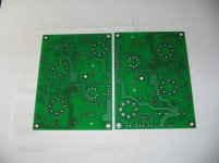
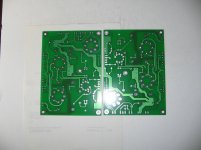
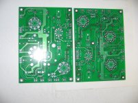
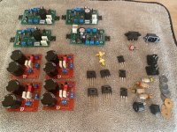
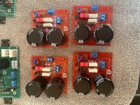
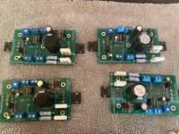
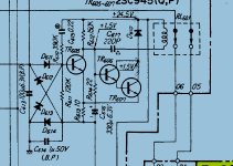
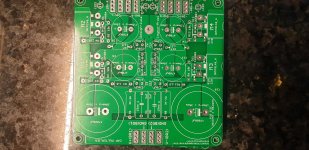
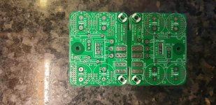
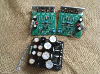
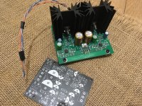
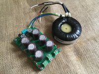
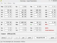
read Ross Hershberger’s detailed build thread from 2008. PCBs to build the crossover are still available; 
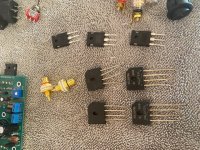
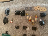
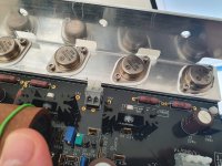
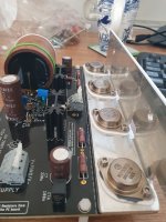
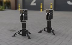
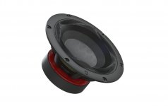
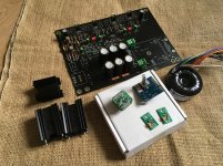
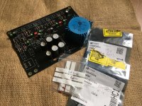
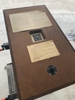
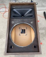
check out the last page of this thread. A pair delivered cost me $32 and comes with detailed instructions and a Parts Express parts list – very efficient! Skills and tools needed are modest: soldering iron, jig saw, drill. If you want to flush-mount a Neutrik SpeakOn NL4 instead of binding posts, you’ll need a 2” forstner bit and 1” paddle bit - see photos. I used a pair of Pyle type PH612 horns with Selenium type D210Ti because I had a pair on the shelf.

My history: I am a big fan of two-way systems and have built some big ones with large format compression drivers from TAD, Altec, and JBL, using wood yuichi horns and cheap metal ones, combined with 15” woofers in boxes ranging from the JBL 3677 cabinets to a pair of monster backloading horn cabs modelled on the 1952 Jensen Imperial plans. I love big effortless dynamics but wondered how successfully could the two-way be reduced in size.

Recently I built a pair of Wayne Parham’s Four Pi speakers with recycled cabinets. I used Wayne’s crossovers, JBL 2226H woofers and the B&C DE250 drivers on Wayne’s H290C waveguides. I didn’t expect the small (relative to the 2” exit compression drivers I’d been using) driver and waveguide to impress, but the Four Pi so successfully integrates the compression driver with the legendary JBL 2226 that I could be satisfied with that combo in any setting. They contend well with the Tannoy dual concentric drivers I’ve been using in bookshelf systems.

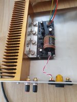
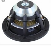
Trying the Econowave version of Large Advents was the next logical step in scaling down the two-ways I’d grown to love. These were sold in massive numbers for years and turn up regularly. I got a pair in excellent condition for $50 at an estate sale two blocks from my house, but of course the woofer foam had long crumbled. I had read that the Masonite woofers are tricky to refoam correctly, and also knew that using the wrong foam would raise the Fs from the spec’ed 17hz to something that would no longer perform so well in the sealed cabinet, so I took mine to a very experienced local guy. I followed Ross Hershberger’s build closely but chose to use a single NL4 connector near the bottom of the rear panel. I like to keep the back flat for easy transport and to avoid anything easily bent or broken.

Results: when I finished these I put them on top of the Four Pi speakers in my workshop, played them for a couple of hours and went through the gamut from Ella Fitzgerald and Coleman Hawkins to Bombino. Even elevated as they were the bass was palpable and solid. Imaging was immediately 3D on a Mapleshade recording. Switching from the Four Pi to these indicates that a better pair of compression drivers would yield audible benefits, and I may play around with that.

Counterpoint: Am I directing you to destroy a classic speaker? These were extremely successful speakers for their price point but the tweeters are the weak point. Large Advents are ubiquitous (I’m aware of more than a dozen pairs of stock ones in my area that haven’t been used in decades) and are more likely to wind up in the landfill than an audio history museum. If you put the effort into refoaming the woofers you deserve to get the most out of the speakers.

And as a result of my conversion I’ve liberated two fried-egg tweeters and crossovers for someone who prefers to restore a burned-up pair to original working condition. Everyone wins!

Conclusion: do it! Find a cheap pair, get them refoamed correctly, follow Ross’s build guide, and you’ll wind up with a great pair of modestly-sized full-range speakers.

Attachments

  • IMG_1142_HEIC.jpg
    IMG_1142_HEIC.jpg
    763.5 KB · Views: 424
  • IMG_1145_HEIC.jpg
    IMG_1145_HEIC.jpg
    982.7 KB · Views: 418
  • CabinetInProgress.jpg
    CabinetInProgress.jpg
    934.5 KB · Views: 438

Jbl 4645c powered by Dayton audio 500dsp

I got jbl 4645c subwoofer for free. 18" driver pro audio. Well actually got paid 400$ to clean out a storage room which had 2000$ worth of quickly sellable merchandise(this story should top those stupid stories " found 2000$ McIntosh at thrift shop for 10$")

Not sure I want to keep the sub but will there be any issue powering it with spa 500dsp.

Jbl recommends 1200 watt pro audio amp. I don't plan on blasting music loud. Just want to try the thing.

I attached spec sheets. Don't like to blow and damage things.

I appreciate feedbacks

Dayton 500dsp seems to be around 230-260watts at 8ohms. I called Dayton once to find out power rating at 8ohm as they don't provide it. Only 500w at 4ohm

Attachments

  • Screenshot_20210428-130043.png
    Screenshot_20210428-130043.png
    825.1 KB · Views: 209
  • Screenshot_20210428-130314.png
    Screenshot_20210428-130314.png
    361.5 KB · Views: 165
Projects by fanatics, for fanatics
Get answers and advice for everyone wanting to learn the art of audio.
Join the Community
507,758
Members
7,887,117
Messages

Filter

Forum Statistics

Threads
406,169
Messages
7,887,117
Members
507,758
Latest member
Cindy