Dispensing Collection of Speaker Crossover Parts
I'm looking to dispense of my collection of speaker building crossover parts.
I'm hoping to do this as whole group. I do not want to part out this out .
I want to make this an attractive buy on the cheap. Several years of building speakers.
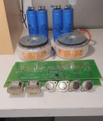
The collection includes several inductive crossover coils (various values gauges), Large and small value film and poly cap. collection (about 20 count). Many values large enough to replace or sub. for electrolytic 20-30 mfd.
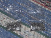
A good size collection of Mills, Eagle, and Dayton resistors for tweeter padding.
A pair of Dayton speaker terminals and an unused 15W 8Ohm L-pad.
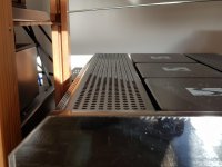
I will be taking pictures. perhaps this should be in a different forum but I just wanted to generate any interest. I'm hoping $25 + shipping would be a good deal.
Yes... most of these items are used but in good shape. I re-measured the crossover coils to verify the values.
I'm hoping to do this as whole group. I do not want to part out this out .
I want to make this an attractive buy on the cheap. Several years of building speakers.
The collection includes several inductive crossover coils (various values gauges), Large and small value film and poly cap. collection (about 20 count). Many values large enough to replace or sub. for electrolytic 20-30 mfd.
A good size collection of Mills, Eagle, and Dayton resistors for tweeter padding.
A pair of Dayton speaker terminals and an unused 15W 8Ohm L-pad.
I will be taking pictures. perhaps this should be in a different forum but I just wanted to generate any interest. I'm hoping $25 + shipping would be a good deal.
Yes... most of these items are used but in good shape. I re-measured the crossover coils to verify the values.


