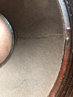
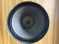
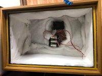
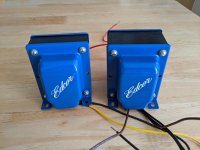
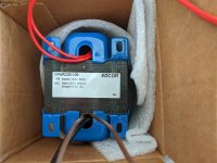
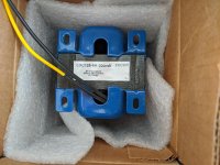
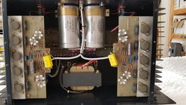
I want to upgrade my Bedini 150 but don't know how

The Bedini 150 MKII sounds good but has been running for 33 years and it's time for a refresh. I've read around the net and two things came up.

1. upgrade the transistors were from the MJ15024 to MJ21194 - NPN

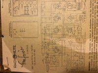
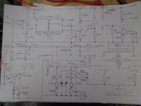
2. change out the yellow caps hanging off the boards to something much better. I don't know what caps these are and can't find a schematic.

Is there anything else I should do? Thanks in advance for your help.

Attachments

  • 20200830_103220.jpg
    20200830_103220.jpg
    731.1 KB · Views: 322

Why does this effects loop circuit oscillate?

I'm working on installing an active (solid-state) effects loop in my 1969 Bassman. It was originally AC568, but over the last couple decades it's had some mods (AA864 phase inverter and a 2204-esque preamp on the Bass channel).

I gathered all the information I could get my hands on, and cribbed bits and pieces from different places to come up with the simplest circuit I could manage. It uses an IRF840 for the send buffer, and an LND150 for recovery.

I'm having a devil of a time with oscillation (90-120kHz) and motorboating (~4Hz). The buffer seems to be fine, so the problem appears to be on the recovery side.

I've tried multiple different tweaks along the way, including fixed bias for the LND150, lots of different values for Rs and Rd, lower Rg (down to 47k), high-value gate stoppers (up to 68k), etc. The closest I got to clean was using fixed bias at ~15V, but it still motorboated when the master got above about 7.

It oscillates even with volume, send, and return all turned down. Motorboating starts as soon as the return or send is turned up a little. There are some combinations that don't oscillate; in particular, turning the return all the way up makes it more stable (although there are still plenty of send pot positions that make it freak out again).

Notes:
  • Some items have been omitted from the schem for clarity - 12V protective zeners on both MOSFETs, bypass switching
  • It's currently built on miniature breadboards. I've left at least one empty row between all connections. They are sitting between the power transformer and the tagboard. Lead dress isn't great, but there aren't big gobs of wire floating around.
  • B+ is sourced from the last preamp node. Yes, 220V is super low; the Bass-side preamp flows a lot of current, including the previously-unused triode.
  • Voltages are at idle - had to disconnect the return to get there.
  • I ran out of 100nF caps, that's why there are 150s in there.

I swear, everything single project I touch oscillates like mad. It's crazy-making. I spent eight hours today trying to resolve this. That's eight hours I would much rather have spent playing. I've easily spent three times as long chasing oscillations than I have doing everything else combined (designing, building, etc.)

I feel like I'm missing something dumb. What is it?

POz1mhb.png

For sale or trade - Leak stereo 50

Hey there.

I have a Leak 50 stereo that I had originally intended to use for the transformers in a stereo amplification system for an instrument/line level.

I removed the transformers to test them. Both output transform coils all are intact and gave dead on values when I performed an ac voltage inputting test and did the math for impedance ratio to validate that the taps were what they supposed to be - both transformers 4, 8 and 16 ohm taps with a primary impedance of 7,000 ohms. The power supply also measured predictable voltages across its coils - HV, 6.3V and 5V. Of course, they measured a little higher due to the no load condition on the PT.

A poster responded to my thread on this amp with the comment that this amp could be very valuable to someone who was passionate about restoring rare vintage amps, and that I would be equally or better found in using say, the Dynaco replacement transformers as found at Triode Electronics.
After some thought (and a little guilt) I decided that perhaps this would be the way to go. Maybe myself and who ever go their hands on this amp would be much better off in their venture instead of raping a rare vintage amp for its transformers. Don't get me wrong, I was very excited to use the trannies for my next project but, would probably do fine or better with something like the Dynaco replacements.

So, if you are interested, feel free to contact me, you can even call and we could facetime - I could show you the amp and transformers as they are and perform any testing that gives you confidence in the tranny functionality.

Thanks for coming by,
Best,
Philip Donovan
617-470-9821
donovanphillyboy@aol.com

Ghentaudio RTX modules

Hi, just ordered a 125asx2 off ebay and a case from Ghentaudio. I was hoping to run this module in BTL mode and see that i need a converter to go from unbalanced to balanced.

The RTX module from Ghentaudio performs this task. There are 3 options,

1. 6gb gain 10kohm
2. 0db gain 10kohm
3. 0db gain 100k ohm

Which one do I choose and why?

Tks in advance for your replays

Plan on running these amps off the pre of my denon avr x4100

Salvaged Hammond AO-68-1a

I have salvaged from an old Hammond Organ, an amplifier. I would like to convert it to a guitar amp. It is an AO-68-1a. It has something else that plugs into the chassis that has a 12ax7 and an ef86 tube, this 2 tube setup has its own mini chassis with a male plug that plugs into to its partner. The mini chassis has a printed mark on it that identifies it as a AO-64-1. Does anybody have any info on this set up? Thanks in advance!

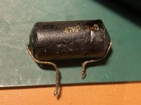
Is this a capacitor?

This component - it was connected between pin 4 and 6 of the 7C5 in the schematic. My LCR meter says it's a 55nF capacitor. "47KP" could perhaps mean 47 000 pF.. makes sense? There's also a .05uF cap in the schematic. Stuff isn't exactly connected like there though, so can never be sure.

However, why the strange markings? All other caps in this radio from 1949 are properly marked, no voodoo.

Attachments

  • 5D74F25B-7B09-4CED-B113-AB1B7E7ABF80.jpeg
    5D74F25B-7B09-4CED-B113-AB1B7E7ABF80.jpeg
    355.8 KB · Views: 398
  • 3D53A700-A48D-4016-AC94-2B40A5CBED63.jpeg
    3D53A700-A48D-4016-AC94-2B40A5CBED63.jpeg
    527.7 KB · Views: 391

Mark Johnson's VRDN Bipolar PS for Line Level +/-11 - 20V Circuits

Folks:

I just finished a very successful mini group buy for Mark Johnson's H9KPXG soft start boards and, like every other junkie, want to do it again. This time, I'm considering a group buy for Mark's VRDN bipolar power supply for line level circuits. There is a wealth of technical information regarding this board on Mark's thread: VRDN: bipolar regulator PCB for line level ckts: ±11V to ±20V @ 1.5A with "De-Noiser"

The purpose of this post is to assess whether there is enough interest to justify my hosting a group buy. I'm looking for likely buyers but not expecting a commitment; you have to be satisfied with quality and cost. My intention is to get green 1.6 mm thick ENIG-RoHS 2 oz copper pcbs. Let's assume pricing will be under $5 per board plus shipping (worst case for domestic purchasers is $8.30 for USPS Priority Mail, but I may be able to use less expensive padded mailers). Non-US orders are invited, but keep in mind that while I don't intend to profit on mailing expenses, you might be better off having the boards made yourself.

Is anyone interested?

Regards,
Scott

Miracle tube design formula for class AB1 Beam Pentodes

I was looking at the notion of a typical Sweep tube / Audio power tube design being just a re-scaling of a basic 6L6GC (for example). Higher power = bigger plate, higher current rating = bigger cathode. So it seemed natural to expect some simple relation to the 6L6GC for the typical selection of an OT primary impedance too.

Since power scales as V * I or V*V/Ro, and impedance as Zo=V/I, a simple formula derivation would be:
W = V * V / Ro
so V = SQRT (Ro *W)
and the OT Zo = k deltaV/deltaI
k is a "constant" to be determined from typical tube/OT datasheet specs

so the magic formula is:

OT Zo = k SQRT(W)/Idc

the 6L6GC bogey Ro getting absorbed into the k for convenience, W is the tube plate Watt spec and Idc is the tube's max DC current spec in milliamps. (usually on the datasheet )

This formula assumes B+ and Idc current will BOTH scale as SQRT of the Watts spec ideally, with the Idc term in there to modify the scaling for tubes designed with a different balance of I to V versus the 6L6GC. Ie, if a scaled tube handles twice the Watts, it would be expected to handle 1.414 x the voltage and 1.414 x the current, so would use the same primary Z OT then. The Idc term fixes deviation of the scaling for different V to I design ratios from the 6L6GC.

Looking at some typical tubes with datasheet spec'd OTs for maximum power output, some typical k values:

6L6GC kSQRT(30)/110 = 5600 Ohms, so k = 112466
6973 kSQRT(12)/45 = 8000, so k = 103923
6AQ5 kSQRT(12)/40 = 10000, so k = 115470
6V6 kSQRT(14)/40 = 8000, so k = 85524
6CA7/EL34 kSQRT(25)/150 = 3400, so k = 102000
6550 kSQRT(42)/190 = 3500, so k = 102612
6BQ5/EL84 kSQRT(12)/65 = 8000, so k = 150111
8417 kSQRT(35)/200 = 3500, so k = 118322
7591 kSQRT(19)/85 = 6600, so k = 128702
6146B kSQRT(27)/175 = 4000, so k = 134715 (5600 Ohm case was right at the max B+, so didn't use it)
6BM8 kSQRT(7)/50 = 7000, so k = 132288
4D32 kSQRT(50)/300 = 3000, so k = 127279

the variations of k above are largely from deviation from the SQRT(W) term for B+ variation with Watts expected, versus the tube design models actually used from the datasheets.

for TV Sweep tubes, the Watt rating is generally more conservatively rated due to the constant high-stress usage in that mode. So for these I multiply the given Sweep Watt rating by 1.333 to use here:

6GE5 kSQRT(23)/175 = 4000 Ohms, so k = 145960
6HJ5 kSQRT(32)/280 = 3000, so k = 148492
6LX6 kSQT(44)/400 = 2500, so k = 150756
6LW6 kSQRT(53.3)/400 = 2000, so k = 109579
42KN6 kSQRT(40)/400 = 2000, so k = 126491

Well, these #s are not written in stone by any means, but maybe guidelines I would say for plotting a 1st load-line on the plate curves graph.

The B+ available would affect the load Z choice obviously, and efficiency goes up with higher B+ and higher load Z.

One needs to check that V and dissipation ratings are not exceeded. The screen V would be selected to just enable the max current on the load line.

Distortion is another matter for pentodes, since there is typically an optimum load Z due to screen current distortion at high load Z setting in. The later TV Sweep tubes typically had reduced screen current figures shown, so that allows using a higher load Z without distortion increasing. 21LG6A being a good example, very straight lines for plate curves. https://frank.pocnet.net/sheets/123/6/6LG6.pdf

Constant k in the above formula assumes B+ and OT Z will scale up or down as the SQRT of Watts (with modification for the cathode size deviating from SQRT(W) also). Since the 6L6GC starts at 450V B+ here, this may not be a desirable scheme if trying to stick with lower cost electrolytics in the power supply for bigger tubes. In which case, one should scale from the 6L6GC using current only (so a modded formula then: Zo = k2 / Idc, with different k2 factors from the datasheet models ).

Just having some fun looking for patterns.

Just for curiosity:
211 tube kSQRT(100)/175 =9000, so k = 157500
300B tube kSQRT(40)/100 = 7000, so k = 110679

Hmmm, works OK for triodes even. Upgrade that Magic formula to Miracle formula!
Single ended amplifier with these transformers

Hi, it's my first post and I'm really just getting started in this hobby so please bare with me.
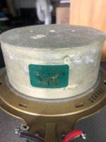
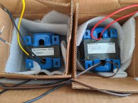
I recently found a great deal on a pair of power transformers rated for 120v/60hz suitable for tube amplifiers. The first issue is that I live in Italy where we have 230v/50hz power outlets (actually in my house it's closer to 240v). The previous owner had connected the primaries in series and built two monoblocks, which is also what I was planning to do, but I have read arguments against this approach, so I'd love to know your toughts. I'll leave a picture of one transformer attached.

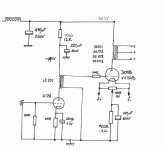
The second issue is that the previous owner's schematic lacks the power supply circuit (which I'm not able to design myself as I'm quite the beginner, the most I can do is test something in PSUD2) and uses an interstage transformer which is both hard to find and expensive, whereas I'd prefer to use the usual coupling capacitor approach to save some money there (I'll attach the schematic of this circuit too).

So I was wondering if you have some schematics laying around suitable for my power supply to build some kind of single ended power amplifier. For what I've seen my voltage and (especially) current ratings are limiting me to build 300B SET monoblocks (which I'm totally fine with).
The amplifier won't need to be that much powerful as I have a small listening room (4x3.5 meters) and good-enough efficency speakers at 91db/1W, so I guess an 8W output (as I've seen in many 300B SET designs) will be more than enough.

Attachments

  • transformer.jpg
    transformer.jpg
    86.5 KB · Views: 293
  • schematic 1.gif
    schematic 1.gif
    40.5 KB · Views: 326

Cant figure out Feedback Path Sansui 7000

According to block diagram, this old cap coupled Sansui gets it feedback unto TR802.

Question: Is the feedback network the C804/R806 connecting emitter to ground or does the feedback signal come through R808 to the collector of TR802, with "balancing" taking place through C803 Collector to base ?

Sorry - if this is obvious, I am just begining to learn, usually it is clear what the path is. Thanks!
Attachments

What Volume Control Potentiometer Value To Use?

What Volume Control Potentiometer Value To Use?

I am experimenting with some basic transistor receivers and I am wondering how critical the volume control resistance is.

I know that most of the time its recommended to use a audio / log type of potentiometer but always wondered if I could use a 10K instead of a 5K ? and what the trade off or consequences be ?


Frank

Power Supplies for TPA3116 (18650)

Hi all,

Speaker building is my hobby and I am in that area for around two years.
I'm building portable Bluetooth speakers based on TPA3116 and a power supply this is an important thing.

I have high current batteries 18650. One battery can give 5A max.

What is my purpose:
1. Use only two 18650 batteries.
2. The battery connection scheme can be parallel or serial, it depends on the step-up module.
3. Output of power in watts from this amplifier must be clear 15W per channel without clipping.
4. I will use speakers with impedance 4 Om.
5. Output voltage from batteries must be stable, that means when battery discharge, input voltage on amplifier must be without change.

Based on the datasheet of TPA3116 for 15W per channel for 4 Om I need around 12V and 3A.
I need to use the dc-dc step-up module to cover all my goals.

Parallel battery connection scheme:
Two batteries give 4.2V max and 10A max = 42W. I used the dc-dc step-up module based on XL6009 and as a result, I couldn’t get a clear sound with 15W. Moreover, the voltage after the step-up module went down on high volume.
Serial battery connection scheme:
Two batteries give 8.4V max and 5A max = 42W. I’ve got the same result as with a parallel connection with XL6009. Moreover, I used the dc-dc step-up module based on U024V and I didn’t get any success too.

And in the case with a dc-dc step-up module that can give a negative effect on the sound.

Questions:
Could you please recommend to me the best dc-dc step-up module for speakers?
Could you please share with me your experience with power supply and portable speakers?
What is battery connection scheme better for all my goals?

Need help with transistor selection

Hi, I need some advice on what transistors you guys would advise for the input stage of an amp running +-45V DC rails.

Also need giudance on a good selection for the smaller transistor to pair with the C3503 VAS transistor.

Im kinda limited to RS components, and dont want to order 100s of transistors.

Any help would be great.

Was using 2n5551 and 2n5401, dont have any left.

DC offset in original B1

I've built a few B1 buffers, but have become concerned about the initial level of DC offset since I bought an SVS SB-3000 with its 800 watt amp.


Initially, the units output about 150mv of offset, which dies down to nearly zero within a few minutes.


It is that first few minutes that worries me, particularly with the sub.


I know that I can just wait to turn on the amps, but this negates the ability to use the automatic turn on and, more importantly, annoys my wife who just wants music without any annoying complications.


Is there any way to block this DC offset from the get go?

Clamper Trouble by Philips Loader L1265/51 in use by Primare, Cyrus DAD3 NAD S500

Clamper Trouble by CDM12.4 Loader L1265/51 in use by Primare, Thule, McLaren CD20R Cyrus DAD3 and NADs500

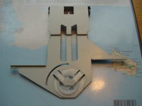
The image of this clamper you will find in the attachment.

This loader (Philips order code) "3104 147 02481" is in use by follow so called "High End Audio" compact disc player models (only PCM read):

1) Tag McLaren CD20R + CDT20R
2) Cyrus DAD3
3) NAD s500
4) T+A CD 1210 R, CD1220 R
5) various other models like e.g. Quad 77, go to
http://www.diyaudio.com/forums/digital-source/180483-problem-quad-cd-77-help-needed.html
Creek, Audiolab 8000CD, Primare D20 and D30, SONIC FRONTIERS SFCD-1 (please note: only partly equipped with this loader, in any case there is to find it's predecessor, the loader 1210 resp. L1210).
More details to this loader are to find there:
http://www.diyaudio.com/forums/digi...ayer-models-loader-l1265-l-1265-cdm-12-a.html

The main issue by the clamper unit of this loader is a difficult to describe knocking/tickling noise (mechanical noise, to hear from the rotating disc and not from the speakers) in combination with an unwanted suspending playback until stopp mode occurs.

Some years ago I order the appropriate new parts from Philips (Clamperplate 4822 466 12037 and Clamper 4822 466 12038 so as the plastic chassis No 46 and 41) and the issue was solved.
Currently I look for a used CDR765 to get this parts, because for the playback loader device (not for the burner device) the same parts are in use - unfortunately the only possibility at the moment.

But the actually reason for the knocking/tickling noise I haven't find out until this day, because this is temporarily and not permanent audible, also independend of the thickness from the compact disc itself.

Actually only the following errors must be exist:
1) White plastic clamper roughened or bad lubrication, thus increased friction resistance on top to the clamper plate
2) Plate and clamper a bit warped/deformed
3) Plastic chassis devices from the loader a bit warped/deformed

Who knows (resp. how I can find out) the exactly reason for this?
Maybe one of the members have a associated advice from Philips (Service Bulletin-Repair Tips).

Thank you for your advices.

Attachments

Daphile Replacement or not?

I currently run daphile beta on a stand alone mini pc and Plex on another, seperate mini pc. Both with the medi stored on a seperate NAS.
Most of my playback devices are Squeeze devices or derivatives thereof.

This all works apart from in Daphile I can't see any way to change the location of playlists to a folder on my NAS where the music is stored.

In LMS itself it is a menu option but not in Daphile.
As Daphile is based on LMS I believe it should be possible to edit the appropriate file to set this up. But I can't find any reference to this anywhere.
I have asked on the Daphile thread here and elsewhere and on the Daphile facebook page. But I get no response.
I love Daphile in itself and would love to keep using it but for this one problem.
So, should I accept defeat and move on?
If so what to?
In the past I have used LMS on Linux and Vortexbox.
I have also looked at but never used Snakeoil OS.
I like the playback qulity of Daphile, altough I wouldn't class myself as a true audiophile these days. I'm just struggling with the configuration flexibility of it.
I found Vortexbox to be a bit behind the drag curve in terms of upgrades. Plus there seems to be some doubt over it's long term support.
Any input on the alternatives I mention or ay other alternatives apreciated.

SB Bromo kit Port dimensions?

Hey guys, I am in the process of building the Bromo kit from SB and I cannot find the port dimensions anywhere!

There are none mentioned in the kit info except that the cutout should be 73mm.

Madisounds site for the Bromr kit says 2in. dia. and either 6 or 7 inches long....

Can anyone help me to find the right info?

I dont want to cut holes without knowing for sure what the proper size is.....


Thanks!!!

FS Altec 414 z and Tango 4-16 ohm

Hello ,
I would like to sell
1: Altec 414Z 16 ohm pair one is need to recone and one is good condition
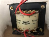
2: Tango transformer for speaker own matching
4,8,16 in 4,8,16 out pair

Altec 414z $ 200
Tango MT122 $200
If u take Both for $330
Price is without shipping and PayPal

Ship to us only

Best

Attachments

  • 7FC1A889-F7D3-4325-88E4-E1347FF9E863.jpeg
    7FC1A889-F7D3-4325-88E4-E1347FF9E863.jpeg
    394 KB · Views: 151
  • A4C8E966-00BE-4ED8-8547-EA307BB05EB0.jpeg
    A4C8E966-00BE-4ED8-8547-EA307BB05EB0.jpeg
    705.7 KB · Views: 159
  • 07CA9500-D665-40F8-9A31-7D21849D8EAD.jpeg
    07CA9500-D665-40F8-9A31-7D21849D8EAD.jpeg
    449.6 KB · Views: 155
  • 447E4DF4-21CA-4875-817E-445038A48AEB.jpeg
    447E4DF4-21CA-4875-817E-445038A48AEB.jpeg
    330.7 KB · Views: 150
  • F28B4FAA-3B63-4FBA-A0D4-4E8716E4F66D.jpeg
    F28B4FAA-3B63-4FBA-A0D4-4E8716E4F66D.jpeg
    376.8 KB · Views: 153

Power On for relay controlled volume pot in 2 x mono

Take two mono pre or power amplifiers, each with their own power on/off switch. For the simplicity it is assumed the two amplifiers are in the same case. They are wired as 2 x mono; only and directly connected by ground via the case.

A classic approach to add a volume control is to add a mono potmeter of appropriate value to each amplifier. Instead of a standard potmeter, also a relay controlled volume pot or a digital volume control can be installed. As with a standard potmeter, a relay controlled volume pot will always be connected at some resistive value.

Still a challenge emerges, as a separate power supply for the volume control is required: how to activate the power supply for the relay controlled volume unit? Options are:
a. add a separate mains on/off switch for the volume control, and always turn this on first before turning on the amplifiers. The mains switch may even be always ‘On’ so the volume control is continuously in ready state.
b. connect the power supply to the power on/off switch of one of the amplifiers.
c. create a current induced mains on/off sensor after both of the mains switches of the amplifier. This sensor then will activate the power supply of the volume control. This way whichever amplifier is turned on, the volume control will switch on automatically.


Question 1:
Do you have experience with one of the above options, or maybe with another option?

Question 2:
The option c. for a current sensor at the mains of both amplifiers is appealing. However, a search on this forum and on internet did not yield yet any suggestion.
Do you have a pointer for a design?

Compression drivers matched or not?

Hi,

i built my first pair of speakers and when making the crossover I noticed that the compression drivers are not 100% identical in frequency response. At around 2,2kHz there is a difference of about 4db. We are talking about the HF10AK measured without horn in about 1m distance. In the final speaker with the horn I needed to EQ this part heavier plus one driver is 1dB louder than the other. Would you say this is normal? Are they in tolerance and matched close enough? Or should they be closer together?

With the DSP I can get a flat FR. But let's say you want to build a passive speaker from Humble made hifi and you buy this pair of drivers. You would have a 4dB dip in one speaker. Not cool...

Attachments

  • CD.jpg
    CD.jpg
    155.5 KB · Views: 232

Jeff Bagby Kairos vs JBL L82

Hi,
I have the Jeff Bagby Adelphos (Kairos with flat panel) and I'm thinking about buying the JBL L82.
I can audition the JBL in a store but I'm not sure it would tell me how they compare to the Adelphos...
Is the JBL would be in an upgrade? Or even interesting to the Adelphos?
Any thoughts?
Sorry if it not the right forum for this it's just not a lot of people in regular forums familiar with the Adelphos.
Thanks!

Holey basket Coral's.....?

I had 4" holey basket Coral's in colset for a long time & thought time to hear them, I installed them in sub baffels & ran direct to 300B in PP, then Vifa M26wr -09-06 on the bottom driven by BASH 300S amps. set @ about 100hz.. . fired it up & did not expect much at all..4"....? what could they possibly do well. I was shocked.....they blend perfect with the Vifa's. for bottom support & no x-overs of any kind on the Coral....Woerd thing is I hear absolutely no need for a helper tweeter,,, abviousley don'y need it type deal....only thing is I probably am running to much powr in the little thing as the Canary is a 22w amp.. holding so far & don;t see scary sh. with the Coral....very sweet & detailed everything & very extended......this I don't understand, but it is.... I wonder if I should run them mounted on the back of the sub baffle, I might try it.......I hate x-overs in the critical music area.. & these little guy's are very promising indeed. they beat my Fostex fe167e's, for everything I like.....No shout....very cool stuff, never thought they would sound good, they flat ROCK.........
DSC02568.jpg

Audio Research Preamp Power Supply Question

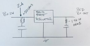
I have 2 ARC LS (line stage) pre amps that have some years on them. One is in really good shape, the other needs a lot of love. I plan on NOS tubing and new caps. I'm not posting the schematics, but I have a question on why these 2 units have resistors into the power supply filter capacitors and one has a very small rf coil, which to me bypasses the resistor anyway. They both are similar but not exactly the same. I drew a rough pencil sketch. I have been building tube equipment since the 80s and I've never seen anyone put a resistor to the filter cap, unless is was to series drop the voltage for other stages, which these clearly do not do. It looks like it would simply make the caps less effective. 😕

Attachments

  • power.jpg
    power.jpg
    28.9 KB · Views: 144

1/4" (6.33mm) split Speaker Off, A, B A+B

I am pretty new to working on things and was unable to find a thread with good recommendations, i think the issue is .. i have no idea even what the proper nomenclature for the part i am looking for would be.

I have seen a variety of old receivers come and go through my hands and a common problem is old switches that have been sheared off or other ..

Currently i have an old Nikko NR-1015 with a broken shaft on the speaker selection switch the settings are Off, A, B and A+B it appears the positive amplifier runs to this and is passed accordingly while the negative appears to run right to the terminals. similar to a home light switch)

I am looking for a suitable replacement but there are a lot of terms with regard to polls and such i am not sure what the right description for this switch would be for a company like C&K switch' or others to even know what to search for 🙁

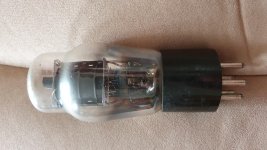
Is this a 41 valve?

I suspect it's a faulty tube in a radio I'm repairing.
Definitely looks like a pentode from what I can tell.
It's got a ux6 base and definitely a 6 volt heater.

I've put it on my tester and it arcs inside when applying the HT and the overload light comes on.

Not sure if it's because the tube is faulty or if it's the wrong type set on the tester.

Attachments

  • 20210524_114328.jpg
    20210524_114328.jpg
    987.3 KB · Views: 321

M2X/Yarra Format Breakout Board

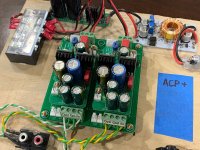
This is a handy little board that is great for experimenting with the various M2X or Yarra front end daughterboards. It contains provisions for power input and signals in and out via both screw terminal blocks AND Molex KK/JST connectors (your choice). It is a great way to test out new FE boards, or to even use as the basis of a very compact and low cost preamp system. It will work with the assortment of preamp or FE modules that we have so far including: Melbourne (TH and SMT), Pass WBA18, Pass ACP+, PCA, Hakuin, Pete Millet Korg 6P1, Pass H2+, OPA454, HV DC/DC converter for OPA454, and the new Experimenter's board by Puijkh.

Here is a partial collection of the boards available:
837790d1587844132-yarra-preamplifier-hpa-melbourne-db-buy-yarra-modules-family-01-jpg


Here is the Breakout Board PCB:
attachment.php


Here is an example of me using it for an Pass ACP+ preamp/headphone amp:
attachment.php


Schematic (not much to it) - note well that the input and output GND paths are separate and need to be connected via jumper to make them common fo rmost cases.

Attachments

Midbass module as helper woofer / kinda FAST / WAW

Premise: I want to build all the Full Range speaker designs. In all seriousness the best way to figure out what you like is to try them all right?

The problem is that my space is super limited and I'll never really be able to have more than one pair of speakers out at a time.

The proposed solution would be to build a pair of something like the rythmik FM8 (dual 8" subwoofer 20hz-250hz +-3db.

Why not buy the Rythmik? My first thought was that they're expensive, but I eventually got over the cost because I think this is going to be expensive either way. The real reason is that I'd gladly trade those last 10hz on the bottom for 1000 or even 500hz on the top. The FM8 is 12w x20h x 16d.

I looked at the SDX10 and even the 12PW, but it looks like they're going to want significantly larger boxes. Anyone build something similar that's a better fit for my needs than the FM8?

These would ideally allow me to create smaller versions of many of the designs here and give me the latitude to cross them over 200-500 range.

Thanks

Zarathu's Line Arrays

Only one tiny mention of a full line array......

Mod Note: This thread was split off from here

http://www.diyaudio.com/forums/showthread.php?s=&threadid=100195

dave :cop:
______________________________

Once I experienced a line array system, I never had any interest at all in going back to MINIATURE MUSIC. Now some people have been brought up on miniature music and don't want to hear full sound in their house, but I do.

Prior to building my line array(took me two 1/2 years including the learning curve), there were certain kinds of music which I could never listen to and in any way confuse it with the real thing: top of the list was piano and organ.

Since my line array is finished, I could swear there was a fella playing a grand piano 10 feet from me, or that I was actually in a church listening to a full pipe organ.

The heck with middle speakers, and back speakers, my full three way line array puts me inside the near field without reflections, and all the ambience, and reality is right in my face as if I was really at the performance. The ONLY thing less real is that my front wall is only 12 feet wide so a symphony orchestra with a 35 foot front is shorter. Last night I was listening to Michael Murray playing Toccata & Fugue in D minor(organ), and after 6 months of listening I could still say an unequivocal, "WOW!" at the end.

Go for full size music, not MINIATURE MUSIC.

Email me if you want a full description of my system, and how much it cost( less than $1600, including electronic crossovers, and Tri-Amping)

Zarathu
calipso@epix.net

SB20PFC30 + TC9FD18

I'm planning on building some speakers for my workshop. I will be using the SB20PFC30 8in woofer. As for the mid-high, I'm hoping I could get away with TC9FD only. Judging by the datasheet, it doesn't do well off axis in the high range, but for these kind of speakers I don't think it matters.
As for the circuitry:
- active crossovers and bi-amplification: I already have boards for crossovers and amps, plus everything will be in the enclosure
- passive crossovers: no experience with them whatsoever; I could do measurements and plug them in that crossover app, but it's more complicated; the advantage is that I already have the amp for them
- if a 3-way is recommended, the woofer will be powered separately and the mid + tweeter will have a passive crossover

Winisd simulation:

WBCYejL.jpg


TFf8fTW.jpg


Sketch:

HjLw1Kp.jpg

raspberry pi 4 sound issues !

hi when i first got the rpi4(running raspbian) i noticed it totally lacked in sound quality, so i purchased a "DAC hat"(iqaudio DAC-pro) and installed it. i found that the DAC hat just increased the volume of the already terrible sound.
after reading that others have had problems with pulse-audio i tried many other distros, but all had the same result. i'm currently running a totally stripped down version of armbian with pulse-audio totally removed, and am still having the same problems!!

my issue is that the mid range seems "closed in", the treble is very "harsh" at high volumes and the sub-bass is attenuated to the point that its missing, the sub-bass starts to get attenuated at about 100Hz and is just a whisper at 30Hz, i no longer get down to 20Hz !!

any help resolving this problem would be appreciated

gaz

Valve heater power supply for SE amp

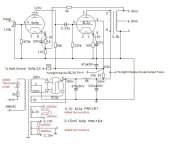
Hi all, this is my first post on this forum. I would be really grateful for some help please with the heater wiring on a cheap Chinese SE amp I have just purchased off Ebay. The seller has sent me the schematic for the amp which I have attached. He has highlighted in red some changes he has made to the PSU involving addition of a thermistor (good) and 4 x 100 ohm resisters added in the heater supply circuit. I can understand the reason for the two 100 ohm resistors added to the 6.3 volt (3.15-0-3.15) centre tap supply to the 6n9p valves, but I am unsure of the impact of adding the two resistors to the heater supply to the EL34 valves where there is no centre tap on the transformer. The way they have been added means that two resistors in parallel produce a reduced resistance of 50 ohm and additional current output. I wonder whether it would it make more sense to just remove one of these resistors in this section so that one end of the 6.3v winding is then grounded by that one remaining resistor. Many thanks indeed. Russell

Attachments

  • Valve amp circuit.jpg
    Valve amp circuit.jpg
    56.4 KB · Views: 242

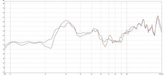
DIYSG "Elusive" 1099 measured!

Thanks to a local who loaned me his 1099's, I was able to put them on my Klippel Near Field Scanner and get full SPINORAMA data for these speakers. I have also provided additional data such as impedance at varying levels, distortion and a few forms of my own compression tests. It would be a nightmare to link the images singularly here so I'm going to link to my website directly:
DIYSG 1099 Speaker Review

NAD 2600 Power Envelope Stuck in Protection Mode

I recently purchased a NAD 2600 that appeared to be in beautiful condition - it was never worked on and cosmetically looked 10/10. It was clear the amp was rarely used and babied. However, once I plugged it in and powered it on, the protection light came on immediately and stayed on. This happens with or without any speakers/inputs connected.

What I have done: I took off the cover and checked all the fuses - each appears to be intact.

I looked at all the components and none seem to be burnt out - none of the electrolytic capacitors are bulging and no resistors are burnt.

What I have looked into: I have read up on the protection relays and do not this this is the issue because protection stays on. From other forum posts I have read, it seems like checking voltages is the next step.

My questions: Is there a good guide for how to safely power on an amp and check voltages hot? I have HV electronics experience but nothing on amps. Are their components that are known to go bad with age on this amp that I can check? I have a bench top multimeter and scope on hand. Has anyone had this issue and knows where to start?

Any insight or references would be greatly appreciated.

Thank you,
Josh 🙂

Small two way speakers with 3 or less crossover components.

HI Gents,

I ran across a review of the Triangle Titus 200 mini monitor: (Product Review ) which said it sounded great and used only a single capacitor as a crossover.
I love building speakers and have built some with 9 or more components in the crossovers which sounded very good, but am wondering if it is possible to substantially reduce the number of components and still get very good sound. If anyone is aware of a proven design that is small (10L or less ) and has a 3 component or less crossover, I would greatly appreciate hearing about it.

Thanks!
Jay

Impressed with the ACA 1.8s

You guys may remember that (with all your help; much appreciated and many thanks!), I built up a pair of ACA 1.8s last summer while I was recovering from a total left hip replacement surgery. I based my build on Tungsten's premium parts protocol.

My plan was to use these with a pair of Danny Richie's (of GR-Research) Encore X-LS standmounts that I was built up at the same time to stay with the DIY theme.

I got really busy with reviewing and writing up three simultaneous full-length reviews for TAS in Q4, 20 and first part of 2021, and as I just finished up my latest review, of the Fidata HFAS1 network audio server, I decided it was time to set the X-LS Encores and ACAs up again.

Moreover, I also recently found out from Danny Richie, that in contrast to the 25 hours or so the guys in the GR-Research circle at Audio Circle told me the X-LS Encores speakers needed to run/burn in, with the premium parts I used, notably the Mills resistors and Miflex copper caps, they actually needed....400 hours! 😱 Time to get some hours on these boys....😀

Long story short, I set them up as my Mains for my HT setup and ran up about 240 hours on them over a period of some weeks (I kept track in an Excel worksheet). As I was about halfway through the burn-in process, though I'd give them a listen, and at the same time, get some hours in on the little ACAs. I'm running mine as a pair of bridged monos.

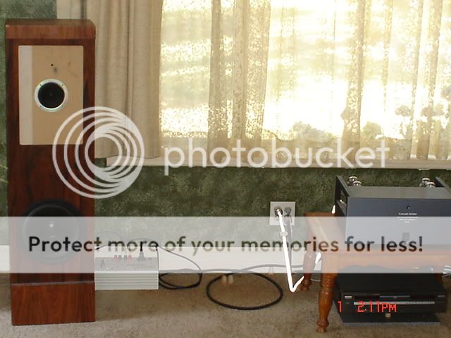
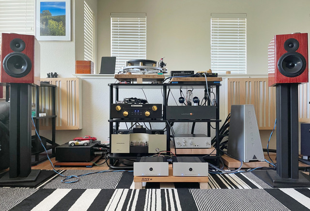
Here's a shot of them set-up at present. My Harbeth 30.2s have been moved out of the way for the time being. I also have a new DAC, the Lampizator Baltic 3, which I bought after writing the review for it (middle right shelf; amazing DAC).

DIY-Stereo.jpg


So....after listening for 4-5 hours/day for since the beginning of the long Memorial holiday weekend, I've also noted that the ACAs are getting better and better and better, too.

And, in a really nice way. When I first built them, they sounded nice, quite pleasant, but were a bit closed in at the very top, and somewhat recessed-sounding. The mids were nice, but highs were not as open, extended or airy as my reference Conrad-Johnson LP70S power amp.

Well, that's all changing now, the ACAs have really opened up in the top end, the presentation is becoming much more fleshed-out and the amps actually are becoming more resolving and transparent, yet liquid (mellifluous is probably the operative word here), and, it seems,...quieter. I'd estimate i've got about 40 hours on them, and I expect they will continue to improve as they march towards 100 hours or so, but...Dang! Color me really impressed. These bad boys really do...music.

Here's another picture of them, closer-up. The fact they're plugged in to a Shunyata Everest power distributor, with its massive QR/BB device, with my Lampi as source, and being driven by my First Sound Presence Deluxe preamp likely doesn't hurt, either. 😛 Woot!

ACAs.jpg


Think I'll discuss with my editor, Robert Harley, writing up a "DIY" article for TAS on the ACA 1.8s. Stay tuned...

Cheers.

FS: BPBPP Bruno Putzeys balanced preamp

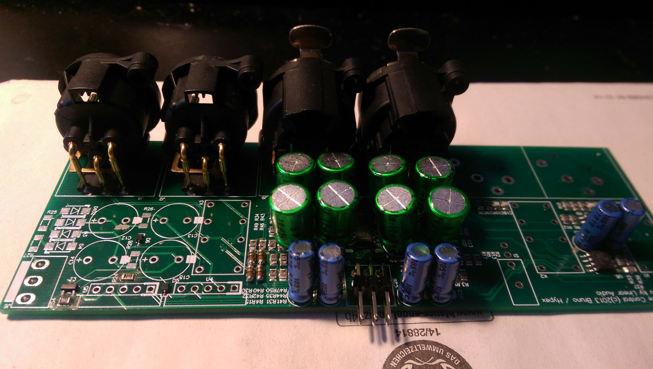
Due to some change in audio system, I would like to sell my nearly finished BPPBP. All of the SMD components has been populated. The resistor are Susumu RG 0.1% 25ppm. 8 important resistors are Susumu 1kOhm 0.1% 10ppm. Opamps are LM4562 & OPA2140 (for DC servo). Capacitor are Nichicon Muse ES & KA

You only need 3 relays, a pot & power supply to finish that high quality preamp

Price: 45€ + shipping cost.

IMAG0061.jpg

USB PD - Power delivery

As todays consumer electronics has growing number of USB type-C Power Delivery support, and chargers are also available, I am considring this as an option, at least for headphone amplifier use.


Because I have little experience in this topic, I would like to ask You, what do You think about this, and whether having PD power supply for DIY audio projects does have any benefits or drownbacks.


According to TIs website, there are ICs available with support of 20V 5A, as PD supports 100W delivery. One problem could be using the QFN packages.


It would be possible to make a modern universal PSU for low demand projects, with little space needed.


My work setup has evolved to use one cable.
I can charge my laptop, and have external monitor the same time. If I need to charge my phone, I plug in the same cable. Then it would be obvious, to plug in a headphone amplifier for example when I need it.


Does anybody have experience with PD? Opinions are highly welcome as well. 🙂

SS preamp and tube amp - not the other way around?

This seemed a little too general for a specific forum here.

It is very common to see the suggestion you get a tube preamp for that 'tube' sound but buy a SS amp because it is a heck of a lot easier to live with, more powerful, cheaper, etc. (vs. a few preamp tubes).

I am getting ready to pull the trigger on a new (stereo) preamp, and have two same-priced options, tube and SS. Both have a very good internal DAC among other things.

I am leaning SS because most of my listening will be via the internal DAC (or possibly external DACs in the future) and it would seem strange to immediately drop that signal into tubes. Amp-wise, do and plan on having a mix of SS and tube amps and switching between them for fun. My logic is instead of the preamp giving me that 'tube' sound...the tube amp can give me that tube sound...instead of trying to make a SS power amp sound like a tube amp...and with a SS amp I can maintain the integrity from source to speakers.

Not a specific answer obviously, just curious if your journey and experience has pushed you one way or the other. Thanks!

How much $, speaker size/value sweetspot for 200 sq ft? near Minnesota?

Struggling with how much to budget for a new build and of course what to build. I am all about value, I don't think my front end justifies top $$ builds.

I don't have a lot of reference points - I currently have Klipsch Chorus IIs, which to me have wonderful, engaging vocals but everything else is secondary. Recently picked up Wharfdale Diamond 9.6's and they are very fine, less engaging then Klipsch but I hear more of the music from top to bottom. Finally, love my FHXLs but they don't fill the room as much.

As far as goals I am fine with fairly complex builds. Tentative budget $1000-1500 for drivers/crossover. Ideally immersive vocals, moderate but clean/tight bass, enjoyment vs analysis. Speakers will be on the short wall of an 11'x18' room, with the front a max of 36" out, main listen position is slightly off center and 13' from the front wall.

Having cycled through econowave, Pi 6 big horns, OB w/ woofer, I think I have settled on a tall floorstander format. Something like the Anthology or Elsinore almost seem to big/complex but very good. Really intrigued by 2.5-3 way like the Nomex 164 mkII, ScanSpeak Discovery 861, or Satori Rinjani (current favorite).

Gear is currently a Cambridge CXA60 or B&K 2220, building an Aleph J and Honey Badger/Wolverine so ideally could run w/ 25 watt but I can also save that for the FHXL. TD160 w/ VM540ML. Working on a TD125 w/ Tecnoarm, could buy a nicer cart.

Finally, I also have a ton of house projects on the docket, will a $1500 kit be significantly better than $1600 Wharfdale Evo 4.3s (as a new example)? Or similar used for $800-1000?

I know that's a lot but trying to provide as much relevant info as possible. With all those factors do any established builds stand out as a recommendation?

Also - if anyone has similar builds around MN/IA and would let me come for a quick listen...

Thanks for any thoughts or build recommendations!

Attachments

  • IMG_20210604_074202109.jpg
    IMG_20210604_074202109.jpg
    749.9 KB · Views: 231
  • Picture1.png
    Picture1.png
    382.9 KB · Views: 224

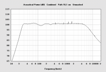
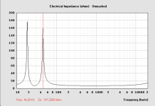
Acoustical Power vs Electrical Impedance

Dear diyAudio,

The question is about Electrical Impedance vs Acoustical Power.

I was able to reach a fairly nice graph for the acoustical power. Then I noticed the worrying behaviour in the electrical impedance. There are two huge peaks, one reaching almost 180 ohms.

What does this mean practically?
Is the Acoustical Power post or pre electrical impedance?
Will there be virtually no sound where the omhs are peaking?
Or, is the impedance accounted for in the acoustical power which would mean I can trust the acoustical power graph?

Many thanks,
Simon

Attachments

  • Skärmavbild 2021-05-07 kl. 16.14.31.png
    Skärmavbild 2021-05-07 kl. 16.14.31.png
    267.5 KB · Views: 246
  • Skärmavbild 2021-05-06 kl. 14.00.30.png
    Skärmavbild 2021-05-06 kl. 14.00.30.png
    287.5 KB · Views: 250

Bookshelf Question..

I wish to integrate loudspeakers into my well filled library/living room. The loudspeakers will be part of the book collection and sitting level with books and 33cm from a back wall.
Hey this is a real bookshelf scenario with real books as the extended baffle, and not some kind of arrangement that "needs a stand".

I like to think think I can forget about baffle step correction here?

I am also thinking about using Dayton RS 150P-8A together with SEAS 27TDFC H1189-06

Really love the transmissionlines I have heard, but the proximity to the wall worries me. Perhaps a sealed or BR arrangement is better?

Any ideas are welcome. I do like to point out the following: I want to stay 2 way, and wish to keep the driver acceleration relatively constant as per (Loudspeaker drive unit cone acceleration - [English]).

This is the reason for drivers above. I also considered the more expensive Peerless/Tymphany DA25 TX00-08.

Any thoughts are welcome!

24” subwoofer box bracing help

Here it goes, my first post on the forum! 👍🏼☺️
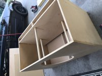
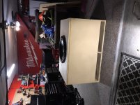
My main question: does the box I built NEED more bracing to avoid a panel blowout? I’m ok with minimal panel flex but I can add more dowel rods to brace sides and front/back panels together.

I finished my 4th box build today. It’s definitely the biggest I’ve done at 28ft^3 gross volume. I enjoyed the process and I am very curious to learn more about building boxes of this magnitude as I have almost zero.

My big concern is bracing. I’ve never used it but I knew I needed to for this build I just didn’t know how much. For sure on the loaded panel to support the weight. But is there a mathematical way to figure out how stiff or rigid the panels should be? I’m currently going to school for mechanical engineering. I have an associate degree so far and almost done with undergrad classes so I can understand almost anything thrown at me no matter how technical. If I don’t get answers I’ll probably search my statics book and see if I can find a solution that I’ll share.

I want to be able to say ok the woofer is this “x” many inches and weights “x” lbs and will it be side/top/wedge mounted. How big is the panel it’s sitting in? What’s the material thickness? What’s the bracing material? Bracing thickness? ... use “this formula” to calculate amount of bracing for opposing panels and “this formula” for adjacent panels.

Not sure if I’m making this harder than it should be? how do you experienced guys do this process without unnecessarily over bracing your big boxes to maximize chamber volume but still keep a tight box that won’t flex or blow out a panel.

I’ll leave some pics of my project attached if anyone’s curious.
Any tips appreciated as I am fairly new to this and I want to learn how to build premium boxes!
This is a finished box but not “finished finished” the guy I built for said he wanted to rhino line on his own.

Attachments

  • 7A6A5E39-69E6-4EE6-8DA0-F32DAE51E02E.jpeg
    7A6A5E39-69E6-4EE6-8DA0-F32DAE51E02E.jpeg
    262.2 KB · Views: 324
  • 2D53B011-2497-4CE2-93DD-05F26C8F4E40.jpeg
    2D53B011-2497-4CE2-93DD-05F26C8F4E40.jpeg
    243.4 KB · Views: 343
  • C6CF93D4-672F-463D-AB72-E32F72EA0650.jpeg
    C6CF93D4-672F-463D-AB72-E32F72EA0650.jpeg
    253.7 KB · Views: 1,994
  • 534834E2-BBF1-44B0-A3C0-78A271754012.jpeg
    534834E2-BBF1-44B0-A3C0-78A271754012.jpeg
    335 KB · Views: 352

Question regarding power tube unbypass cathode resistor

I'd like to build Pete Millett's 6B4G PP amp where he uses 1.5k wirewounds tied to ground per each 6B4G filament connection without bypass capacitors.

It seems to me that for the cathode bias of 6B4G without bypass capacitors, the internal resistance will be increasing to more than 2Kohm. Is there any benefit in doing so, especially in an ouput stage? I know that for the preceeding stage(s) we can use that technique to lower distortion (gain also). I see in other amps that in most of them with cathode bias, they'd use bypass capacitors.

Thanks for your help!

Selling NOS Vintage Electronic Parts

We are a Dutch company specialized in selling (and buying) NOS vintage electronic components.
The range of our NOS products consist of:

- Vacuum tubes (+/- 15,000 in stock)
- Capacitors from WIMA, ERO/ROE, Siemens, Mullard, Kapsch, Philips, Frako, ITT, Spraque etc.
- Carbon Comp and carbon film resistors from Morganite, Vitrohm, Iskra, A&B, Piher, Philips, etc.
- A wide range of transistors & diodes like germanium, japanese, etc.
- Vintage connectors, tube sockets, ic's, audio modules, hifi parts, etc.

Just take a peek at our webshops at:

Home | NOS and NIB parts | NL - Electronic Parts Outlet

or

Instrument Parts Outlet | Reverb

Attention! We have a lot more stuff in stock than we are able to show in our webshop.
If you are looking for something specific, just contact us!

Two populated LM3886-PCBs (open source layout from 00940)

Hi,
in an overenthusiastic moment I built 4 of said boards and ended up only using 2 in my setup. So I´d like to let go of the two spares.

Cleanly populated and all flux removed in a professional ultrasonic bath.
Quickly tested, no substantial DC-offset.
All parts incl. LM3886 are from Security Check.
Will ship in ESD-bags.

Both boards for 25€ plus shipping.

Link to the development thread with schematics etc.:
An open source layout for LM3886?

Attachments

  • PXL_20210605_170402176_cpr.jpg
    PXL_20210605_170402176_cpr.jpg
    394.2 KB · Views: 257

SB17 paper, aluminum or polycone

I'm comparing the following woofers:
6” SB17NRX2C35-4
6" SB17NBAC35-4
6" SB17MFC35-4

does anyone have any experience on what to expect between these different drivers. I can make them all work for my planned 2-way, but I'm not sure on the relative advantages/differences between the cone material.

Could anyone provide some insight into the effects of the different materials. What applications best suit the different materials used in the cone?

Advice on refining SE EL84 pentode Amp

Afternoon all,

Some of you may have been following (or perhaps avoiding😉) my attempts to design and build a SET amp:

Designing a Single-Ended Triode EL34 Power Amp

a project I've shelved for the time being.

Instead, I started a new project building an amp using pentode strapped EL84's and an ECC81 driver. Limited cashflow (and know how) forced the supsension of the previous project, so this one has been done on a strict budget, mainly from spares scavenged from the parts drawer and the darkest recesses of my workshop, where there be spiders...🙂

The only significant outlay was £100 on a pair of Hammond 135ESE's and half as much again in sundries, which represents a considerable saving when compared to the previous project.

I applied power for the first time this afternoon, and was more than a little surprised that not only did it refrain from instantaneous and catastrophic self destruction but also passed a signal remarkably quietly.
Whilst there's still plenty of time for something to go wrong, I'm cautiously optimistic.

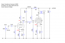
Circuit below, with measured voltages:

Single-Ended Pentode Power Amp.png

I scavenged the mains transformer from an old guitar amp, using a pair of diodes into an EZ81 for hybrid rectification. I've currently tapped the 190V secondary, but may brave it and switch to the 275V winding, although I may have to shuffle things around a little to get the voltages correct.

I'm playing it through my old Mission 752 Freedom speakers, which I'm aware are far from an ideal choice, but it's what I'm stuck with.

Predicatably, the mid-range is more than a little strident (listening to Kraftwerks 'Neon Lights', my wife described the upper register synth sounds as 'lemon for the ears' 🙂).

Any suggestions on ways to tame the mid range would be most welcome. Before I started this whole project, I took the time to post a thread in the speaker forum, where the consensus was that this would happen, so I know I'll need to refine the response of the speakers (the phrase 'you can't polish a t**d' springs to mind).

Is there anything in the circuit I can change to even things out? There's currently no negative feedback, so presumably that could help?

As usual, all suggestions are welcome, and feel free to tell me I'm an idiot for trying. It won't be the first time, or I suspect the last...🙂

Matt.

Power supply design - LF instabilty.

I'm building a class AB2 amp and I have an issue with LF stability. It uses a couple of 6164's in PP AB2, see provisional schematic. Not shown is the PSU. Which consists of an IE core tfmr with a Rpri of 7.5r, and an Rsec of 32r. Vsec is 325v AC RMS into a fuse then a bridge rectifier the into a CLC filter of two 700u caps in series (350u) then a 5H choke, the two more 700u caps in series. All caps have 180k series resistors across them. HT is 410 Load is 2562r as far as I can make out (410v HT/0.160mA) The Idc of 0.160mA is quiescent, I'd expect it to be about 1.5 times that at full whack.I tried adding some small caps in parallel with the 2nd cap, a 10u and a 1u but no improvement. I worked out Xc and XL which is Xc = 454r and Xl = 3140 at 100hz and the PSU source resistance as 45r, but after that am not sure where to go next.

I've looked at all my references and cannot find how to calculate whether a power supply is potentially resonant at LF or how to design for stability or how to fix potential LF instability. I've looked in Radio Designers, Morgan Jones Valve amps, Crowhurst and loads more reference books as well as online.

I tried adding some small caps in parallel with the 2nd cap, a 10u and a 1u but no improvement. I worked out Xc and XL - which is Xc = 454r and Xl = 3140 at 100hz and the PSU source resistance as 45r, but after that am not sure where to go next.

Any ideas welcome. Andy.

Attachments

  • 6164 PP AB2 64kb.jpeg
    6164 PP AB2 64kb.jpeg
    62.6 KB · Views: 318
Projects by fanatics, for fanatics
Get answers and advice for everyone wanting to learn the art of audio.
Join the Community
507,723
Members
7,885,788
Messages

Filter

Forum Statistics

Threads
406,120
Messages
7,885,788
Members
507,723
Latest member
semajbab