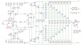
Matrix M400 Mosfet Amplifier

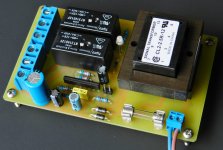
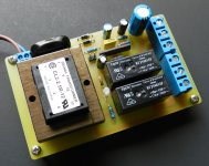
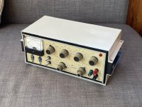
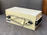
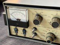
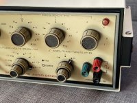
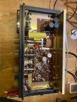
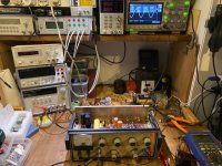
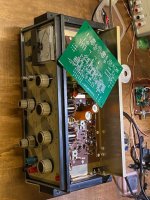
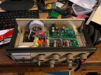
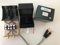
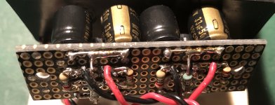
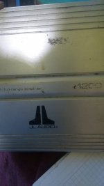
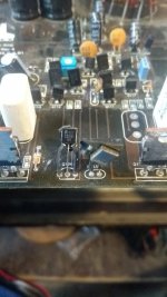
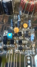
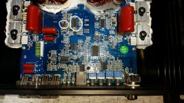
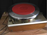
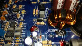
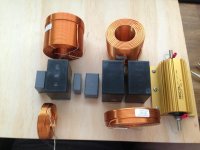
Selling my Matrix M400 Mosfet Bridged Professional Power Amplifier early 1990s. As far as I’m aware these where hand built on request and top quality components installed pics attached of internals.
This is a nice bit of kit with protection circuit and runs only 4 or 8 ohm speakers. If you use any different impedance it will automatically go into protection mode so fully fail safe from damage. Recently changed out all the electrolytics and burnt in over 10 days now using it for around 8 hours plus per day as I also run my TV through it.

Sound is excellent in my opinion and bass response spot on. No loss there.

Reluctant to sell but have too much stuff so starting to downsize.

£120.00 that will include postage within UK mainland.

Attachments

  • 76E57E90-8DB8-4BA4-BC23-2A2ABBB9873F.jpeg
    76E57E90-8DB8-4BA4-BC23-2A2ABBB9873F.jpeg
    215.6 KB · Views: 239
  • DE2C8B30-E661-43B9-99D6-CB875D0299A0.jpg
    DE2C8B30-E661-43B9-99D6-CB875D0299A0.jpg
    737 KB · Views: 244
  • 69FFAF34-4505-425B-AAB3-83144CC58E3A.jpeg
    69FFAF34-4505-425B-AAB3-83144CC58E3A.jpeg
    416.6 KB · Views: 236
  • 438C2ED7-A75A-41C4-A022-F03FF9FC180E.jpeg
    438C2ED7-A75A-41C4-A022-F03FF9FC180E.jpeg
    549.1 KB · Views: 233
  • 39D7E046-3D85-4E7E-A351-E98415BA680C.jpeg
    39D7E046-3D85-4E7E-A351-E98415BA680C.jpeg
    318.5 KB · Views: 253
  • DF4FE600-D104-431F-A24A-76E24D4FF18E.jpeg
    DF4FE600-D104-431F-A24A-76E24D4FF18E.jpeg
    337.3 KB · Views: 178
  • 39B7A514-DF2F-460F-9CF6-D6EC6D8E15AD.jpg
    39B7A514-DF2F-460F-9CF6-D6EC6D8E15AD.jpg
    1 MB · Views: 174

Front loaded horn sub as OB helper sub?

After some playing around with hornresp a front loaded horn sub looks like it might have potential as an OB helper sub.

I have a pair of 10'' SLS-P830668

I tried sealed for the helper sub but didnt like it, it did not integrate well with the OB. Too closed in and restrained sounding compared to the OB, too much undesirable room interaction.
OB subs are ideal but it means a huge baffle and this has too many problems.

I have often heard BLHs being described as dynamic and open sounding,
but a FLH, like sealed and OB, will not have phase issues of the rear ported designs and that seems more appropiate.

The results from hornresp are the surprising part, when aiming for only modest ~50Hz extension the required front horn sizes are a lot smaller than expected, only around 1m.
Im modelling an untapered horn, as you can probably find some sort of piping in the appropiate diameter for this.

I havent found much discussion on FLH subs here (or at least anything explicitly described as a FLH) only on pro sound forums, is there some downsides I'm missing here?
Bandwidth too limited? Still feel like people would work around that if performance was good, like they work around OB limitations.

Viper D2500.1

Working on one of these at the moment.

Currently what it is doing is it seems to work correctly from a cold start up powered through 1 ohm current limiting resistor. It draws ~3.2A which seems about appropriate. I have very low DC offset and good audio signal out. All looks good.

If I shut the amp down with the remote lead and restart it, it draws ~8.5A and I have a little DC offset, ~.450VDC between secondary CT and one output inductor and ~.950VDC on the other output inductor. Relay does not engage but it does not light up the protection LED, the green LED is lit. My power supply sags down several volts.

It does need some time even after I shut down my power supply and try to restart it.

What I have done;

Rebuilt the power supply.
Replaced two banks of five IRF9640 gate resistors were fine.
Replaced one bank of three FB31N20, gate resistors were fine.
Removed both audio driver boards to check for any damaged components and found none suspect even removing the specific drivers to the banks of outputs that failed to verify no leakage. One Ohm resistors are good, the diodes checked OK.

With both audio driver boards out, the amp powered up every time I wanted it to drawing ~1.5A
Verified Rail to Rail.
Verified expected signals and voltages on the LM361.
Found a missing resistor at R168 and installed a 2.2K Ohm one there. R168 connects between the KIA431 and the C1027, see pic.

However, upon typing this, I decided to check the voltage drop on the two Zener diodes that I can easily reach and one of them is out of tolerance (~9.5V) when the amp is working correctly. I am going to look for a replacement, in the meantime is there something else going on that may cause these symptoms?

Attachments

  • 20210525_053811.jpg
    20210525_053811.jpg
    482.9 KB · Views: 117

Pioneer TAD TL-1601A and ATC SM75-150S super

Relisted due to timewaster.

Many high-quality pictures, vids and measurements her Where you can also see feedback from previous sales.e: :

2 Atc Sm75 150s And 4 Tad Tl 1601a For Sale For Sale in Monaghan, Monaghan from /gusss

Here you have two ATC 2 ATC SM75-150S super rare as hen's teeth for £600 the pair. They are £750 each new and even at that - they are not sold as a separate unit. These have been thoroughly tested and are working perfectly as you can see from the graphs using a measurement mic and REW. However, One mounting joint is chipped off on both therefore I am letting them go much cheaper than normal. Price does not include postage or PayPal fees which will be worked out if you are interested depending on where you are based.

Pioneers:

These have been tested working with a multimeter and REW - both frequency and time response is excellent. These drivers are in excellent working condition. One speaker had a dented dust cap which has been corrected (see photo).
Will ship worldwide, Postage cost depends on location and to be worked out when you contact me and price is not including paypal or reverb fees which must be covered by buyer.

Joblot 2 grand individual speaker £510

You will not find a better offer for these drivers online - but if you do, anytime in the last 2 years - I will price match it.

Attachments

  • IMG_20210401_172744.jpg
    IMG_20210401_172744.jpg
    799 KB · Views: 431

Looking for these lights for A&H / GV mixers & switches

In the larger commercial Allen & Heath and Grass Valley mixers, there are loads of square buttons that have little lights inside them. I'm wondering where to get them.

In the past, someone swapped out the red, blue and green lights for yellow ones, probably because they had them in surplus. Now I want to put them back the way they were.

Please let me know if you can point me in the right direction to get them replaced.

Attachments

  • k.jpg
    k.jpg
    556.3 KB · Views: 75

ELROG 3300B Molybdenum Version

we are introducing a molybdenum plate version of the ER300B, called the ER300B-Mo.


Here a feedback from an early user of this tube:

To me the sound of the ER 300B M are again more gripping. More linear. More solid, locked imaging. Better dynamics. More separation.
It feels like the ’transport’ of the sound is more rock solid. It really feels like the same kinda musical step up i experienced going from the my previous set of tubes to the normal ER300B’s.
But now it’s an even more ’solid’ version. The sound signature is the same as the standard ER300B, but everything is much better.
I was listening at the new Tool album, from which is not easy to uncover all the details. It can actually sound very flat on a normal system. With the ER300B M, I finally hear way more separation of frequencies, and as a result it sounds way more ‘grunting’ and ‘gripping’.

Another customer feedback:

They sound spectacular: more of everything, micro detail shimmer on cymbals, bite on trumpets, more nuanced soundstage, bass seems tighten and more defined as well.


I can confirm similar findings in my amplifiers. It is not a subtle difference but immediately noticeable. Of course these new tubes do not render the standard ER300B obsolete. It sill be continued to be offered along these new versions.


Chinese made Kit solid state Amplifiers on Ebay

Hi folks

Just curious has anyone already built any of these kits.
I note their is already a Naim discussion on the site but I was more interested in the L20SE type.
link to finished version here Assembled L20SE Power amplifier board with A1943 C5200 (include 2 channel boards | eBay

I do have previous experience building and modifying equipment and would like to use some of the many vishay bulk foil resistors etc I have left unused.Same with Silmic capacitors. Im not sure I want to try building the Honey badger though it would be a challenge.
Any comments re the design would be helpful.
thanks

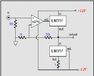
Low dropout adjustable voltage regulator

I’m working on a Taramps 15k amp .

The amp shows no signs of life : no leds lite up no rail or regulated voltages and and the power supply isn’t booting up .

I know that the pic chip needs to see 5 volts in order to operate.

I have 5 volts on pin 1 of the pic chip

I’m wondering if something needs to tell the pic to turn on .

Which leads me back to the LM2941S regulator .

Here are the voltages I get on that regulator not sure if the voltages are correct or not. Anyone know ?

Adjust Pin :1.27

On/off Pin: 0.00 volts when remote is applied. And goes to 6.23 volts when remote is removed

Ground:0.00

In Pin :0.00
Out Pin: 5.13


Wondering if these voltages appear to be correct on this or do I have a problem somewhere

Thick power cables ADD ground loop hum, noise...

From a technical point of view, could or should I expect a thick, heavy (heavy gauge copper, not just a thick jacket) cable to make a minor ground loop hum WORSE than a thinner in-box power cable?

On a few amps, they are best with short, thin basic black cables, but if I add a fancy, thick cable I hear more ground loop hum. Of course, what I am saying there IS some ground loop hum no matter what.

Specifically, there is vastly more copper in the ground wire on the fancy cable (I think it might actually be 2x of the standard 14 gauge conductors)...could that somehow make a minor problem worse?

One of German's most ultimate DAC: Horch "STEPS 1" - Schematic wanted

A friend of medid purchase this device last week in not perfect working condition (distortion at one channel).

Who can upload a schematic or know the type of used DAC chip and operational amplifier IC's for the I/U converter ?

On the web there are not many papers (only in German language) and no test reviews:
HORCH-REFERENZ
http://www.horch-gmbh.de/Produkte/STREAM_A5.pdf

In the attachment you will find some images from internal used PCB's and (very large) capacitors with screw terminals.
There is additional an outdoor power supply, not showed here.

According the PCB's on the photos there are follow IC's in use (unrecognizable resp. defaced - Label was sanded off):
1) Receiver Chip (maybe CS8416 or similar)
2) DAC chip with integrated digitalfilter (covered with copper sheet)
3) operational amplifier for I/U converter and low pass filter

for the reading of file naming, please log out

Thank you.

Attachments

  • Horch DAC model STEPS1.jpg
    Horch DAC model STEPS1.jpg
    63.5 KB · Views: 1,527
  • Horch DAC STEPS1-Top-View-I.jpg
    Horch DAC STEPS1-Top-View-I.jpg
    41.2 KB · Views: 1,548
  • Horch DAC STEPS1-Top-View-II.jpg
    Horch DAC STEPS1-Top-View-II.jpg
    43 KB · Views: 1,517
  • Horch DAC STEPS1-Top-View-III.jpg
    Horch DAC STEPS1-Top-View-III.jpg
    42.7 KB · Views: 1,534
  • Horch DAC STEPS1-Top-View-IV.jpg
    Horch DAC STEPS1-Top-View-IV.jpg
    40.4 KB · Views: 1,483
  • Horch DAC STEPS1-IU.jpg
    Horch DAC STEPS1-IU.jpg
    40.7 KB · Views: 812
  • Horch DAC STEPS1-Filter.jpg
    Horch DAC STEPS1-Filter.jpg
    43.2 KB · Views: 798
  • Horch DAC STEPS1- SPDIF-input-DAC.jpg
    Horch DAC STEPS1- SPDIF-input-DAC.jpg
    40 KB · Views: 822
  • Horch DAC STEPS1-input-selector.jpg
    Horch DAC STEPS1-input-selector.jpg
    33 KB · Views: 788
  • Horch DAC STEPS1-Capacitors.jpg
    Horch DAC STEPS1-Capacitors.jpg
    45.2 KB · Views: 806

Home backyards picture for PA full range

Hello,

I am getting a three way (1x) Jbl Prx 818xlf subwoofer + (1x) Jbl Prx 812 Speaker to make small parties in my home and for self enjoyment sound.

PANO-20210613-155654-vr — ImgBB
Photo (panorama): my backyards

If you scream loud, there is an fast echo. But not much.
There is slapback behind the speaker coming from the house building, but can only be noticed behind the speaker.

How can I optimozate the audio experience in home backyars?
Maybe adding more speakers? Maybe wall treatment? Panel difusors?

Please leave your opinion will help me a lot and feel free to share your backyards

DIY Nixie Tube Display for turntable tachometer

This is a shared DIY project for non-commercial use.

This project is an extension of the DIY Arduino tachometer; several users have requested a Nixie tube display as an alternate to the LCD. There are currently two versions of the Nixie display, using IN12 tubes and IN16. I've included the EagleWare .brd file if someone wants to modify it for use with other Nixie tube types.

The PCB uses all thru-hole components for easy assembly, but some soldering skills are still required. The uP is a DIP package but there is a socket for it on the board.

The project consists of a bare PCB, a parts "kit" available as a shared cart from Digikey electronics, a uP with the operating system pre-programmed into it and the on-line documentation you see here. The two PCBs are identical except for the display tubes, so the shared Digikey cart works for either build. It is highly recommended to use socket pins for mounting the IN12 tubes, which are not included in the Digikey shared cart. You must add them to your order. The Digikey PN for the pins is ED90326-ND; you will need at least 60 pcs (12 pins per tube). The IN16 tubes do not (and cannot) use sockets, they are soldered to the PCB.

The PCBs are available from OshPark PCB fabricators at the following links:
IN12: OSH Park ~
IN16: OSH Park ~
The PCB is created in multiples of 3 for a cost of ~$97.66 or $32.55/board.

The PCBs are available from PCBWay fabricators in China at the following links:
IN12: Nixie Tube Tachometer Display for IN12 type tubes - Share Project - PCBWay
IN16: Nixie Tube Tachometer Display for IN16 type tubes - Share Project - PCBWay
The PCB is created in multiples of 5 for a cost of ~$54 or $11/board.

The parts kit can be ordered from Digikey Electronics: Digi-Key - Fast Add
The parts kit to build 1 PCB costs $45.87. If you are using IN12 type Nixie tubes, it is highly recommended to add 60 pcs of ED90326-ND socket pins to make inserting and removing the tubes easier.

The pre-programmed uP is available in the US from DIYAudio member Seth Hensel via PM. Cost to US (shipping included): $13.

The pre-programmed uP is available in the EU and RotW from DIYAudio member Scobham via PM. Cost to UK (shipping included):£10. EU:£12.50 RotW: Depends on destination (Ask).

IN12 and IN16 Nixie tubes and the HV power supply are available from http://www.shop-tes.com. If ordering IN12 tubes, you must have at least one type IN12B which has a decimal point (middle tube on display); the other 4 can be IN12A (w/o decimal) or IN12B. There is only one version of the IN16 tube with decimal points. The HV power supply is type 1364 Horizontal.

The following documentation is available below to aid in construction of the project; the files are grouped into a zip file for each version (IN12.zip and IN16.zip) and a third file (Eagle.zip) has the necessary .brd, .lbr, & .cam files to modify the layout for other tube types.

INxx PCB.pdf
INxx Parts Locator.pdf
INxx Schematic.pdf
INxx BOM.pdf (Generic bill of materials with part references)
INxx Instructions.pdf
INxx Gerbers (folder with RS274X Gerber files if you want to use your own board house).
Eagle.zip (IN12 tach.brd, IN16 tach.brd, Nixie.lbr, IN12.DRL and NIXIE_IN12.cam Eagleware files to modify layout for other tube types).

Attachments

Adcom GFA-555 High DC Offset Question?

Hi all,


I'm relatively a new member and forum lurker and have generally found answers to my questions by simply searching the respective boards, but haven't found a specific thread that addresses this problem directly and specifically to my issue.


Here's the question?


I have an Adcom GFA-555 that I'm trying to figure where to start with a high DC-offset.


Both speaker output channels are reading about 8.23 & 8.35 vdc.


Not the 82.00 vdc I see in most of the threads I've searched.


Anybody have any pointers in directing me to where to start and what to look for first.


I have an oscilloscope and DMM.


And yes I understand about the high voltages and current.


TIA

LCR phono stage with cascode input - any obvious improvements?

Recently finished putting together an LCR phono stage as per the attached schematic, apart from the CCS for the second stage being a 10M45 run from the full B+ rather than reduced amount(haven't got round to sorting out a setting for that on my LTSpice).

The input stage is an ECC88 cascode with the output impedance used to match the LCR network. Given that there is more gain than I need and given that the load resistor needs to stay as it is to keep the frequency response right, are there any obvious changes? The things I am pondering are LED bias of the first stage (it is set up for 2.5V with the resistor as it is) or possibly having only a partial bypass of the cathode resistor (say 220ohm bypassed with 110ohm unbypassed to add a little local feedback) as the schematic appears to give 1.5V out for 5mv/1kHz which is pretty huge. Would these be worth looking at, and is there anything else people would suggest?
As a background, the project was to have a look at what an LCR stage would be if it was made to fit in with the World Designs valve kits.

Attachments

World's Best DAC's

Let's continue the popular series ''World's Best'' that so many people love and hate 😛


So, this week: Digital to Analog Converters ... DAC

I'm more of a Speakers kind of guy, no so much into electronics; amps, preamp, source, etc... BUT i do feel the DAC part to be of great importance in a sound system.

So, let's discuss about the best DACs you ever heard (and hopefully side-to-side compared)

To this day, my references are the dCS. And i really, really hope i'll find some cheaper solution, 'cuz i need 4 of 'em... 😕


***** UPDATE 26th OCTOBER 2016 *****

Started to test and compare Digital-to-Analog converters, and note each of them in my particular context (active speakers so each way at a time).

Tested so far (in my own system):

Fiio D03K:
3.2/10 in general

Grant Fidelity DAC-09:
2.5/10 on highs+ 4.3/10 on mids

miniDSP 4x10HD:
3.8/10 in general

Moon Neo 280D:
3.5/10 in general

Marantz DAC-HD1:
6.2/10 on highs + 5.8/10 on mids

DEQX HDP-3:
5.9/10 on highs + 7.8/10 on mids

NAD M51:
7.4/10 on highs + 6.8/10 on mids

Gustard X20:
8.0/10 on highs + 7.5/10 on mids

Weiss DAC2:
6.3/10 on highs + 6.6/10 on mids

Weiss DAC1 mk3:
9.1/10 on highs + 8.4/10 on mids

Forssell MADA-2a:
9.5/10 on highs + 9.2/10 on mids


As of today 26th december 2016, the Forssell is the best Digital to Analog converter i have heard, followed by the excellent but more expensive Weiss DAC1 mk3 and the affordable but unreliable Gustard X20.

RF T1000-1bd

Hi!

Comes to me a rf t1000-1bd, sometimes plays with a lot of distortion and sometimes turn on the orange protect light.

Someone try to fix it before me, so i dont know if the replaced components are ok. I dont have the schematic.

I need a clear picture of the output area, the components replaced are
Q2003, Q2005, Q2002, Q2004, Q2016, Q2018, Q2017, Q2019.

Thanks

Attachments

  • 20210612_185142.jpg
    20210612_185142.jpg
    797 KB · Views: 113

Non standard Schematic symbols

A thing I truly hate, when one uses obscure, antique or just plain "made up" symbols in schematics. Stop people, don't just pull this outta your behind.
This one I'm likely going to build, but before I head off stateside (One month)...I have to decipher the non-standard symbols...for the handful of parts.

Now, we have three variations
like 11K=8X22K 470K//470K

3X2.7K

I'm guessing the 11K is the final value AFTER arranging eight 22Ks
the 470K//470K LOOKS like a pair of 470 in parallel for 235K ohms
The "three times 2700 ohm" third variation, I have no idea.


-----------------------------------------------------------------------------Rick....

Attachments

  • 2A3 parallel single ended.jpg
    2A3 parallel single ended.jpg
    48 KB · Views: 260

TGM6 - modified Pioneer HT amplifier

A few weeks ago I pulled an old Pioneer amp out of the garbage. I pulled out all the boards except the amp and power supply, pulled out all the controls and junk off the front panel.

I was initially intrigued by the amplifier design, it has a lot in common with my first project, the TGM (TGM1) amplifier - http://www.diyaudio.com/forums/solid-state/226482-pioneer-vsx1020-like-tgm1.html

After taking some time to find my around the schematics I was able to get it powered up. With most of the boards scrapped I had to install some jumpers, fix up the grounding scheme, enable the output speaker relays and wire in a temporary volume control on one of the channels.

The original amp was set up with a design target of 2mV across the output emitter resistors. Being a fan of D. Self I adopted the more acceptable target of closer to 25mV.

I didn't want to waste any more time until I'd heard it so I decided today to fire it up. And now that I've heard it, I think it has potential and so I'll be spending a bit more time on this design.

For my initial test I used a PMC speaker, a Sony blu-ray player and a YBA CD player for source material (Pink Floyd Animals and Christy Baron).

Initially I got some hum in the speaker and wondered if my earthing scheme was messed up but it was eliminated by powering off my nearby TGM5 amplifier; the TGM5 has a power supply that leaks flux like nobody's business.

The sound was cleaner from the YBA than from the Sony player. I used my Bryston BP60 amp as a reference amp, with the left channel from the source playing through the Pioneer amplifier and the right channel playing through the Bryston amplifier. The difference between them was not very significant - in fact I was a bit surprised by how good the Pioneer sounded. Ultimately the Bryston sounded cleaner, but the Pioneer amp lost little in terms of bass, treble and overall dynamics. It did have big power on/off thumps though due to how I've set up the power to speaker output relays (speaker protection is enabled and I tested it beforehand using a d.c. source).

So I will do some more cleaning up and consider some further modifications to see if this can become my next generation, "TGM6", amplifier.

The attached image shows the TGM6 making it's first sound. I've used one of the original pcb's from the amp as a platform to provide RCA inputs and a convenient connection to the amplifier inputs. There's no power to this pcb and so the parts on it are non-functional. I removed some coupling capacitors to provide convenient through-holes to install the blue coloured Cat5 cables you can see. These cables run to the front panel and provide connection for a passive volume control pot (50k Ohm). Sitting inside and on the bottom of the chasis is the power supply pcb along with the output speaker protection relays. You can't see the amplifier pcb here, just the tip of the back of the amplifier but you can see the fins from the heatsink.

EDIT: 25 Jan 2015> TGM6 Reloaded: http://www.diyaudio.com/forums/solid-state/230403-tgm6-amplifier-7-channels.html#post4199133 (post 13)

member 'GrQ' on TGM6.2: "The amp is fine, i keep it at my friend home for usual gathering, remind us about hard working overtime doing this handmade amp lol."

Attachments

  • first sound.JPG
    first sound.JPG
    440.5 KB · Views: 1,173

CX900mk2 PCB for sale!

There are still 4 sets of PCBs for sale with which you can create / upgrade the Fantom CX900 audio amplifier in the new CX900mk2, as in the following topic:
Modernizare Fantom CX900 - Modernizari / reconditionari aparatura electronica - Portalul Tehnium Azi

For the modernization or development of the new Fantom CX900mk2 I developed two personal projects:
1. DP0154 (audio amplifier);
2. DP0812 (230VAC softstart for transformer & auxiliary sources for the new CX900mk2).

The DP0154 project is based on two PCBs: left and right, which are based on the same electronic schematic. The DP0154 project is in PDF format and will be delivered after the purchase of the PCB set presented below.
In general, the DP0154 design is built around transistors MJ15024 / 15025 (also four pairs of transistors per channel). An operational amplifier such as OPA134PA or LME49710 is used on the input side. And a PCB Left (or Right) has three supply voltages:
+/- 50 ... + / - 80Vdc (amplification stage supply);
+/- 15Vdc (power supply preamp section) and
+ 24Vdc for the protection / delay part, connection of acoustic enclosures, with relay.
A PCB DP0154 (CX900mk2) contains all the necessary circuits, including DC protection of the speakers, delay connection of the speakers, limitation of the output current through the final transistors,
input gain operational amplifier with adjustable gain to adjust the input sensitivity of the whole PCB etc.

The DP0812 project is a free project that I have attached below and is part of the collection of personal projects that can be accessed here:
"donpetru" projects - Portalul Tehnium Azi

So, a PCB set consists of:
1 piece PCB left - DP0154 (CX900mk2);
1 piece PCB right - DP0154 (CX900mk2);
1 piece PCB DP0812
4 pieces of aluminum radiator (L profile, 50x30mm, 5 mm thick). So, you will have to drill these heatsinks and attach them to a larger heatsink. In the project documentation DP0154 there is a page with a template to help you with this operation.

A PCB set costs 30 Euros and transport by national mail costs about 15 Euros, for sending to European Union countries. For other countries or locations, please contact me to communicate the exact shipping price.
Payment will be made in advance via paypal to an address that will be communicated by private messaging. So, please ask me!

It is a project that should not be missing from the library of any audiophile.

I have attached some images with these PCBs and with the project in PDF format DP0812. I repeat, the other DP0154 project will be delivered after the purchase of at least one set of PCBs like the one in the images presented below (I presented an image with the top side and one with the bottom side).

Attachments

5xG300 class-d amps (10 ch) sinewave

Never used 4 working sinewave modules, plus one module for parts G300 v.3 with all necessary wires (based on Tas5630)
These are high-end modules without caps in signal path (with dc servos)
$240 for all 5 (this is 1/3 of what was paid)

Specifications
Power:90-265Vac 50 or 60Hz
Load: 2ohm/4ohm/8ohm
Max Output Power: 300W/4ohm or 150W/8ohm or 300W/2ohm 10%THD+N
Output Power: 2x150W 1% THD 4Ω (in stereo mode)
Output Power: 2x250W 4% THD 4Ω (both channels in parallel)
THD+N = 0.003% @ 1W (4Ω,1kHz)
85 % total efficiency @ 100W output
Input sensitivity: -10dB/100kohm
Frequency response: 20Hz-30KHz +/-1dB@10W

Features
Regulated auxiliary power supply
Thermal protection
Over current protection
Soft clipping
EMI conforms to: EN55013 EN55020 EN61000-3-2 EN61000-3-3


purchased from 正弦波电子
details are here: TAS5630 + SMPS modules for sale

Attachments

  • G300 v3 dc servo.jpg
    G300 v3 dc servo.jpg
    350.8 KB · Views: 475

One amp channel roars for a few seconds when switched on. Soldering iron ready...

I have a few Behringer A500 power amps. Channel 1 in one of them roars for several seconds when it's switched on before settling down. I think I've also heard intermittent clicks/pops.

I'm nervous of driving my active speakers with this as something is clearly wrong. I have a little experience with a soldering iron and physics, but I'm pretty ignorant about the details of amplifier electronics.

What is likely to have gone wrong, and how can I find it with my 'SMART^2' multimeter? I've had the amp open but couldn't see anything obviously burnt. Any chance of a little kindly guidance? Thanks in advance...

ESS9018 - try new, try more...

I think to start this new thread based on my own recent experience with this ultimate DAC.

I intended in the last time to change the ESS9018 clock oscillator, but I had not at that moment a right one. So I used an 106 Mhz for that max clock frequency specified in datasheet (100 Mhz).
It was accepted very well by ESS9018...
So, afterwords I`ve tried more. I bought one of 125Mhz and one 150Mhz. It was OK with 125Mhz, but didn`t work with 150 Mhz. So, my conclusion was that the limit have to be in this range (125 - 150 Mhz).
Recently I`ve tried with an 133,3 Mhz. It worked!
I have to say that the result of those experiments have been appreciate only perceptual, without very close measurements or any deeper analyses of what is possible to happen inside the chip at this high clock frequency. I had not that time to get closer/deeper in to this. I used both FLAC files and SACD/DSD. Even on ordinary CDs (44,1 khz sampling), the sound is fantastic The resulting sound after this upgrade is just exceptional in details. I never heard a such deeper and sophisticated bass, and the sound stage is amazing, comparing with an 100Mhz clock.
I can not say that ESS9018 it sounds not well with an 100Mhz clock. It could be stupid to state like this. But is a perceptual positive result after changing to a higher clock frequency. The details increasing in the sound is easy to notice.

By the way, my experiment object/DAC is not an very impressive one as design... I had not yet a Buffalo 3 PCB design at the experiment moment... But anyway this one it`s work very well after the modifications one can see in the picture. I think to take a look more seriously on this subject based on a Buffalo mounted ESS9018.

The point is now to share this experience, and invite you to come with your comments, impressions and even a closer look in to this field.

Attachments

  • IMAG0456b.jpg
    IMAG0456b.jpg
    358 KB · Views: 4,318

Need Advice - DIY HT Sub

I’d appreciate some advice for where to find a HT sub design that would fit my goals.

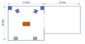
I have a family room that is approximately 16’ x 22’ with 9’ foot ceilings (3,200 cu ft), and next to it is a game room that is 12’ x 15’ (1,600 cu ft). The rooms are largely open to each other. In the family room there was at one time a fully built-in large projection TV enclosed with drywall and cabinetry on either side, so I have a space that is 48”W x 30”D x 52”H which is largely open for a sub, just a flatscreen in the front of it with 15” below the TV for a sub to project although behind the flat screen much of the volume is empty. This location is also in a corner of the room and projects back to the opposite corner and also into the game room.

The area that’s exposed under the TV (will be covered with audio cloth) is approximately 15”H x 40”W if leaving room for trim, the actual sub box sitting behind the trim could be higher.

I’m looking for a solution that is weighted towards sound quality (movie sound tracks, online concerts) but want enough bass to make action movies exciting, but don’t need to blow out windows. For this reason I’m leaning towards an closed sub (also simpler to build).

I’m thinking a 12 – 13” driver (or larger?) and am willing to spend up towards $800 all in (driver, box, power amp). The rest of the system has small bookshelf mains (Paradigm reference 20s), center, surrounds etc.

My questions are:
1. Is there a ready-made design that would work
2. What are driver recommendations
3. What are amp recommendations
4. Is there a concern having the sub somewhat enclosed on the sides and top will affect the sound quality (there is a fair amount of air movement through the wide cloth grill and around the TV)
5. If the driver is 12 or 13” and the opening between horizontal wood trim is 15”, is this sufficient for the driver to properly project without interference.
6. Your thoughts on the cost/benefit of building two units (each cheaper than $800) and having a second sub behind the listening sweet spot.

Really appreciate insights from better minds than mine.

Thanks!

Seas 27tdfc, seas ca18rly - crossover thread

Hello everybody. I wanted to know if anyone in his diy project used seas 27tdfc and seas ca18rly (or similar) as speakers. in fact, I wanted to compare on the type of crossover you used. my crossover is composed as follows:

Tweeter: series 4.7ohm-8.2uF. Parallel 0.150mH
Midwoofer: series 2,4mH. Parallel 12uF-1ohm.

thanks to those who want to participate!

Omtec Mono Power Amplifier "CA 25" (CA25) - Schematic wanted

Omtec Mono Power Amplifier "CA-25"/"CA-60" (CA25/CA60) - Schematic wanted

For this mono block device I need a schematic diagram. There isn't a download aera for PDF schematics. Only for the Owner's Manuals of all models
Bedienungsanleitungen
and I have heard, that no schematic would be released (like Krell Industries).
So I must hope, one of the members have an own created schematic
If so, please let me know - thank you very much

Attachments

  • Omtec CA25 front+top.jpg
    Omtec CA25 front+top.jpg
    35.7 KB · Views: 1,369

When do you feel the golden era of HT gear was (if in the past)?

Obviously we have better picture, sound, and access to content - so from a technical point of view, each passing day is the new 'best ever'. Today, for $5,000 I could buy a 75-85" TV (or very nice projector), nice receiver, great speakers, all the accessories, and still have money left over for every streaming service and a huge stack of 4k discs.

However, from a personal and emotional point of view, the early DVD era was the golden age for me. Few reasons:
--This is when I was coming of age into this world, and I certainly look at it fondly
--True discreet surround sound as standard, a huge step up from Pro Logic
--Easier to setup a HT system in terms of the speaker configurations (5.1 and you were done)
--Larger (better sounding) speakers were common and acceptable
--There was a ton of consumer demand across the price bands, and every audio company was all-in on HT gear
--Because audio and video was still 'simple' and didn't change often, you actually had many of the high-end brands able to make HT receivers or preamps. Much less common now days.
--There was still some 'magic' with analog video in terms of a high-end DVD player, or if you were rich, offboard processor giving you a better picture.
--None of the HDMI gremlins or copy protection issues (if you plugged it in, it worked)

Of course, tons of bad things. 480p video, small TVs (or VERY expensive), no streaming, content was expensive and hard to get in some cases (DVDs), still needed to have an expensive cable or satellite package, etc.

All that said, the Blu-ray era (once HD-DVD died) was great. Even by todays standard, Blu-ray looks excellent and you had better sound. However, it also started the beginning of the end of simple HT gear which pushed most of the selection into mass-market gear...and soundbars...which started to kill off HT gear in general. People traded sound quality for the convenience and design.

bit of advice putting a screw back

sorry if the headings a bit, well basic, but this is precisely the issue.
Ive been putting back together a NAD 3020E and all was going well up to about 2pm, and i had it on test for a few hours before this without any issues.
then i suddenly realised i hadnt put the grounding bar back in that ties the case to the main board.
so when i went to put it back in i got to the last screw(photos) and it was sparking like mad.Now a screw came out of there this morning, and i havent realy done very much to this unit other than check it over and correct the idle/centre voltages which were way out as it happens.But the amp was working fine.
when i checked it after the sparking episode and plugged it in with the lamp tester, it was😱 the lamp lit up like blackpool.So 2 blown fuse (T4A x2).so back to the testing.wittled it down to a possible dry on the rectifier.
plugged it back in and all good but......little sparky screw is still there, so the question is, why is it sparking, should the screw be sleeved through the heat sink(it wasnt originaly) or should i leave it out,i dont think i should but what do you think?
the amp currently has no faults other than Mr sparky screw

Attachments

  • IMG_20210612_171543.jpg
    IMG_20210612_171543.jpg
    272.6 KB · Views: 167
  • IMG_20210612_171600.jpg
    IMG_20210612_171600.jpg
    238 KB · Views: 185

Hi from Brisbane

Hi,

I have been a member for many years and thought it was about time I added an introduction!

I was introduced to diy by a late friend who was kind enough to build me a pair of Aleph 2's (my Aleph 3 was too small to power my Magnepan MG3A's properly). Around the same time he also built an Aleph P1.7 for me, but never got it working.

I had no experience with electronics and being busy with work and it took me some time to try if I could do it myself. It turned out the soldering (of through hole parts) was easy to master (desoldering is another story ...) and I built an O2 headphone amp, followed by a DAC designed by Spencer (fetaudio.com).

I pride myself on debugging the Aleph P1.7 my friend was unable to complete. It worked, but I had some trouble with the Dantimax volume control, designed an arduino controlled replacement but I never finished it and sadly the preamp is on the "will fix this one day" pile.

Over time the number of projects grew, but most remained in the "nearly finished" phase. I did finish an Aleph J and a J2 (using original Semisouth parts I bought years earlier for an F6 that was never built), but many others are still waiting to be built or partially finished.

I retired some years ago and have moved back to Australia (Caboolture, Brisbane northside). I now have the space and time but physically it is becoming more and more difficult. Soldering PCB's is not difficult (and I think my soldering is actually pretty good), but as a wheelchair and vent user the task of wiring and installing boards, transformers, etc. in a case is impossible without help. So, for now, I have many projects that are waiting to be finished. Not that this discourages me from buying parts haha.

To kickstart me back to my hobby, I entered Nelson's VFET lottery and to my surprise was one of the lucky people who were able to buy one. Mine is nearly finished, just the final assembly left to do.

If there is anyone in the area who would like to give me a hand with some of the projects, you are more than welcome to come over. Besides pre, power and headphone power amps, some other projects are waiting to be started or finished. I have a decent set of tools, both an analog and digital scope, an old Fluke 45 benchmeter, a Fluke handheld meter and various other measuring equipment I collected over the years.

Toshiba XR-Z90 - Any info?

Hi All, not been here for a while.

I picked up one of these players from a thrift store today for £20, and it sounds pretty decent (relatively speaking) a bit sharp on the top end, but a nice weighty bass 🙂

I know next to nothing about this unit, apart from it being 'rare', originally costing 255,000 Japanese Yen, is a vertical loader and that it was manufactured in 1983...

If anyone has any info regarding the chipset for this unit, that'd be great 😀

(I probably won't keep hold of it for long, seems that there is a market for these, one for sale at the moment for €599 / £317!!)

After a decade of planning, thanks to forum members

Thanks in particular to Earl Geddes, BButterfield and FoLLgoTT, also to several people who've posted about MEH designs, though ultimately I could not find an MEH that suits.

For a decade GedLee Harper speakers were my mains, with various (sub-)woofers. This arrangement gave years of pleasure - thanks to Earl, twice over. I bought the Harpers as the Abbeys and Summas were beyond my reach, with a plan of later upgrading to larger GedLee speakers (bad plan as it turned out).

Background: I use a computer for playback, and am content with running convolution filters for crossovers, and very limited room correction at LF, etc., and am familiar with relevant theory (physicist). I also have DCX2496s. I agree with Earl Geddes about the trouble arising from trying to fix acoustic problems electronically.

I've considered options to replace the Harpers to obtain directivity control down to lower frequency, i.e., an extra octave roughly, as Summas would have yielded. I've also considerd narrower vertical directivity to avoid floor and ceiling reflections in my relatively low-ceiling room. That these qualities are not essential allowed me to be content with the Harpers. Designs and ideas that I considered include large conical MEHs; Taipuu-like large-fronted co-ax speakers; Grimm LS-1 shaped speakers, but with a "more-coaxial" layout; and various arrays. For some of these ideas I built prototypes or test baffles, including some MEH before I got the Harpers.

I rejected conventional co-ax designs due to throat problems - I tried a few experiments at correcting reflections in an old B&C drive - not bad, but really hard to get better than the Harpers (measurement or listening) and it would really need to be a 15" or a coax with an array of other emitters round it. I wonder if I ever hear the Taipuu speakers or similar will I be surprised?

My attempts at conical MEH were killed by what I later came to understand as HOMs. My conclusion was that throats must be OS, and ports are tricky. I considered learning 3D printing for a throat section, but rejected that, and I cannot find any commercial waveguide solution to modify.

I'm not sure a waveguide solution is possible, given the desire for vertical directivity - "pattern flip" is unacceptable which rules out almost everything, except a very few options e.g. XT1464, which is rather narrow horizontally ... Moving to a house with higher ceilings, and fitting modifiers is out of the question.

Progress picked-up when Horbach-Keele arrays came to my attention, and shortly after that FoLLgoTTs excellent design
Pseudo-coaxial with narrow directivity (and Horbach-Keele filters)

Fortunately, I read (enough) German and spent a while considering and simulating this approach. My new speakers benefit hugely from that. I was, however, unsatisfied with the side-woofer idea, and general box shape, having convinced myself that wide baffles should work better, and could never quite find the right solution.

I was circling around this when I first read BButterfield's thread* Fractal Array Straight CBT with Passive XOs and no EQ and this immediately started to open up opportunities, though again the final speakers are not copies of his "prototype" described elsewhere (not linked on this site by him for some reason, so I won't do so either, but not too hard to find), even if at a quick glance they look quite similar.

I desgined and built wedge-shaped speakers: 172cm (h), 66cm (w). The wedge is from about 6 to 14cm deep, with the outer edge larger and rounded. The driver layout is more symmetrical than BButterfield's design with the "centres of mass" of the tweeter, and upper-mid and lower-mid arrays aligned (co-axial, though that's a minor tweak indeed). I also put all the voice-coils in a plane.

The tweeters are AMTPRO-4 in waveguides not unlike FoLLgoTT's, but made from wood filled with modelling "clay" (DAS) using a crude custom shaper, not CNC. The AMT has a highly damped rear enclosure.

The six upper-mids are Peerless TC7FT04-04. They sit behind holes in the baffle that forn low-pass acoustic filters. With a bit of DCX2496 correction, these filters dominate the crossover. The Peerless drives are more sensitive than FoLLgoTT's choice, and were readily available. I went for an asymmetrical layout (three not four pairs - somewhere between the two sources of inspiration). There's a complicated box enclosing the upper-mids and the AMT enclosure. This is also braced to the back (with some lossy compliance for damping).

There are six Peerless FSL-0512R01-08 distributed according to the "fractal array" principle, taking up most of the baffle height. These are conventionally flush-mounted, and the baffle thickness of 30mm puts all 13 voicecoils in a plane. I did not add the extra mid-bass drivers right at the foot of the baffle, as seen in BButterfield's solution, but then was not aiming for as low a cutoff frequency. The main volume is connected, with a bit of lossy-bracing here and there.

I already had separate 12" woofers (old Precision Devices PD12SB30) to go with the Harpers, and these are now repurposed in sufficiently-shallow boxes that sit against the wall just "outside" the main speakers (which sit tight against the wall). The mains are about 1.5m from side walls and about 3.5m apart.

In terms of min-phase filters and delays, a DCX is used to tweak the various subs and woofers and another is for the crossovers. The four (sub-)woofers basically run flat, with some small delays/phase adjustments, most of the work was in finding the right places to put them. So, ignoring detail below 100Hz - entirely room dependent, the crossovers are at 130Hz, 800Hz and 2.8kHz, inspired from the BButterfield arrangement (i.e., min-phase filters for min-phase drivers, with very little EQ). The directivity is intended to be gone by about 250Hz where the array is one wave tall tapering to up to the narrow vertical CD by no more than 750Hz.

I'm still working on minor tweaks of the crossovers while looking at lobes and reflections (my target is 10dB down for anything at all bad radiated over any important range of angles as measured at the listening zone). I am not disclosing them in detail as that would be pointless. Almost all the information that would be needed is given by BButterfield in any case.

Based on impulse measurements, the result meets my goals, at least broadly. Initial measurements suggest that floor and ceiling reflections are reduced by about 10dB at least in the upper-vocal frequency range and above. Side-wall reflections are delayed over 3m and look relatively neutral (measurements continuing). That's not as much delay as with the Harpers, but the directivity is controlled to lower frequency so the reflection is cleaner over the band. The response on/near the listening axis is as desired, without unjustified corrections - there's a min-phase notch for the Helmholtz resonators on the upper mids and some gentle correction of the AMTs above 8 kHz, that's all so far.

The speakers are driven actively in the four bands, with the drives wired in sets to achieve impedance of 3-5 ohms for each input (three parallel pairs, two parallel triples and the tweeter). Consideration of voicecoil thermal mass was important for low compression, even though these very sensitive speakers won't ever be fed much power at all, I was scared to lose the benefits of the B&C drives in the Harpers - six 91dB (1W) drives with 1.2" VCs should do well enough above 130Hz (drives working coherently): more thanks to Earl.

For completeness, there are two 12" woofers, a 12" subwoofer (commercial BK Electronics) and a 3m long 15" closed subwoofer with built-in Helmholtz resonant low-pass filter (kills high order HD). That started as a tapped horn, but I could not brace it well enough to kill a couple of bad resonances on harmonics that were audible at times.

The Harpers now take surround duties in the rear room corners, used for a few suitable recordings (20-30m delay seems reasonably convincing with old church/cathedral sounds, for example). The main amplification comes from Hypex UcD (a mix of 180W and 30W) and a couple of other cheap class D chips for the surrounds and 15" sub.

It astonished me that, after only a little refinement, the tonal impression was rather similar to the Harpers, differences are mainly in the "imaging" - that's so recording dependent that I won't even try to describe it, beyond saying that many recordings work better and a few definitely don't! As measurements suggest, there's less "room" with most recordings. Further comment would be pointless, but I agree with some of the impressions recorded by BButterfield and friends, elsewhere.

If this (rather long) post, is seen by those whom I thank, I'll be more than happy. If it inspires someone else to follow their ideas and have as much fun, and some frustration struggling to find the right design, that's a bonus.

I won't post in-room measurements (need too much interpretation), and these speakers won't be moving outside, ever. I won't post crossover details, at least until I've done very many more measurements. I'm spending too much time listening to music for that to be any time soon.

I kept a couple of alternative designs in reserve, but these don't fit with BButterfield's suggestion - to avoid reflections from the rear (aka front) wall: "baffles should be much wider than the front is from the wall behind", so unless I start a wall-building project, that's the end for a while.

Ken

*apologies for the error in this URL as originally posted. I hope now corrected.

Yamaha YP-D71 external PSU

I am in a process of restoring this Yamaha TT and thinking about moving PSU and most importantly the transformer outside of the deck. I've done it in the SL-1200 according to the thread here and I liked the result.

Any suggestions recommendation on what would be the best way to do it here? The schematics is attached. I am planing on using two LM-based regulators, but have some concerns about the second tap, if I get enough regulated voltage...

Would appreciate any suggestions.

Attachments

Op-amp input impedance when unpowered

Hello all,

I was wondering what the input impedance of an op-amp like LM4562 would be, in the absence of a power supply (0V). My wild guess is that it would still be high (not sure though), as the input stage biasing would be lost, deactivating the differential pair, muting the amplifier. Please correct me if you think I'm wrong.

The basis for the question is the idea of a simple attenuation ON/OFF switch that would short out the power supply of an inverting attenuator (using MOSFET/relay etc.), to turn off the attenuation (picture). After removal of power, the signal path to the next stage (power amp) is expected to be retained through the resistors Ri and Rf.

Please note that I would like to avoid using controls / switches or digital attenuation for varying the gain, as the number of channels is just too many (16). Looking forward to reading your comments. Thank you.

DSC_0020.jpg

Karlson's Fig. 6 Curved Reflector - who here is good at ray tracing ?

Karlson's patent 3540544 noted possible improvements to Karlson's original cabinets by use of curved reflectors Fig.6 & Fig.8.

Below is a side view of the "SK6.5" cabinet for fullrange 6 inch speakers. It was derived from a working larger version.

If any reader has time to draw some lines then that would be nice to upload.

If Akabak3 can truly handle the reflector and slot from a 3D model, then a simulation should be interesting.

YIz8Ekn.jpg

FS F6 TOTAL Parts NEW

FOR SALE $250 +shipping

F6 PCB Pair of mirrored F6 PCBs and 2 Jensen JT-123-FLPCH signal transformers The boards are fully stuffed including J fets purchased at this store also comes with Antec 4218 Transformer and Universal Power Supply with NEW parts. All parts are New never used TOP OF THE LINE from DigIkey or Mouser.

Will text pictures if wanted

801A in Single-Ended A2 - Design and Build

I have been working on an 801A A2 single-ended design for several months. It has reached a point where a performing prototype has been made. I have been posting about it in SpreadSpectrum's "Corona A2" thread, thought I would put an end to the thread spamming and start a new one since the circuit is nearly complete.

The basic topology is as follows:

-Resistively loaded EF37A gain stage, screens regulated by VR105 glow tube
-Cap-coupled parallel 6BX7 cathode follower
-Direct-coupled 801A with near 0Vg1 bias point
-801A plate to EF37A cathode feedback, PMOS buffered

The feedback method is outlined in the Corona A2 thread here: Corona: An Ultra-Low Distortion A2 DHT SE Amp Prototype

I finished the prototype yesterday, here is the current iteration of the circuit.

801A A2 BH.png

801A load line.

801A 5K 320V 55mA.png

And the prototype on my protoboard. Both the mains and 5K:8ohm transformers are custom from Sowter for this design.

(Side note - I have just learned that Sowter is as of now no longer doing custom mains transformer work, very likely a result of the Carnhill takeover, which is a big loss, this is probably one of the last made, very disappointing...)

PXL_20210423_223517795-2.jpg

Some preliminary measurements.

Output Z: 1.53ohm
Power at onset of clipping: 6.2W into 8ohm

FFT 1W into 8ohm

THD_1W_8ohm_390K_680_Cathode_Final.png

Frequency response

FR_390K_680_Cathode_Final_R.png

I lugged the prototype into my stereo with my Snell Js, and I must say the sound is very impressive, I would be very happy with it built as is...

PXL_20210424_005457246-2.jpg

But...

There are some things I would like to try before jumping into the chassis design, so I thought I would try those things here, then showcase the final build when the circuit is optimal for me.

-Varying the degree of negative feedback - altering the feedback fraction, pentode load
-FET CCS load on the cathode follower - this will necessitate a time delay circuit to keep the 801A grid happy during startup
-Choke loaded cathode follower - unlikely to try this, as introducing another reactive component could disrupt the feedback stability, but it is in the mix
-CCS pentode load - I have experimented with it in previous iterations to maximize gain of the stage, but may leave the load resistive depending on the resulting harmonic spectrum, using the CCS load previously resulted in an H3 dominant harmonic profile in this circuit, H2 dominant with falling harmonics is preferred

So that is the purpose of this thread, try a few circuit changes, take some measurements, do some listening, then show the final product when it is complete.

DISCLAIMER: I started doing tube DIY January of 2020, I am not an engineer, I work in healthcare, there is much I still do not know. I like to take a learn-by-doing approach and experiment with more complex circuits as I go, I am very much indebted to more experienced and knowledgeable DIYers here (audiowize, SpreadSpectrum, euro21, Rod Coleman, Ale Moglia, to name a few), I am grateful for their help, please be kind 🙂

Which tool does this?

I have a rotary encoder, and it has 7 wires coming out of it, all grey. There's no schematic available online, and I want to repurpose this encoder, but I don't know what does what.


Stupid question alert:


What's the right tool to help me figure out which wire is SIG, which is GND, which is 5v, etc etc ??


It's probably something simple like "Use an oscilloscope, and trial & error each wire while spinning the encoder both directions," but before I spend any money on even a cheap O-scope, I want to see if I'm on the right path.


Again: I don't need to do complicated measurements, I merely want to see which wire sends the output for a given action, and which wire is power-in (bonus if I can tell how much power).


Any help?

F5 V3 build

I have recently finished constructing an F5 amp . Initial testing revealed a
substantial 50 Hz hum . I worked out it was coming from the transformer and built a separate power supply . Amp is now free from hum and hiss and is performing very well . Should I be content or could I reestablish single chassis
amp mounting the Toroid in a cast aluminium box .

Help diagnosing/part ID Golden Tube SE100

So I picked one up today and nearly pulled my back out at a garage sale. Owner said its blowing fuses. So I brought home, pulled all the tubes, put in a fresh fuse, turned it on and yep! It blows fuses hard and fast. So next, I opened it all up and all the caps test good (using a BK cap tester) and without the tubes installed, I power the SE100 again; this time with a variac and found it pops fuses right at about 30 volts. So next, I isolated the PSU and let it run for a couple minutes at 25 volts while I monitor all the PSU components with a infrared thermal gauge,. Everything stayed cool but the choke, which got too hot to touch in less than 2 minutes. I'm guessing it shouldn't do that, but I don't know. So next I unplugged the choke, and powered the ampup again. Now its stoped blowing fuses. But without schematics or values, I have no idea if any of my findings means anything. The choke has part numbers on it. 15-HL-151-10-15 and B100CHK01113. Does anyone know what the numbers mean? I'm guessing its a 15 henry with maybe a 5 amp capacity just from the size. But it benches at 2H with internal resistance of 28 ohms. Again, that doesn't sound right, but I have no way of knowing. Does anyone out there know where I might locate some schematics or a parts list or know anything about these amps or the choke? I don't think I've ever seen one this big! Kinda the common theme for this whole amp. BIG! Thanks everyone. Jim

Very, Very cheap compression-drivers and waveguides?

I can get some very, very cheap compression-drivers that on paper looks impressive for the price.

Around 10-15Eu for a 1,5" diaphragm 30-100W rating. Build quality and size looks much better than a similar prized "hifi-tweeter".

I'm looking to match the driver with a "pro" 6" (91dB, 200/400w, above 150Hz), so I don't need 100dB/W sensitivity that a compression´-driver can do with a proper horn. Crossover around 2-2,5Khz, 4th order active filter. Not looking for audio-nirvana, but good-sounding, loud party-music ( assisted by a 12" sub).

Question 1: can a compression-driver be used with a short waveguide instead of a "real" horn or would it be hopeless?.

Question 2: how critical is the mating of horn and compression-driver? - I'm thinking about buying a few cheap one for testing, but if you say its hopeless, I'll go another route.

Kind regards TroelsM

Basic 300B Tube characteristic chart question

Im looking at the WE300B chart, published 1950.
It says maximum ratings, Design -Center values.
Does design-center mean "Dont design for more than __" ??

It lists Plate voltage at 400, Plate current 100mA..

My main question, on the characteristic chart, the plate voltage goes way up to 700v and the plate current all the way to 320mA..
Why do they bother showing any data well above the recommended ranges ??

90% of the chart is above maximum's. I feel like im missing something basic...

Attachments

  • 300b snip.png
    300b snip.png
    130.3 KB · Views: 729

FS - 2x ACA v1.8 silver built Feb 2021

For Sale, 2 recently built ACA v1.8 with Brushed silver front plates.
These come with the Meanwell 24v SMPS and are fitted with blue/purple LEDs that are not too bright.

I built these amps in Feb/March 2021 and have broken them in and set the voltages correctly. All built to a very high standard. They sounds very nice but need to sell as I am funding a F6 build as the next project.

The are in Scotland and I will ship UK wide and possibly to the EU.

I am pricing these at £360 each or £700 for the pair + postage, which is reasonable once you take into account the vat and duty paid on the cases and kits + build effort etc.

I run these in Bridge Mono mode and they’re great, but need the F6 build funds.


Any questions please ask.

Attachments

  • FFA7157C-BD0F-4688-919B-0E076B7B3823.jpeg
    FFA7157C-BD0F-4688-919B-0E076B7B3823.jpeg
    93.9 KB · Views: 456
  • 83245ED5-F46F-49D9-827A-937E8DF2A7DB.jpeg
    83245ED5-F46F-49D9-827A-937E8DF2A7DB.jpeg
    64.2 KB · Views: 457
  • F0644AAF-5A31-401D-B966-2E924E24FE04.jpeg
    F0644AAF-5A31-401D-B966-2E924E24FE04.jpeg
    75 KB · Views: 454
  • 9CDAAB44-359A-4981-8D97-7B5D9259D97C.jpeg
    9CDAAB44-359A-4981-8D97-7B5D9259D97C.jpeg
    82.4 KB · Views: 451
  • 26490340-65D2-4DEA-AD4F-F2D38C697D99.jpeg
    26490340-65D2-4DEA-AD4F-F2D38C697D99.jpeg
    80.8 KB · Views: 453

Single FR OB experiences

There is a lack of OB FR discussions, and of those that exist it is usually about how it will not work well or about some of the rare FR drivers that are actually suited to it.
I still did some testing with the a7p FR in an OB early on and misleading test results along with confirmation bias from what I had read made me believe it does indeed not work well.

The most misleading test was using a huge (something like 2x1.5m) but very flimsy baffle to test how much baffle size might be able improve perceived bass response with a single FR driver. This huge baffle sounded very bright still, and didn't seem much better than than a smaller (15x22'') MDF baffle.
This was mostly due to baffle resonances adding lots of extra and unpleasant HF energy.
The reality is that baffle size is very important, even a few inches goes a long way, but it is not as simple as a change in sensitivity.
For the purpose of testing you could set a low volume to avoid excessive distortion with EQ but no matter how you EQ the bass/mids you will not be get the same warmth and body that a few extra inches of baffle width brings it seems.

The biggest mistake (and in hindsight the most obvious) was trying to avoid EQ for the sake of 'purity' and assuming that forcing bass response out of small FR driver could never sound good.
Complex digital EQ was basically the key to getting good balanced sound out of them.
A very sharp filter for most of the subsonics reduced a lot of induced distortion in mids, highs, even upper bass.
A small boost in upper bass, where sensitivity is still fairly high, helped make up for the missing bass.
Still being on leaner side, some EQ to tame the a7p upper mid peakiness went a long way.

The result was a very enjoyable punchy sounding speaker, being a headphone user probably makes it easier to appreciate though.

It doesn't have anywhere near the same room-filling scale as the 2-way OB WAW config, you are very much listening to 2 speakers, but this small FR is able to cover so much on it's own that it just doesn't really feel worth it to deal with the complications and downsides to the 2 way.

I'm pretty curious what other arrangements could do, say an a12p or an a12pw (the low extension and HF roll-off could work well here), maybe even a 2nd A7p in series/parallel.
It would be surprising if this a7p arrangement was a decent example of an OB FR... but maybe it is a well balanced example? bass quality is very good, it is merely lacking a bit of body and obviously extension, not sure the tradeoffs in HF quality with a larger FR would even be worth it.

Would like to hear any experiences with similar builds or approaches.

Cambridge Audio EDGE Series - Schematic of Power Amp wanted

Attachments

  • 9413164523_2_g.jpg
    9413164523_2_g.jpg
    116.1 KB · Views: 262
  • 9413164523_3_g.jpg
    9413164523_3_g.jpg
    97.1 KB · Views: 291
  • cambridge-edge-m-mono-end-verstaerker-3.jpg
    cambridge-edge-m-mono-end-verstaerker-3.jpg
    170.6 KB · Views: 261
  • 20-2018-08-CA_EDge_HDMI.jpg
    20-2018-08-CA_EDge_HDMI.jpg
    179.9 KB · Views: 194
  • 2018-8-CA_EdgeA-BT..jpg
    2018-8-CA_EdgeA-BT..jpg
    207.2 KB · Views: 194
  • 8251351125_5_g.jpg
    8251351125_5_g.jpg
    148.1 KB · Views: 118
  • 8251351125_0_g.jpg
    8251351125_0_g.jpg
    64.6 KB · Views: 118
  • 8251351125_3_g.jpg
    8251351125_3_g.jpg
    92.5 KB · Views: 142

Technics 1200 and more for sale - Chicago

I have listed this on FB but I think it also has a place here

I have a working technics 1200, Gemini umx-9 mixer with rotary upgrades, and an additional turntable and case for sale. Everything works although there is some corrosion on the 1200 due to age. Only selling as a set and will include one needle at asking price. Turntable would also be excelent for any audiophile looking for a great table to start with or upgrade to.
Facebook Marketplace listing

Price $444 and I am looking for pick up only although I'd be willing to deliver within a few miles of Chicago.

I am not looking for much in trade but in case you have something you are looking to trade here are a few items I may be interested in.

A pair of Kef LS50
A full DIYaudio store 5U chassis
A tube mic preamp with phantom power

I'm not on here as often as I used to be so if you are interested please click the link.

Is 'quality' really that important down there?

No doubt this question will incur the wrath of the audiophiles but when you get way down into the depths (assuming you're not building a PA system) does 'quality' really matter? After all, there's no actual 'music' down there. A boom is a boom and a rumble is a rumble.

To add more context to the question: I'm pleased with my home theatre system. It's probably good down to 35-40Hz. But I've got a redundant pair of cheap 15" drivers that claim they go down to 23Hz. What if I used them as reinforcement, only to respond to 20-40Hz? To produce SPL of 105dB they're only going to need about 30 watts.

Toshiba transistors made by On Semi?

Just for fun I bought some "100% genuine" transistors from China. They were the price of a lottery ticket and my odds were slightly better. To my amazement they don't carry any of the telltale signs of being fake. Don't worry I won't use these in anything that actually matters....

Here they are (bottom) next to some genuine transistors from Digi-Key (top) and also some of the original Hitachi ones.

uc
(large)

But what really intrigued me is how much the "Toshiba" transistors look like ON Semiconductor. I was aware that Toshiba had started outsourcing their part fabs to companies other than Hitachi. So the question is, are these original Toshiba spec made by On Semi?

genuine TTC004, genuine TTA004, genuine 2SC3421, mystery A1360, mystery C3423, genuine KSC3503, genuine KSA1381, genuine KSD1692
uc


left two - mystery transistors
uc


right two - mystery transistors
uc


middle two - mystery transistors
uc
(large)

Notice the (A) mold imprint on the back of one while the one with the shorter leads has nothing. The Toshibas have (W3) however.

The back of the 1360 resembles the Toshiba's flat black finish so that begs the question - are the TTA/TTC line also made in the same fab plant as On Semi?

Battery operated PA for marching band?

Hi all, a lot of marching bands use a product like the voice machine from sound projections Voice Machine | Sound Projections

I'm wondering if a better box could be DIY'd.

Primary applications include playback of a metronome sound for a marching band to rehearse to. Live sound voice reinforcement to give instruction on the football field. Both of these things need to be wireless, so the typical solution has been to build Shure wireless units into the box.

Max SPL around 127 dB would be good, but louder is fine as a more efficient system might have longer battery life. Horizontal pattern should be around 80 or 90 degrees allowing us to get by with just one box.

It's fine if it only goes down to 300 hz ish because the metronome sound doesn't have much bass, and the voice can sound thin if needed in favor of just being a reliable, intelligible workhorse that doesn't weight too much. But if a different design could play down to 200 or 100 that could be really cool!

Battery operation is a must as this unit would be placed on the away side of a football field behind the marching band where there is no electricity. Looking for around 6 hours on battery or more.

Budget for everything (including the Shure wireless units) would be $3000.

I was thinking about the B&C dcx464 / me464 combo, but that might be overkill and cost prohibitive. I was also thinking about a decent compression driver / horn / plus some small ish woofers in a synergy kind of box. I've got a good cabinet maker than can help out if needed / access to high quality cabinet making tools.

Possible leaking output mosfets in Hafler XL600

Help needed quickly​

I have an XL600. When I put it in stereo, then the right plays just fine, but the left seems to clip at 300mv input. When I run it in BST (mono), the unit clips at about 150mv, and it kicks some kind of DC to the ground. I had the 10 electrolytic caps replaced, and the problem persists. I took it to the shop again, and now they are telling me that the output mosfets need to be replaced on one of the channels. They told me they checked everything. They told me that they even swapped the driver boards. Something sounds kind of fishy. Mosfets usually don't leak current when driven, do they?

I need to know if I should pull the unit or let them replace the mosfets. Please help. They are getting back to me with prices supposedly tomorrow.

Sorry about this. I am new here, and I reached out to Mondialfan who is on a trip. He suggested I reach out to the forum.

Thanks in advance,
Peter

Impedance mismatch causing distortion?

Hi all:
I am having a very strange thing happening:
Started with a simple VSPS using an NE5532 op amp fed by a ClearAudio MM cartridge on an Oracle Delphi. This into a $50 class D chi-amp then into a pair of Dave's Minifonken speakers. Overall, very satisfactory performance from a truly minimalist system.

Enter the Aikido... I had an itch to build a remote controlled preamp with 4 inputs and an Aikido line stage using 6DJ8s. I used an Arduino Nano to control the input relays and built a nifty volume control driven by a small stepper motor. This piece turned out well and when fed into the chi-amp there is absolutely no noise or hum at all.

Playing the CD player through the Aikido/chi-amp sounds great - exactly what we have come to expect from the Aikido topology.

Here comes the problem - when I play the record player through the Aikido/chi-amp the sound is heavily distorted - crackly, edgy and thin. Plug the phono stage back directly into the chi-amp and it sounds fine.

My first impression is that the phono path is over-driving the Aikido, but that makes no sense as it works fine directly into the class-D.

Anyone have any suggestions as to what might be going on here?

diyaudio-1.JPG

Has Anyone Tried this PRV Full Range Driver in Their HiFi Builds?

I think this one is made for pro sound but it looks like it might make a pretty good home stereo driver too. Price is nice as well. Anyone tried it?

Thinking I might try it in a Frugel Horn XL build. LMK if this is foolish. If it's not already abundantly clear, I know nuttin' about full range speakers...but am willing to learn!

PRV Audio 10FR300PR 10" Professional Full-Range Speaker 8 Ohm

Op Amp Books available

A couple of years back, I did books on op amps. Most recently for ADI, who have made the 2002 seminar book available for (free) download. It was titled Op Amp Applications

Op Amp Applications Handbook, 2005 | Education | Analog Devices

I still have a couple of copies of the above 8.5x11" format book around. If anyone is interested, PM me on details.

A later version was also made available later as a Newnes title: Op Amp Applications Handbook, in a slightly smaller format.

Again, PM me on details.

I built a Class A tube amp!

Greetings, Friends. I've been playing with tubes since NYC got locked down, and I've just completed a power amplifier I'm very proud of.
2GwladNl.jpeg


It's based on the JBH 6N1 6P3P kit, which I wanted to clone with off-the-shelf high quality parts for a dead simple HiFi Class A tube amp. Using the Hammond 290CX power transformer, this amp makes a B+ of 400vDC and can handle 180mA, enough for a pair of 6L6GC output tubes and a 12AT7 driver.

n6wFTH4l.jpeg


Here I've got it set up with a pair of new Tung Sol 6L6G tubes, very sexy

BmU7eQsl.jpeg


And here with the shield option. Class A tubes get very hot, above 212F/100C

Here is the schematic

1jKiEwB.jpeg

Bessel alignment on bass-reflex box question

I always only build closed box systems. This is my FIRST-TIME experience with a bass-reflex design.

Usually, in the closed box design, I do prefer system with low Q; a critical damping (Q = 0.5), or a Butterworth alignment (Q = 0.707).

In ported design, I'd still prefer the lower Q. From my searching, I see the recommendation of a low-Q system on bass-reflex design is 4th-order Bessel alignment, or its abbreviation is BE4.

1. Is Q value of BE4 alignment be 0.577, same as in the closed box design, or 0.33 (1/3)?
2. Why BE4 is not popular compared to other alignments? Since I could find very little information about BE4 calculation.
3. Could anybody here provide the method of BE4 calculation, or links to it, please?

Shanling scd-t200c circuit diagrams wanted

Have in front of me a shanling scd-t200c.

Appears to be a power supply fault, no display and no transport action at all.
Tubes and two blue led's on the front (cd/sacd) glow.

Would really love the diagram of the power supply.
Or some voltage readings on the connectors for the supply section.

That is unless someone has knowledge of what may be wrong.
Save me the time of testing each and all reg.....

Fw405 Fostex for sale

Hi, this single driver is in great shape.
I am in the Chicago area, 60061.
Thanks for viewing.
-L

♦400mm (16 in) cone type full range
♦8 ohm impedance
♦fo to 2.5kHz frequency response
♦96dB sensitivity at 1W/1m (3.3ft)
♦7.8kg (17.196 lb) net weight

Attachments

  • fw405 1.jpg
    fw405 1.jpg
    210.8 KB · Views: 210
  • fw405 2.jpg
    fw405 2.jpg
    86.4 KB · Views: 216
  • fw405 3.jpg
    fw405 3.jpg
    176.9 KB · Views: 214
  • fw405 4.jpg
    fw405 4.jpg
    234.5 KB · Views: 207
  • fw405.pdf
    fw405.pdf
    107.6 KB · Views: 75

Blu Ray (BD): Dolby True HD/DTS HD from HDMI vs Standart DTS from SPDIF (Core-Stream)

Blu Ray (BD): Dolby True HD/DTS HD from HDMI vs Standart DTS from S/P-DIF/DOBM (Core-Stream):

I want to know about impressions concerning sound quality between this two kinds of sound reproduction:

1) old S/P-DIF multichannel top class decoder
vs
2) newest HD multichannel top class decoder with HDMI input

with the same Blu-Ray Disc (BD) player model.

Thank you for sending your impressions - I need this informations for a friend; who use an older 5.1 decoder model (Mcromeda Minimum or Minium) and will buy now a BD-player. He would like to know, how large is the disadvantage concerning sound in opposite to a decoder from newest generation.
Projects by fanatics, for fanatics
Get answers and advice for everyone wanting to learn the art of audio.
Join the Community
507,717
Members
7,885,669
Messages

Filter

Forum Statistics

Threads
406,114
Messages
7,885,669
Members
507,717
Latest member
mastri81