Tube Ambiance Processor Project

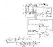
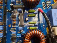
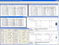
I thought I would post this project of mine. This is a tube ambiance processor. It is the same principle as the famous Hafler box of the 1970s but implemented at line level using tubes.

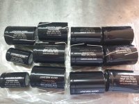
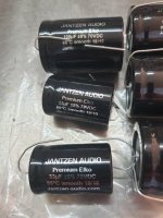
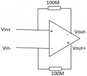
It was built from junk box parts. The only draw back is low gain - the unit is very lossy on it's output but you can probably fix that by changing V2 to a 12AX7 and also it's resistor values. I just made up the gain in the mono amp following this unit.

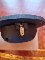
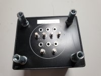
A relay was used as the null bypass switch to keep the program audio paths short and restricted to the rear panel.

I like the effect. I have four dipole surround speakers that serve double duty with the TV AV receiver. I just series/parallel them for 8ohms when on the tube amp. I use a DIY 6BQ5 PP amp that puts out 10 watts max.

Try it if you like. Also any design comments are appreciated. As for the purists, yes I know, you don't want tone controls or gimmicks like this in you system. But that device can be simply turned down or off if the effect is not to your liking in a particular track. Like any audio enhancement device less is more. The effect is subtle when adjusted properly. You should not be able to pin point the surround speakers sound wise. Otherwise the surround level is too high.

Attachments

  • Tubesurr4.jpg
    Tubesurr4.jpg
    226.2 KB · Views: 168

Side-mounted woofer question

After reading up on side mounted woofers, it seems the consensus is that they work fine if crossed over below 200 hz or even lower. My question is if it is preferable to have the side woofer mounted closer to the baffle, or if it doesn't matter.

I picked up 2 high quality 1" thick plywood cabinets from a thrift shop, for $40 each. The overall dimensions are 16" wide x 24.75" deep x 32" high. There is a 3" raised plinth on the bottom, so the inside dimensions are 14" x 22" x 27". The difference is accounted for by some round-over trim I will remove. These are rabbeted, and heavy duty. I will make a new baffle, and use them in an on-going project for a high efficiency speaker. I plan to brace them extensively.

Years ago I bought a bunch of TAD drivers, and have some gorgeous 1201h mid bass sitting on the shelf, NOS. I'd like to mount them high on a new front baffle, and find something to use on the side that can keep up with the TAD 100db/1w/1m. I have some DIYSG 15" Eminence "buyout" custom woofers, but their efficiency IIRC is about 88db. Dual side mounted woofers for force cancellation would be really fun, as long as price is reasonable. The TAD would be run from about 150-200hz up to 1000hz. Above that would be another box, yet to be determined. I have JBL horns I can mount quickly and give a listen.

These would be well out from the walls in a 23' x 22' x 9' room. Not ideal. Listening position about 10' from speakers.

Are there specific issue I have to avoid in this scenario? Thanks!

6 channel amp - run 240V feed from breaker box?

Have a question for those with expertise in this area...

I am planning an active 3 way system with 6 channels of purifi amplification. I know that the smps used for these modules can be configured to run on 240V as well as 120V. I am in the US and have 240V available at my breaker box. I am pondering running a 240V feed to a 240V outlet and running the amps with the smps' set at 240V. I would use powercon plugs and a 30A breaker in the breaker box. I thought this would make more sense than running multiple circuits to multiple outlets.

Any cons to the idea?

Advice needed: 0.47 uF film cap DC for tube output

Hi,

I need please an advice for a 0,47 uF film cap as DC blocker output for a DAC. Typically : E188CC or 6N23PE-EV outputs.

I thought about : a NOS Philips styrenes that are lead foilded if I remember, but too much dry sound in serie ?

Nos ERO KP ?
Nos ERO MKC ?
a soviet teflon or a soviet paper in oil ?
break the wallet and a modern Miflex copper ?
I also know Torsten Loesch appreciated the Solen leads for the purpose ?
Etc...
Your experience welcome, no money for a Tango transformer, Lundhall, etc !

Many thanks :wave:

Neg Speaker Binding Post QSC PL 6.0 PFC

I need to replace a broken speaker binding post from my QSC Powerlight 6.0 PFC amplifier. It is the black negative post that broke off. I attempted to weld it back together but that was unsuccessful.

The service manual describes the part and part number.

CO-000146-00 BINDING POST, SINGLE, 1 POS, FEMALE, 60A BLACK

I am asking here because QSC parts said this item is discontinued and out of stock.

I have been unable to find a suitable retrofit. So I'll need to get spares from a donor unit most likely.

BindingPost1.png

Speaker Placement Rectangle Room

Hi Everyone,

I'm moving into a place and need to decide which is the best wall for my speakers and listening position. All the advice online shows enclosed rooms, which doesn't help with real world open living floor plans.

Do I place on the short or long wall? I have some difficult doorways and kitchen etc.

I intend to have two bookshelf speakers (B&W 805) on stands and a 3 seater lounge in this room. I also want to install panels to first reflection points and possibly ceiling.

I've attached a layout and some photos from the realestate listing.

Really appreciated your input.

Attachments

  • Screen Shot 2021-06-13 at 9.21.21 pm.png
    Screen Shot 2021-06-13 at 9.21.21 pm.png
    294.7 KB · Views: 220

Is it possible to replace the OPT with different specs for 300B PSE?

I used to ask Patrick 2 years ago with questions but recently haven't heard from him. Hope, he is doing well.

In his reformed Jadis 300B PSE, he used Hammond 2k5 impedance. Can I use Edcor CXSE25-1.25K impedance so I can remove some of the parts on the output transformer? Even Hammond has 1.25k impedance OPT but he picked 2.5k.

Patrick's website: jadis-300b-reformed

Jadis-SE-300-B-OPT.png

Best AMT on the market ?

Hi all

Long time that I don't post/interact here on this forum.
Basically, after I found my dream duo, Beyma 12P80nd/TPL150, i lost interest in DIY, and just so in trying out new stuff.
Thats about 8,9 years by now.
Wondering: Since then, has there be launched any AMT mid-tweeter that tops the Beyma TPL-150 in terms of performance, in special low distortion, and naturalness/neutralness/transparency?

Otangelo

Amplifier LF Peaking in Ltspice

Hello .Just playing with this old amplifier schematic in LT Spice and gives a low frequency peaking.How dangerous is this in real life?It has to do with the different R-Cs and low corners that are close to each other but how to find the and eliminate it?

Attachments

  • 1.jpg
    1.jpg
    156.3 KB · Views: 170
  • 2.jpg
    2.jpg
    391.4 KB · Views: 158
  • s210.asc
    s210.asc
    8.5 KB · Views: 61

Too much MDF... help me build some boom

Long story short, I have a buttload of MDF, mostly 3/4" but also some 1" and some 1-1/4" Then last week I received a couple crates of high-end lumber that was packaged in 3/4 MDF, so I now have two huge 72" x 64" sheets to add to the pile.

I work for a performance theater and I've been craving more boom than my single Yorkville gives.

I have a very large shop

1 + 1 = 2. Let's make booms.

Wants:
Size - not really an issue. For once I have plenty of space for something with volume, so something like a tapped horn or bandpass isn't out of the question.
Freq - basement. The rest of my pre-amp equipment is all good for down to at least 10hz (not that I need that low), and there is just something about a good shake from 17hz when I have a thunder sound effect. The Yorkville does great in the upper 30s, So shall we say 18-40hz?
Budget - technically zero, but I have the MDF and materials to build it. Drivers will likely cost money, but I have a guy who might want to trade me some drivers for a snake I have. Having said that, if I have to buy drivers it seems like a huge jump to go to 18s, so maybe 15s would be wiser.
Amp - up for debate. I would love to splurge on a plate amp. Running XLR to it will be easy. Running speakon from the rack will be a pain. Truthfully I could probably just do a rack mount amp screwed to the box somewhere.
Appearance - ugly. It will be hidden under the seating risers, or possibly even under the stage.
DB - doesn't need to be insane. Most of what we do is live performance theater and musicals. We do occasionally have musical concerts, so having some louder potential will be nice, but no need to make it louder than the Yorkville.

So let's talk. Links? Ideas? Designs?

Soft Start Circuit Help

Hello Everyone,

I'm planning to put in a soft start circuit for the class A/B amp I am building now, which has 2 x 350va toroidal transformers and total 80,000uF of smoothing capacitance (20,000uF for each power rail).

I want to go on the safe side and the one by Ron Elliott seems to be a decent and simple enough one to build. (see figure 5 on Soft-Start Circuits)

Ron's notes suggest that the soft start time is 100ms, but I am thinking of increasing that to 500ms to 1sec, but I am not sure which component / value to change to enable a longer soft start time.

Can someone help me with some advice?

Many thanks and have a safe weekend.

Need help with a DAC build (Bloodac 4 x TD1541)

Hey All,
I recently acquired a Bloodac 4 x TDA1541 DAC board and 4 TDA chips. I've been trying to complete the project but I'm very new to DIY and need some assistance. I reached out to FMs that have previously built this board with no reply (maybe my mistake of reaching out through DMs directly).

I have also reached out to the seller of the board Raindrop Hui but haven't been able to get the design files yet.

From the board I can see that some of the regulators are missing heatsinks and a capacitor is missing. I have ordered the missing components already. I'm trying to get it to working condition before doing some tweaking (Lampizator has mentioned a few upgrades for the board).

One question I have with going ahead is related to the toroidal transformer that I should use for the board. The board itself has 2 x 11VAC and 4 x 18VAC inputs so I'm not sure what transformer to pick/buy. I contacted a local transformer maker and they asked me what amperage I want on the secondary section. I'm not new to electronics but I'm very new to DIY audio so I wanted to start a thread here to get some help.

I have attached images of the board and the link to lampizators post is: fourTDA_dac

EDIT: Link to board images Bloodac 4 x TDA1541 - Album on Imgur

Balanced BA-3 w/Salas Regs, Dual Mono and Goldpoint Volume pot, Fully Assembled

Hello, I built this a couple of years ago to go with a pair of balanced F4's I built.

I used top-quality parts throughout and the result is a really nice preamp. I've been using a pro mixer/audio interface as my preamp since moving to active crossover speakers and the BA-3 has been on the shelf in my climate-controlled shop. I'd love for someone to get some use out of it; easily the best active preamp I've ever listened to.

I'm in Southern NH USA and will happily meet anyone within 100 miles of Manchester. Otherwise, I can ship double-boxed anywhere at the buyer's expense.

It's pretty heavy with the dual toriods so shipping won't be cheap to Europe or Asia.

Asking $1,000+shipping.

HT ss stabilized

Hi

in attach the test on FFT by AP about the HT voltage just after the bridge, around 350 vdc with 330 uF as filter cap and bridge of 25A.
Then at the output of HT stabilized circuit I normally use.
The current is 20 mA ( is a line tube stage).
The results is interesting.

The attenuation on region from 30 to 2kHz is very fine.
At 100 hz the difference of the two peaks is 100 dB; same for the other multiplies (less or more)
Personally in each stage, line or phono, I use this one because it helps a lot also for s7n.
In additon the screenshot from scope on wave at input of board, in out and the residual

Walter

Attachments

  • HT_input_out_stabilizz.pdf
    HT_input_out_stabilizz.pdf
    32.9 KB · Views: 148
  • HT_input_bridge+330uF_325vdc.jpg
    HT_input_bridge+330uF_325vdc.jpg
    88.9 KB · Views: 332
  • HT_out_stab.jpg
    HT_out_stab.jpg
    43.5 KB · Views: 331
  • Scope_residual_input_short.jpg
    Scope_residual_input_short.jpg
    43.1 KB · Views: 323

Hifonics class d,problem with the high-side gate signal

i have a problem with my hifonics brutus bxi 1100d.after output fet failure,the gate signal of one high side bank is not clean and the fets get hot(the two with the heatsink).the other high side and the other both low side gates are ok.i replaced the fets,the gate resistor,the hip4080,the lm393 left of the hip4080,the lm833 and the 6,2v zener diode"ZD1".this diode gets relatively hot,about 100 degrees.on another amp its only 50 degrees

the amp works,but sounds distorted.see the photos.pic 175705 good gate
pic 175712 bad gate
what could be the problem?

Attachments

  • 20210630_175335.jpg
    20210630_175335.jpg
    1 MB · Views: 129
  • 20210630_175434.jpg
    20210630_175434.jpg
    1,001.9 KB · Views: 121
  • 20210630_175526.jpg
    20210630_175526.jpg
    1 MB · Views: 121
  • 20210630_175705.jpg
    20210630_175705.jpg
    655.2 KB · Views: 114
  • 20210630_175712.jpg
    20210630_175712.jpg
    676.7 KB · Views: 110

problem with the high-side gate signal

i have a problem with my hifonics brutus bxi 1100d.after output fet failure,the gate signal of one high side bank is not clean and the fets get hot(the two with the heatsink).the other high side and the other both low side gates are ok.i replaced the fets,the gate resistor,the hip4080,the lm393 left of the hip4080,the lm833 and the 6,2v zener diode"ZD1".this diode gets relatively hot,about 100 degrees.on another amp its only 50 degrees

the amp works,but sounds distorted.see the photos.pic 175705 good gate
pic 175712 bad gate
what could be the problem?

Attachments

  • 20210630_175335.jpg
    20210630_175335.jpg
    1 MB · Views: 140
  • 20210630_175434.jpg
    20210630_175434.jpg
    1,001.9 KB · Views: 167
  • 20210630_175526.jpg
    20210630_175526.jpg
    1 MB · Views: 134
  • 20210630_175705.jpg
    20210630_175705.jpg
    655.2 KB · Views: 127
  • 20210630_175712.jpg
    20210630_175712.jpg
    676.7 KB · Views: 122

Negative feedback and distortion

In this Wikipedia article:

Tube sound - Wikipedia, the free encyclopedia

it is said that negative feedback causes inter-modulation distortions but the references are unreachable.
Can someone give me some serious references that explain this phenomenon and maybe model it, etc. ?
I am curious if this type of distortion is the reason some audiophiles reject the circuits with negative feedback. Maybe they are onto something ? 😕
Any comments and ideas are appreciated.

Distortion vs Global-Feedback (simulated)

I have made the amplifier with separate voltage amp stage and power buffer. I don`t have measurement tools so I simulated distortion vs global NFB.
Input voltage amplifier has local 6dB feedback loop and it is constant. Only global feedback loop around buffer is changed for different data:

On the graph X axis is 2nd, 3rd, 5th and 7th harmonic. Fundamental is 20KHz.
On the graph Y axis is distortion %.
Separate colors are for 0dB, 7dB, 12dB, 14dB and 22dB of GNFB.

Attachment is block schematic and chart data, it might be interesting to someone 🙂

Input stage is complementary jfet/bjt and the power buffer is a all bjt triple EF.

P.S. Interesting thing is there is no 5th and 7th harmonic rise with raising feedback factor as some are advocating...

Attachments

  • block-schematic.jpg
    block-schematic.jpg
    34.3 KB · Views: 431
  • hs-vs-dist-01.jpg
    hs-vs-dist-01.jpg
    180.7 KB · Views: 426

THD measurements

Hi,

I’ve done some THD measurements on my breadboard 6SN7 - 6SN7 - EL34PP project. THD measures 0,39% with 36 Watt output. Now my signal generator has 0,10% THD for 0,32 Volt PP input. My USB audio input also has approximately 0,10% THD.

What THD figure is “real” for the amplifier part only? Should I calculate 0,39 - 0,10 - 0,10 = 0,19%?

Regards, Gerrit

How to measure THD

I am one of the ones who learned electronics backward. First I learned how to fix them then I learned why what I did fixed them, so there are holes in my education. To the point. Recently I completed a very nice sounding 20WPC all triode power amp using 6AS7s for the outputs.🙂 I then bought a used HD Meter and a new Audio Sig gen speced at .018 % HD. The meter confirms the Generators output. So I decided to measure the stage by stage distortion in the amp (it has no feedback). The first voltage amp showed a distortion of 0.4%.🙁 It is one section of a 12AX7, 180 plate supply, 82K Rp, 470 ohm Rk, 470K Rg, with a .04 input and output coupling caps and a 2 ufd Ck. Measurement shows a Vg of ~40 ( 50mv in 2V out). with .4 % distortion.

I then breadboarded that stage. Yep .4 % is as low as I can get it at any reasonable amplification factor.

Now the questions. Is that an unusual amount for one stage? Are HD artifacts additive as you add stages. I assume they are? My Dyna PAS2 specifies HD as being "below that measurable by (back then) modern equipment." To me 0.4% means if I had 4 stages like the 1 stage in my amp the distortion for the amp would be ~1.6 %. What am I doing or thinking wrong? Is .4% a good number for one amplifier stage? 1.6% (.4 x4) is certainly not a good figure for a preamp.😕 Its all very possible that I should quit nit picking and enjoy its openness and what I describe as clarity.🙂

Thanks
Ned

NAD 2150 with swapped Transistors

Picked up a NAD 2150 recently. Sounded good, seller said it was all original. Brought it home and opened it up, and looks like 2 of the Sanken Transistors were swapped out with Toshiba (and a messy soldering job).

This goes a bit beyond my knowledge... anyone have experience? I suppose I'm just looking for thoughts in general. How does this effect the sound?

Thanks.

Attachments

  • nad2150 - Copy.jpg
    nad2150 - Copy.jpg
    1.1 MB · Views: 494

Assistance with SigmaStudio

Howdy folks, i've just built some 2 way active stereo monitors using a Sure/Wondom JAB5.
I'm using 1 channel per driver, so 4 channels.

Am trying to figure out how to use the software, i've watched the Wondom instructional video as well as a few others online. Most appear to indicate that i should be able to listen to sound whilst having the ICP1 programming module - so i can tune on the fly.
however so far i can't get sound out of the amp when the ICP1 module is connected. (i do get sound when it's disconnected)
I've got the hardware configured as per Wondom's instructions, the USB is green indicating it's connected.

I've got the inputs set up and DAC's set up for the output in the schematic.

Any comments/suggestions on how i can get sound from the amp while i'm tuning the crossovers? Would prefer not to have to write, disconnect, listen, reconnect, adjust, disconnect, listen etc etc etc.

Thanks!

FS: Audiophonics DAC I-Sabre ES9038Q2M Raspberry Pi DAC HAT (Micro USB Version)

Selling my much loved Audiophonics DAC HAT. I used this with a Raspberry Pi 3, and PiCorePlayer as the player. Never missed a beat, handling high res audio (PCM and DSD).

More info here: AUDIOPHONICS DAC I-Sabre ES9038Q2M Raspberry Pi / I2S & SPDIF / PCM DSD USB-C Power Supply - Audiophonics
(Note that's the USB-C model - the only difference is the power supply interface - otherwise it's identical)

After $80 USD.
The item is in Australia, so shipping will be on top of that price.

Attachments

  • IMG_20210628_200151.jpg
    IMG_20210628_200151.jpg
    297.1 KB · Views: 311

Why do some valve datasheets show triode strapped screen current?

I’m approaching this question from a historical perspective.

I know a lot of these valves are not intended for audio use. So what is the intended purpose of having curves like this in datasheets?

It’s shows the the screen current when triode strapped as a function of screen voltage. This must mean that designs would take current from the screen rather than the anode? What’s the consequences of that? Much lower currents!

Attachments

  • B98C3117-A5F1-473A-8C9A-5FE3D66A05C2.jpeg
    B98C3117-A5F1-473A-8C9A-5FE3D66A05C2.jpeg
    578.6 KB · Views: 247

Crossovers for Emerald Physic EP4.4

Has anyone made crossovers for the 4 series EP’s

I have a pair and no crossover. Trying to make a passive crossovers w as little fuss as possible. All I know is what I’ve found online. Third order w points at 250hz and 1k hz

Someone sent me a photo but I can’t read the capacitor values. It’s
Pretty simple though. 3 metal oxide resistors. 4 wire wounds. 5 solen caps.

Amp and parasitic draw

Hi
It wasn't easy but I traced my parasitic draw to 1 of my 2 aftermarket amps. The culprit is showing.. .075 A to.. .098 A draw at the battery after the vehicle pcm/ecu goes to sleep.

If I remove the remote wire from the culprit amp, the draw remains. If I remove the 4awg power wire from the culprit amp, the drain drops to,. 016.

My dist block takes the 4 awg wire from battery and outputs one 4awg and one 8 awg. I don't have a drain with the 8 awg amp and dist block..until I connect the 4awg amp.

Could I please get advice how to proceed? I have no noticeable issues, works great and fuses are fine, and a brand new batt.

Kef B200 SP1069 and Isobarik configuration

Please can you help with advice. I have an old pair of Kef Concord 3s, and I would like to know the specs of the B200 SP1069 drivers. These were Kef's budget speakers of the 70's and are not worth a great deal, so I thought they might make an interesting project if I reconfigured the SP1069's (there are 2 in parallel in each speaker) to sit in Isobarik configuration.

I've never thought the Concords to be particularly good and never understood the logic of having two drive units pressurising the same enclosed space. They may be operating at different frequencies (apart from the crossover zones), but they would still apply unwanted back pressures on each other.

I understand that the two SP1069's currently combine to form a 'notional' 8 Ohms impedance, and that this would not change when placed in Isobarik parallel configuration. I also understand from reading about Isobariks, that none of the other speaker parameters will change too much .

I appreciate that the crossover will need adjustment.

Many thanks,


Any advice and/or data on the Sp1069 would be greatly appreciated.

Soundstream D200

Im servicing an original 'heater' version D200 amp here, with TIP35 BJTs in the PS and TIP141/TIP146 output darlingtons.

The 'outer' PS had several failed components including almost ALL 1n914 diodes, a 15v cap, and an MPSA92. Replaced all. TIP35 are OK.

The 'inner' PS had two failed 1n914 diodes and a failed MPSA92. Replaced all. TIP35 are OK.

On the amp side,
The 'outer' channel also has a failed TIP146 which I've removed for now.


The amps and PS are connected as such.
'Outer' PS is connected to the 'inner' amp (Marked in YELLOW in the below photo)
'Inner' PS is connected to the 'outer' amp.


Fully powered and only minus the failed TIP146, the amp idles at about 2.3A. The problem I'm seeing though, is the 'outer' ps is only producing +-36vDC rail, while the 'inner' ps is producing +-46vDC. Thats quite a significant difference from channel to channel imo.

Any thoughts as to why such a difference with this amp?

Photo next post.

Simple B+ delay circuit for tube power amp?

Can someone suggest a simple B+ delay circuit for tube power amp with full-wave diode-rectified B+ around 450VDC?

I found some circuits for solid-state amps, none for tube amps -- except many references to why tube rectifiers are superior, etc.

The idea would be... Turn power switch on, heater supply turns on immediately, ten seconds later the B+ gets switched on.

Thanks.

Lower VAS current and Darlington Triple

I was playing around in ngspice and was wondering why a particular design decision is typically made.


When output stages are designed for output power greater than 200 W, typically for Darlington stages, even triple stages, higher VAS currents are used on the order of 10 mA. This requires the use of transistors like 3503/1381 pair for the VAS to handle the power dissipation of a rail voltage greater than 50 V and 10 mA (or about 500 mW to 1000 mW static dissipation). However, why is 10 mA needed for a triple Darlington configuration? In the designs like below, 2 mA seems to be sufficient for a triple Darlington, which for 70 V and 2 mA would be 140 mW of static dissipation, well within the range of a TO-92 device such as 2N5551/2N5401.


Is this a matter of just wanting the extra current to make sure there is no VAS distortion? Or is there some other reason for it? It seems to work (at least in simulation) with less VAS current and a triple as the higher current gain in the triple makes up for the lower VAS current.


I am interested in this question because I am curious about how to pare a design down to the barebones to get good performance but not require anything too fancy.

Attachments

Audio Pipe APCLE-15001D

Working on an audio pipe amp. All output were burned up and drivers shorted. Replaced all the drivers. Checking drive signals before installing outputs. I have what looks like ringing on the 5 volts to the high side drive. The ringing follows all the the way out to the high side drive on the outputs. Is this normal? I put one output on each side to test and it shorted them as soon as I powered the amp. I have good signal on the driver board itself.

Attachments

  • 20210701_115443.jpg
    20210701_115443.jpg
    922.2 KB · Views: 76
  • 20210701_115540.jpg
    20210701_115540.jpg
    703.2 KB · Views: 72

Ciare PT383, Seas U18RNX/P crossover opinions needed

Hi everyone,
I am planning to build a 2-way floor standing speaker using the following drivers
Tweeter: Ciare PT383
Mid/bass: Seas U18RNX/P
Box size 34L, bass reflex, port length 140mm diameter 58mm

I tried simulating a crossover in LspCAD 5.25 and have found a possible solution, see picture. But I am not sure if it is ok.
It was really difficult finding a good linear fit, the only one that looked good was a 2nd order 1300Hz LP and a 3rd order 2600Hz HP network.
I have only adjusted the values of the components a little so that they fit standard components which can be purchased.

Thank you in advance for any opinions/suggestions
Paul H

You will also find the frd and zma SPL and imedance data files for these drivers attached in the zip file.

Attachments

  • 110104_W18_LSPCAD_project.jpg
    110104_W18_LSPCAD_project.jpg
    302.9 KB · Views: 767
  • SPL data.zip
    SPL data.zip
    9.6 KB · Views: 153

Ore Audio SA3000.1 No audio

Working on an Ore Audio SA3000.1. Power supply is running. I have rail to rail oscillation but no audio. I have signal to the driver board. The LM311 on the drive board is running hot to the touch. Anyone familiar with this driver board?

Attachments

  • 20210630_124752.jpg
    20210630_124752.jpg
    635.4 KB · Views: 94
  • 20210630_124809.jpg
    20210630_124809.jpg
    991.8 KB · Views: 85
  • 20210630_124819.jpg
    20210630_124819.jpg
    900.8 KB · Views: 76
  • 20210630_125025.jpg
    20210630_125025.jpg
    818.4 KB · Views: 94

Problem with WaveGene.

Hi All.

I use WaveGene many years, it is a very useful tool. Unfortunately, its development finished 4 years ago the Author does not reply.

I had a problem in the past, them it looks like the problem was disappeared, but now it coming back again.
With other source, there is no this phenomena with the same equipment: USB DAC + USB ADC, (doesn't matter which model, tried at least 2 different ADC, UAC1 and UAC2, and 34 different DACs, all UAC2).
UAC2 ASIO driver for DAC.

Visually, it looks like it skip samples sometimes - spectrogram is jumping and is much higher (see the picture attached).

WaveGene 150E - used it at my previous desktop PC with Win7/32.
Everything was fine at the beginning, but after few year this problem occurs - only at 44/48 sample rate! 88-384 were fine.
After don't remember how many time, the same began at 88/96.

I changed PC, with Win10/64 everything was fine at the beginning, then this happened again.

Few days ago, I worked with a DAC with 192K limit, and this problem happened with samplerates, from 44/1 to 176, after few hours - all samplerates, from 44/1 to 192 were bad!
With another DAC, with 384K limit - all samplerates, from 44/1 to 192 were bad, but 384 works normally.

Yesterday evening, I downloaded an old version - WG140, and it works fine at all samplerates! But, I don't know, how long this fine work will be 🙁
Also I often need WG150, because WG140 is limited to 2 channels only.

I took the old netbook, where WG150 was installed in the past, but was not used many times.
All >88K were fine, 44/48 - problem.
It seems to me, that the problem depends of how long or how many time I use each sample rate.

What is it, WaveGene have a time-bomb ?
Has anyone faced something similar?

Attachments

  • WG_Bad.png
    WG_Bad.png
    18.4 KB · Views: 141

PIoneer DV-S9 tray eject after disc reading

not sure if any of you have seen this problem on your CD or DVD player...

I have a Pioneer DV-S9, a solid tank DVD player, recently it started to behave strangely (You may refer to the video link attached).
I have owned other players, in case of laser failure they will show "error" or "no disc" on the display and there will be no red dot, or in case of spindle motor failure the disc will not rotate...
But this time the player is too weird for me, the reading sequence started normally, the laser moved and the red dot is clear, but seems like the player cannot recognize the disc and then automatically eject the tray.
I've checked the PSU, outputs are all OK, checked the caps on the boards and they seem still intact, checked connectors and flat cables and they are all good...

Pioneer DV-S9 tray ejecting after disc reading - YouTube

Any clue? What do you suggest me to further check? thanks.

Quad ESL57 EHT resistors

I'm rebuilding the EHT power supplies in my ESL57s. Do the 330k and 2.2M resistors need to be high voltage parts or will standard resistors do? How about the resistors in the audio transformer box?

Also, one of the dust covers has a tiny, tiny pin prick hole in it - I've read that the solution is to put a small piece of tape over these defects, but also not to use sellotape - but then, what tape should I use?

Thanks

Nat

Marantz PM-80 questions

Hello everyone, new member here, not an expert in this kind of stuff so sorry if I'll be asking stupid questions.

I got the infamous Marantz PM-80 amplifier recently. It works great, I like the sound, its in good condition and basically I'd like to keep it that way so here are my questions. Before getting it I used active speakers with Project Debut Carbon turntable, so I have a Project phono preamp.

Question is should I use this preamp with Marantz or not, because I red that most common problem with this Marantz is STK, and I also red somewhere that the STK module is used for preamp part of Marantz, so if I use other preamp will there be less chance of STK failure?

I live in a small apartment, I don't listen music too loud, I hear no big difference in sound.

One more question, about class A, should I turn the amp off before switching to it? I red somewhere that I should, but saw some videos where people don't do it.

EPOS ES -12 speakers SoCal

Hi,

I have a pair of Epos ES-12 speakers looking for a new home. Acoustically fine, one has some corner damage top front left corner, so they not perfect. Grilles are great. i can post pics if there is interest.

I am in San Diego, shipping would be killer, so thinking local/SoCal sale for now and looking for $300 for the pair

Let me know if there is any interest.

Various questions about DIY line preamp

Hi all,

as of now my setup is an Audio Research SP9 preamp and a twin KT88 power amp, there is a turntable which sees no use (because of space constants), plan is to build the F4 to power the JBL L220 and put the tubes on the side, the F4 should do nice with the hi gain of the SP9 but I was wondering how difficult would be to build a preamp.

For the F4 am gonna ask a dear and skilled friend to build as that's too much for a first timer with limited experience and instruments like me but was wondering about an unbalanced line preamp to match the F4 (ideally I would delegate the AR SP9 and KT88 to a secondary stereo to use my older JBL4311b), how difficult would it be, how expensive and if it would have the about 20db gain to drive the F4.

Any input welcome


Grazie


Giovanni

Sonance Sonamp 1230 Sudden Buzzing Sound

Hello,

Issue:
All of a sudden through my speakers I am getting a loud buzzing sound. This is on all the channels.

I read that possibly it can be a lifted ground wire. To verify I tried a power cord with no ground, seeing if bypassing may work. Still buzzing.

I looked at the power supply board, and I am not seeing any blown capacitors. What else can I try to diagnose. Since on all channels, should be a power supply issue?

Thank you for any help.
JR

FS:HIFI2000 GALAXY CASE NEW

FS BRAND NEW UNUSED AND HARD TO GET(BREXIT/TAXES) GALAXY CASE (40 mm high x 230w x230 deep.10mm front. PERFECT FOR KORG PREAMP KIT/DAC OR OTHER PREAMP PROJECT. £45 DELIVERED.UK SALE ONLY.

Attachments

  • BE326C7C-9484-4C48-BBB1-C8B220FCBB15.jpg
    BE326C7C-9484-4C48-BBB1-C8B220FCBB15.jpg
    674.4 KB · Views: 368
  • 3096E4F7-1632-44A0-BABF-101AB2CA765B.jpg
    3096E4F7-1632-44A0-BABF-101AB2CA765B.jpg
    586.7 KB · Views: 359
  • A9301E76-7C2B-4D87-88E3-390D42FA51BB.jpg
    A9301E76-7C2B-4D87-88E3-390D42FA51BB.jpg
    658.5 KB · Views: 337

How to calculate Zobel Network/Boucherot Cell for Solid State Power Amplifiers

Most commercial and diy power amplifiers uses on it's outputs values inside of a small range:
The resistor values goes usually between 2R7 and 15R (mostly 10R or 4R7 according the most amplifier books the value of DC resistance of most speakers for home audio) and the capacitor values goes between 47nF and 220nF (mostly 100nF)

But sometimes there are to observe very strong deviations.

Linn's early version LK2 (LK-280) e. g. uses only a 100nF capacitor without resistor at its output. Later versions additional use a network consist of a 330nF capacitor and a resistor of only 0R47 (470mR).

Maybe this is necessary by the use of a sziklai darlington (CFP Pair) in the output buffer, but I don't know this exactly.

Are there a calculation basis, where this is comprehensibly ?

Thank you for comments and advices to appropriate websites.

Under the follow threads there are no advices therefore, because the aim is mostly an appropriate zobel network for certainly loudspeaker drivers:
Boucherot cell (Zobel network) values
How to calculate Zobel/Boucherot Circuit
No Boucherot cell?
Amp Stability techniques: Zobel et al.
DIY option for spectral amps?
Confuse... When to use a Zobel network ?
Zobel network
Zobel network - resistor wattage
zobel network in MOSFET power amplifiers
Zobel calculation, help needed!

https://elektroniktutor.de/analogtechnik/zobel.html
http://www.jobst-audio.de/tools-frequenzweiche/zobel-glied

FS Seas T35C002 dome tweeter

Selling the new Seas T35C002 dome tweeter, only 1 tweeter available.
Item is new, never used, soldered or connected to anything, in the original box.

The T35C002 is a classic dome midrange tweeter with high sensitivity and a smooth, extended frequency response. A coated fabric dome with integral surround manufactured by Dr. K. Müller in Germany ensures excellent performance and consistency. This supplier was among the first in the world to offer fabric dome diaphragms, and did produce the diaphragm for the famous 1.5” Dome Tweeter H087, developed by Seas in 1968. A small, high efficiency Neodymium ring magnet in a carefully designed system contributes to high sensitivity and low distortion. The top plate and T-yoke are CNC machined for excellent precision. A well damped vented pole and a rigid rear chamber ensure a low resonance frequency and smooth response. A generously underhung 35mm voice coil wound from copper-clad aluminum wire further enhances the sensitivity. Flexible lead-out wires and venting holes in the aluminum coil former help reduce noise to a minimum. A 7mm thick precision die-cast aluminum front plate with moderate horn loading ensures linear frequency response and represents an extremely stable platform for the magnet system and the moving parts.

Specification

Nominal Impedance 6 Ohms Recommended Frequency Range 1500 - 25000 Hz
Short Term Power Handling 250W Long Term Power Handling 100W
Characteristic Sensitivity (2.83V, 1m) 95.0 dB
Voice Coil Diameter 35mm Voice Coil Height 2.0mm Air Gap Height 3.0mm Linear Coil Travel (p-p) 1.0mm
Voice Coil Resistance 4.6 Ohms Voice Coil Inductance 0.06mH
Force Factor 4.3 N/A
Free Air Resonance 620Hz
Moving Mass 0.47g Effective Piston Area 11.9cm2
Magnetic Gap Flux Density 1.6T
Magnet Weight 35g
Total Weight 0.37kg

160 USD + 20 for shipping.
Paypal, buyer pays fees

Attachments

  • 20201105_151657.jpg
    20201105_151657.jpg
    162 KB · Views: 187
  • 20201105_151651.jpg
    20201105_151651.jpg
    99 KB · Views: 183
  • 20201105_151705.jpg
    20201105_151705.jpg
    51.1 KB · Views: 188
  • 20201105_151712.jpg
    20201105_151712.jpg
    57.3 KB · Views: 175
  • 20201105_151628.jpg
    20201105_151628.jpg
    118 KB · Views: 176
  • 20201105_151633.jpg
    20201105_151633.jpg
    77.8 KB · Views: 56

FS Jantzen Audio Premium Elko 100 & 33 uF

Hello all,

Selling the Jantzen Audio Premium Elko caps:
100 uF - 10 pcs - 10 USD each
33 uF - 2 pcs - 5 USD each

100 USD for the entire bulk.

Prices are -30% vs retail.
Caps are brand new and never used, excellent for mid or bass x-overs in tight compartments.

Shipping from Moscow, Russia. 20 USD registered airmail to anywhere, please contact me for the exact cost to your destination.
Paypal, buyer pays fees.

Thanks!

Attachments

  • 1.jpg
    1.jpg
    176.7 KB · Views: 369
  • 2.jpg
    2.jpg
    100.9 KB · Views: 363
  • 3.jpg
    3.jpg
    100.7 KB · Views: 376

Monolith magnetics 2*6.3V 2.5A per rail power trafo

Selling beautiful transformer from Monolith Magnetics: dual c-core, 230V primary, 2*6.3V secondaries 2.5A each, fully encapsulated in case-0.

External dimension WDH in mm: 87*71*101.5.

Great for use in high-end digital circuitry, mine was powering Ian MCFifo board.

Was purchased for 130 EUR, selling for 90 EUR.

Shipping via registered airmail with tracking, 10 EUR.
Paypal only, buyer pays the fee.

Thanks!
Daniil

Attachments

  • Monolith 1.jpg
    Monolith 1.jpg
    743.9 KB · Views: 689
  • Monolith 2.jpg
    Monolith 2.jpg
    889 KB · Views: 684

Class AB "endangered"?

Hi,

Last week I did a little research for currently available power transistors. I used Silicon Expert to look for available power transistors in TO-247, TO-3P and TO-264. I looked for complimentary BJTs, darlingtons, DMOS and to make it complete Lateral MOSFETs.

I started with (lateral) MOSFETs and noticed first, that Exicon is not a listed manufacturer in Silicon Expert. Then I continued with DMOS and I noticed, that there are only very few PMOS available anymore. Even with BJTs (incl. Darlingtons), there are comparatively few types still available, although more then complimentary MOSFETs and in contrast to MOSFETs BJTs are also specified as complimentaries.

Is class AB/B dying out? 😕

Rotel RB990BX Grounding Issue

Hi, I have on the bench a Rotel rb-990bx power amplifier.
This amp have a serious grounding issues.
The input RCA jacks are disconnected from chassis ground and from each other.
I'm wondering if I can simply connect the sleeve of the input jack to ground? or by ding so I'll bypass the relay (RY801) circuit?
Here's a link to the service manual:

Attachments

Rescap Electrolytic pin-out/connection

Hi everyone!

I'm searching for the datasheet of a seemingly rather "exotic" (and old?) electrolytic capacitor marked with "Rescap 22000µF +/-20% 63V 40/105/56 Plus=1 XD". Here's a picture:

attachment.php


I do see that Pin1 is "+", but have ALL other pins to be connected to "-"? Or are there n/c pins as well? I'd be greatful for explaining information, especially about the connection pin out or best case a datasheet.

Thanks a lot folks!
Winfried

Attachments

  • Rescap Elko.png
    Rescap Elko.png
    533.6 KB · Views: 172

300b socket replacement

Hello,
I recently replaced a damaged ceramic socket for a 300b. The original sockets would only allow the tube to fit if oriented correctly. Two large pin sockets and two small, no way to install wrong. The replacement sockets will allow for incorrect installation of the tube if I’m not careful. So what did I get some crappy sockets or what? Just curious what others have to say
Thanks

Group Buy: Linear Systems LSK389 / LSK170 JFETs (i.e. Toshiba 2sk389/2sk170 subs)

well, well, well... I just got off the phone with my local distributor for Linear Systems parts and would like to see if there is any interest in these parts.

The LSK389 is a drop-in replacement for those pesky Toshiba parts, and reported by some to have better specs even than the original. Here's a datasheet:

http://www.linearsystems.com/datasheets/LSK389.pdf

available in the usual Idss flavors, but with different names.

Also, for your viewing pleasure is the now out of production single version of the above. Here's a datasheet:

http://www.linearsystems.com/datasheets/LSK170.pdf

The distributor says they might be willing to mix and match Idss grades for us DIYers, and the order target is 100 pieces of the LSK389 and 100 pieces of the LSK170. So, if you're interested please state your Idss preference.

Now for prices (assuming quantity 100):

LSK389 (TO-71 metal can):
"A" $6.08
"B" $5.87
"C" $5.59

LSK170 (TO-92)
"A" $1.13
"B" $0.95
"C" $0.80

There needs to be another 8.25% sales tax added to the above part cost and shipping is free as they're located in my backyard (almost literally).

Rules for the group buy will be very similar to what I did for the ROE MKP1837 group buy(s) and will be posted later on. I may instantiate a minimum order if I so fancy one as these group buys are lots of work. This will be easier than 6,000 little blue boxes, but still....

Shipping to you will probably be $2 in the US and $4 internationally, depending on quantity. I will only accept PayPal with a 3% charge for US and 4% charge for International. Upfront, you'll be responsible for the number of parts and the PayPal fees and I will bill you later for actual shipping and any other charges that might have cropped up due to mis-estimation (that's not a word, is it...).

Next price break is at 1000, which may be feasible if the heavy rollers step in 🙂 🙂

So, have at it!

Problem with DAC Audiomeca Ambrosia

Good afternoon.
There is a DAC Audiomeca Ambrosia.
The problem is as follows: when connecting the RCD (Rega Jupiter) via any of the 2 inputs of the Coaxial S/PDIF, and selecting the corresponding input by the input selector, the LOCK indicator, notifying, as far as I understand, about the normal connection, does not light up. At the same time, a continuous crackling is heard. Both devices are turned on. There is no way to check the operability using other types of inputs (BNC).

If there are owners of this DAC, tell me which cable (coaxial), how many ohms you use. I met information, that its coaxial input is designed for 100 ohms. Is correct?

I would be grateful for any help.

Odds / ends / deals.

$120/pair. 2010 era pair of lighter cone Betsy. These are slightly / lightly used, but if you’re matching an older era Betsy, this is the last pair I’ll be offering.
$60/single. 2015 BetsyK.
$400 almost new pair of Caintuck OB.

$20/each 2kV 10uF US mad vintage cap. 2 avail.
$10/each 2kV 4uF GE. 2 available
$100/pair Altec 1600V tube transformers.

$220/pair. Fostex D232. Almost NIB. 1 pair available.
$250/single 1 Altec 802 converted to FC by a gent in Italy. Never tested.
$40/pair Emilar 175, bad diaphragms.

I’ll post some pictures, more to come.

Vacuum Tube SPICE Models In Fusion360 Assistance

Hello,

I have been working to create SPICE testable tube amplifier schematics but am having a HELL of a time getting it going!
If I'm not mistaken, I have everything connected properly and built to decent enough standards. I built the 'symbol' as I was unable to find any as well as the 'footprint' for the same reason. I will attach a zip of photos of the issues I'm experiencing and what I've done as well as the datasheet I am currently using. Everything is properly assigned to models as far as I can tell: grounds, custom tube, resistors, and capacitors.
I'm not so much concerned about what the outcome of the SPICE test will be with the values implemented, more so just the capability to test! Any advice in what I may be doing wrong is greatly appreciated!

Thanks in advance,
Philip

Attachments

Yamaha CDX-1060 no display

I have an offer to buy a Yamaha CDX-1060 with a black display. I currently don't have access to the machine and don't know much about it other than that the display is completely black.

The seller explained that the remote isn't the original and could have set the display in an off mode and since the remote lacks the 'display' button, it might be a persistent mode that survives even when unpowered.

Is this true? If not, does anyone know if the display is a VFD that could've cracked and is for that reason unfixable? If it's another type of display, chances are that the fault may be fixable, perhaps a cracked PCB or a faulty display driver chip.

How do you prioritize project ideas?

When I find a new hobby or activity that interests me, I tend to dive in deep. My interest in tube electronics is relatively new, just a couple of years, but I've done some successful projects (and some failed ones!) And I've already got a long list of projects that I want to do.

Some are simple and straightforward, some are things that will stretch and grow both my patience and abilities.

Some examples - there are a bunch more, too. Some of these have already had preliminary design work or component purchases.
  • Build a Marshall 18W from scratch
  • Convert a Bogen CHB35A to something close to an AB763 Fender
  • Scratch design of a 6DY7-based stereo
  • Pair of 80W monoblocks based on the 6883 or 6159
  • Rebuild an HP rackmount VTVM
  • Add reverb to my Bassman

All told, I've got projects that could eat up the next several years. And in the meantime, I would surely come up with even more.

Does anyone else suffer from this "eyes bigger than your tummy" problem? How do you deal with it?

Op Amp voltage follower settling time

Good day, all
I have designed a 2 stage differential input and differential output op-amp with gain close to 45dB and phase margin of 60 degrees. I am trying to connect it as voltage follower based on Op Amp Voltage Follower Uses to check its response for a step input. I am connecting a large resistor between the (+)input and (-)output and vice versa. With VDD = 0.9V and VSS = -0.9V, and differential input 200mV, I am expecting the same differential output voltage.

However, I get an amplified output voltage (Almost -0.8V to +0.8V). I checked that the op-amp is not getting saturated. What am I missing? I want to check what time the output takes to settle.

Any ideas? Thanks a lot!

Attachments

  • op amp voltage follower circuit.jpg
    op amp voltage follower circuit.jpg
    18.5 KB · Views: 202

Sony PUA 237

Sony PUA-237, selling as parts due to missing third counterweight and repair required to anti-skate cam (shown in pictures). Really a great sounding arm. Way better than cheap Jelco or Rega. Maybe you can repair or use w/o anti-skate.

Asking $100 OBO.

Attachments

  • s-l1600-Resize2.jpg
    s-l1600-Resize2.jpg
    60.8 KB · Views: 120
  • s-l1600-Resize3.jpg
    s-l1600-Resize3.jpg
    70.2 KB · Views: 118
  • s-l1600-Resize1.jpg
    s-l1600-Resize1.jpg
    68.9 KB · Views: 117
Projects by fanatics, for fanatics
Get answers and advice for everyone wanting to learn the art of audio.
Join the Community
507,700
Members
7,884,880
Messages

Filter

Forum Statistics

Threads
406,066
Messages
7,884,880
Members
507,700
Latest member
Tomasz 026