Simple Vented Enclosure Design for Tang Band W5-2143

Hi All,

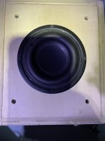
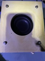
Hoping for some feedback from the community for my proposed design for the TB W5-2143 driver.

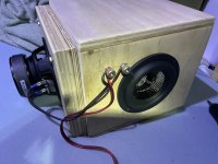
This will be my first ever diy speaker project, so my knowledge is pretty limited. Any help or advice is appreciated. I've seen a few other threads on more complex designs such as XKi design posted here, but trying to do a very simple full-range slotted-port bookshelf / stand-mount enclosure to match my pretty basic carpentry skills.

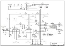
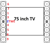
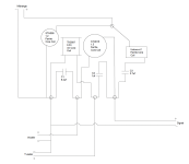
Here's the deisgn I have at this point:
Screen Shot 2022-03-16 at 9.41.43 AM.png


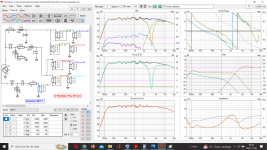
I've modeled this based on the output from the online speaker calculator here as I don't have access to other speaker-design software (I'm on a Mac - any suggestions for something else I should be using or even a simple excel file appreciated if there are flaws with that site)

That site gives the ideal ported volume at 14.02 L based on the driver parameters. I've calculated my net box volume above at 14.1 L (took an area of the cross section less slot volume, lining, and driver and mutliplied it by the net enclosure width less lining - I realize this does not 100% accurately capture the volume of the driver, so actual net box volume will likely be slightly higher, but hoping that's close enough).

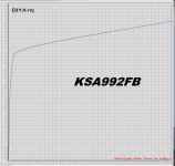
Here the outputs from the site:
Screen Shot 2022-03-16 at 9.50.13 AM.png


Screen Shot 2022-03-16 at 9.52.19 AM.png


Does this look good as a starting point? Any and all feedback appreciated. Thanks!

Antek AS-IT250 250Vx2, 6.3Vx2

I have 2 Antek AS-IT250 toroidal transformers. The boxes have never been opened.

$30 each

The 100VA toroidal audio power transformers have static shield between primary and secondary coils to improve the isolation and noise interference. They are specially designed to work on all standard 115V or 230V at 50Hz or 60Hz. These transformers have heavier gauge wires than the normal requirement to avoid the copper lost during the full power output. And they also have the magnetic shield around the outside to reduce the magnetic leakage. The dielectric test is more than 3500V in between primary and secondary coils. In most of the cases, this transformer can be output 20% more power from its rating at 60Hz power source without any problem. This transformer comes with 1 rubber pads and all mounting hardware.

  • PRODUCT BRIEF

  • Weight: 3.8lb
  • Dimensions: 4.4" d x 2.1" h

ELECTRICAL CHARACTERISTICS

4x
100VA
Current
250V0.2A
250V0.2A
6.3V3A
6.3V3A
[th]
Outputs​
[/th]​
[th]
Power​
[/th]​
[th]
Output Voltage​
[/th]​

Attachments

  • IMG_9210.jpeg
    IMG_9210.jpeg
    770.8 KB · Views: 28

1st Time Open Baffle Single Driver Build [Advice Wanted]

Hey all.

I'd like to get the advice of more seasoned DIYers for my first attempt at building some relatively inexpensive single driver open baffle speakers. Let me lay out the situation, the room is 13'x14', with curtains on all walls, and two open doorways. Any speakers I build can be situated about 4 feet from the wall easily. The listening position is 8 feet from the speakers, which would be on standard angles pointed at the listening position, think a drawn triangle to the listener. Back wall is 3 feet from the listening position.

Given this setup, what size drivers in an open baffle do you think I can get away with? I currently have two JBL Arena 170 towers, with 7" woofers working fine in that position. ChatGPT for what it's worth says that to get equivalent bass to them in an open baffle situation, I could go with 10"-12" drivers. While I could see fitting those in those spots, I have to consider the baffle width too. I wouldn't want to go larger than 22" width alltogether, preferably thinner. Height wise the center of the speakers would be about 42" off the floor, total height with baffle, I'd say 5' would be the max I'd like.

Given these paramenters, what size drivers should I be considering, and which ones? The Lii Audio and Lii Song brands seem to be quite popular, a video praising the F-12s is what got me into the idea in the first place. I like a smooth, sweet and articulate but non-fatiguing speaker ordinarily as I do long term listening all throughout the day.

Anyway since this is a first time budget build to see how I like open baffle singer driver speakers, I'm fine with anything from about $100-$400 per driver. It looks like F-12s are pretty inexpensive, Music-8s are within the ball park, what should I consider for a first time build?

I have a router and plenty of spare construction lumber I can edge glue, or I can get some wider pieces from the Depot as need be for baffles.

Is there anything I'm missing here or do I roughly have a good plan?

Presentation

Hi everyone,

A little bit about myself :

  • I'm a musician, playing piano in some concert halls, as a soloist and with orchestra.
  • Passionate about audio engineering and eager to learn more about the craft that lies behind the knobs and faders of mixing consoles, preamps and other audio gear, I'm always on the hunt for something unusual or that I haven't heard of yet.
  • Tubes are my daily bread ;
  • I can't stop to learn about audio gear ⚙️
Bear in mind, I'm not a professional audio engineer, neither do I pretend to know a lot about that yet 😉

I'm always interested to learn new things and develop my current knowledge 📈

B&W Nautilus Inspired Full Range Speaker Project

Hey all. I’m new to this forum and I’ve never built a speaker before but am trying my hand at it. I’d appreciate thoughts feedback or suggestions for improvement on a BW Nautilus inspired full range driver project I’m working on. Here are the design elements I have so far:

- To keep it simple(er), I’m going with a single full range driver design. Leaning towards Mark Audio MAOP 10 or TB W6-1916

- Sealed exponentially tapered tube tuned to address frequencies down to 60 hz (will use JL Audio CR1 to cross to dual JL Audio E112 subs probably around 100-120 hz or so… I want the tube tuned to 60hz for flexibility in the crossover frequency should I need it).

- the real nautilus uses fiberglass reinforced ABS with 10 mm walls. I’ll be 3D printing this (in pieces) using carbon fiber reinforced polycarbonate and the walls will be 15-20 mm thick but also be hollow so I can fill them with sand for dampening.

- the tapered tube will have progressively denser filler from opening to back tip

- I’m using chatGPTo1 to do the calculations for me.

I’d appreciate any thoughts, suggestions, or feedback.

Found resistors on non functional ext speaker out , on twin reverb

Hi
Wanted to hook up an extra cab on my twin reverb.
No sound from the ext speaker output.

Opened it up and found this:

Two resistors on the speaker jacks

6k8 from speaker tip to ext speaker tip

810 ohm from ext speaker tip to ring

Will rewire it to stock, so not a big problem, but a bit curious to know what it's for, or what it does?

Kind regards

Kasper

Attachments

  • IMG_20250215_132417.jpg
    IMG_20250215_132417.jpg
    495.4 KB · Views: 45
  • IMG_20250215_132408.jpg
    IMG_20250215_132408.jpg
    398 KB · Views: 45

Class D repair, overcurrent tripping problem?

This is a 600W bass guitar amplifier, I have seen 3 of these for repair in the last few years, the same complaint is that during gigs the amp will cut out for about 4 seconds once or twice during a 3 hour period ... I couldn't replicate the fault here with the first 2 so put it down to other circumstances e.g. faulty connecting leads or overheating.

The third one though that appeared with the same 4 second cutout complaint could be replicated here and was traced to the overcurrent detection circuit, strangely at first it would only trigger on playing D notes hard and would play fine anywhere else on the guitar (this has now progressed to triggering the OCP on ANY loud note) but was definitely only D notes when it first arrived, I've never seen anything like it before.

The fault is definitely isolated to the output of the amp module, up to the input of the amp module (pin 4 IC 4) all pre-amp signal levels are as they should be. As an ex pro player I have plenty of experience correctly setting up pre-amp input gain etc. and have actually used this model of amp myself in the past... ***Components marked "FO" are not present on the PCB:
Correct 715 600W Power Section AC019-2F_2.png
I have removed the 40pin Class D amp module (no easy task) and checked the 4x 2SK3592 mosfets and gate drive wave forms etc. which all seem fine, while it was off I re-flowed all solder joints ... I've attached the amp module PDF below.

So with the pre-amp set up correctly for normal nominal signal level and the amp gain at 50% any note played hard on the bass trips the window comparator IC15 (LM393) for 4 seconds, I've checked all the obvious suspects e.g. voltage rail sag but there is none, or the current sense resistors R51, 52, 75, 76 being out of spec. and they are also fine (measured out of circuit with a kelvin wired LCR meter).

Maybe it's just the way the OCP circuit is drawn on the schematic but I find it confusing looking at all the parallel connections, I think that IC9B's output will swing to either rail voltage, then 9A is a differential amplifier into the LM393 comparator (the voltages on the schematic are what has been measured, the components marked in green have been checked & the IC's 15 & 9 have been replaced).

The owner has an alternative amp to use so this has been here for months now with me coming back to it whenever I've got some spare time, just to make sure there was no PCB damage or broken component legs etc. I've removed all components from the amp outputs to the speaker outputs from the board and checked them and all PCB tracks finding nothing. Here's the scope traces for comparator input vs -Vref for visualisation:

TP20 vs Pin 6 negative Vref.png

There's nothing left for me to test & I haven't found anything obviously wrong but this is an unusual power amplifier with a hybrid linear and regulated switch mode power supply, quite frankly I'm stumped and could do with some advice from the more experienced or any suggestions for some sort of solution, it's very frustrating, if you play gently/normally everything is fine but pluck a note hard and the amp is shutdown for 4 seconds.... 🙁

Attachments

SMT Soldering

A few years back I inherited an SMD rework station, so I bought cheap little practice kit from amazon, https://www.amazon.com/Gikfun-Components-Practice-Training-Beginner/dp/B01HI6TVTE?ref_=ast_sto_dp, I thought I should at least try to learn how! Ended up with
20250212_115042.jpg
20250212_115042.jpg
some bridges on the chips to fix, but boy, those 0402 resistors are small, had to hold my breath! Using a chipquik syringe, no intstructions or anything with the kit, have to start some where though.

PNPs on Curve Tracer: ZTX553 , ZTX753 , KSA1013Y , KSA992*FB* , CDIL(India) BC560C , MJE15031G

I just received a batch of the soon-to-be-discontinued KSA992 with FB suffix (430<Beta<600), and also a batch of BC560C's built by CDIL in India. OnSemi/Fairchild has discontinued these; maybe CDIL might be an acceptable second source (?) I put these on the curve tester, along with four other PNPs as listed in the title above. They came in the same shipping box.

My LockyZ curve tracer can only plot in the first quadrant, so these graphs of PNP transistors have |Vce| on the horizontal axis and |Ice| on the vertical axis. I swept only one Ibe, which gave approximately 8 milliamps (oops: |8 mA| !!) of collector current. If you feel ambitious you can extract the Early Voltage VA from the slope of the curve and a little algebra of affine functions. Maybe you'll discover that your circuit simulation .model gives a very different Early Voltage than measured data from real devices.

Hoping these may be useful to somebody!

_

Attachments

  • KSA992FB_pnp.PNG
    KSA992FB_pnp.PNG
    67.4 KB · Views: 74
  • BC560Ccdil_pnp.PNG
    BC560Ccdil_pnp.PNG
    118.6 KB · Views: 76
  • ZTX553_pnp.PNG
    ZTX553_pnp.PNG
    58.4 KB · Views: 64
  • ZTX753_pnp.PNG
    ZTX753_pnp.PNG
    60.7 KB · Views: 62
  • KSA1013YBU_tall.PNG
    KSA1013YBU_tall.PNG
    70 KB · Views: 59
  • MJE15031G_pnp.PNG
    MJE15031G_pnp.PNG
    63.2 KB · Views: 68

Class A amps - what is happening inside at idle vs. full power to speakers?

I understand a Class A amp is always running at its full load (in terms of power consumption). Doesn't matter if no signal, or it is driving speakers hard towards it's maximum output/clipping. However, when you go from no signal to a signal, do other parts of the amplifier come online and start being used more? If I had superpowers and could see electricity/current flowing through the PCB and components, would it change as I added a signal?

Because I know there are a zillion amp designs, thinking about this in the context of something like the Aleph J I just built, or even the ACA (something Pass-related).

Coleman Regulator Mounting

I am beginning to assemble my 300B monoblock amps. The transistors for the V-9 filament regulators are to be mounted on this 3/8" thick copper bar. I'm wondering if I should sandwich them down with a bar of copper or aluminum similar to what's there or just bolt them down with the mounting holes and #4 Keps nuts and or belvedere washers? I was considering bridging the two on the bar. The reason for the two different regs is so I can run either a 2.5V or 5V heated tube as I have some EMLs of both.
20241207_175546.jpg
20241207_175613.jpg

DIY (3D Printed) Magnetic Dampener / Device/Speaker Feet

Hello

im curious about magnetic dampeners for a while since many swear by them (specially for turntables as it seems) but they are usually kind of expensive except some aliexpress knockoffs

So i would like to test my proof of concept the following weeks:

Screenshot from 2025-02-10 21-00-18.png

Screenshot from 2025-02-10 21-00-41.png


  • the top cap sits on the top 2 magnets with a small lid and possibly glued into place
  • the 4 rings are these 21mm hole magnets : https://www.mtsmagnete.de/neodym-ri...agnet-27x3-mm-mit-21-mm-bohrung-neodym/a-5996
  • the middle rod is a delrin hollow tube, 20mm outer and 10mm inner diameter
  • trough the endstop (orange cap) and blue base will be a M4 screw inserted holding everything in place
  • i will need to make some prototypes but in the end i would like this to be tweakable by removing/adding magnets, so it can actively be tuned to your device weight
  • wanted to start with a smaller prototype, one magnet can hold 3,5kg, so my guess would be this is good for 3-12kg or so per feet but i will test this later
  • after some testing 3d printed stuff is actually quite heavy duty if you use medium to large amount of infill, not much concerned about this, also the sound of two 3d printed pieces (currently PLA+) hit together doesnt sound as awful as expected, so im fairly optimistic here
  • price wise i would expect 15-30 euro per feet in the end

the big question is if this idea works out 🙂

TPA3116D2 4 channel board - a cheap entry to a FAST / WAW setup?

I stumbled on this board today while actually looking for a 2.1 amp. It has 2 x full range outs and 2 x woofer outs - perfect for a quick and cheap FAST / WAW setup. Even has Bluetooth 5 - I won't use it, but it is convenient for the wife and kids then they don't have to fiddle with my RPi DAC. Anyone tried it before?
Bluetooth 5.0 TPA3116D2 4 Channel 50Wx2+100Wx2 Digital power amplifier board Stereo Dual Bass Subwoofer AMP home theater XH A310 on AliExpress
  • Like
Reactions: umut1001

Class D Amplifier Output

Hello!

I have a home theater subwoofer that I bought new a few weeks ago and thought I would test this amplifier's rated power using my oscilloscope. The company claims their class D amplifier should output around "500 watts RMS", but the problem is I'm not getting anywhere near that. I'm definitely not as experienced as a lot of you on here are and hoping that one of you might be able to help me.

How I'm testing this amplifier is by having my signal generator send a 75Hz signal to my preamplifier, which then sends that signal to the subwoofer via the sub out connection. I then have a 4 ohm dummy load connected to the subwoofer's plate amplifier and the probe from oscilloscope is connected to the positive wire. Since most class D amplifiers use bridging of some sort to obtain higher power I'm always reluctant to connect the ground wire from my probe to the negative side of the output in fear that it might short it out. Because of this, the ground lead off the oscilloscope probe was disconnected for this test. Could having the probe's ground wire disconnected be causing inaccuracies in my measurements?

Enclosed is a screenshot from my oscilloscope showing the amplifier clipping. If I can keep the voltage around 31 volts or below, then clipping is not an issue. This would mean this amplifier has an average power of around 240 watts if I did the math correctly (31*31/4)? I know the company is using RMS values but average power shouldn't be that much lower, right?!

Thanks

Attachments

  • ampoutput.jpg
    ampoutput.jpg
    604.1 KB · Views: 71

Wall mount 4" full range - design suggestions?

Need to make (or buy, unlikely) speakers on front wall. Concerns are oddball effects, isolation from wall material, getting drivers aligned with sweet spot when driver height will be minimum of 150 cm / 5 feet (angle down and in a fraction? Thoughts so far:

1. Will run with sub

2. Make thin

3. Surround by acoustic foam or something else up to level of baffle

4. Designs considered (without much research) include spiral horn (Cornu) and https://www.diyaudio.com/community/threads/tangband-3-inch-honeycomb-cone-w3-1797s-hbw-08.409698/

5. Driver size: Was ready to build Pluvia 7 HD floor standers, but I mocked up a couple of designs, which I always knock over - not enough floor space. Have no issue with driver size, but 3" I made already could do with more ooommph in the room. Those are HiVi B3N, so perhaps some other 3" might do, but I could go up to 5" or 6" without any concern. [If the layout on the other side of the wall were different, I'd be looking at putting drivers in the wall].

6. If wall mount is too much compromise, I can go with fairly compact bookshelf (I'm tight on space, with SO's home theatre unit taking up space). GR-Research suggested https://gr-research.com/product/lgk-2-0-pair/ but reviews mixed.

7. I could mount speakers on shelf or extending wall mounts.

8. I could use floor stand speakers upside down, spaced about 1 ft / 30 cm from wall

Thanks for any suggestions, considerations, sympathy. I'm disappointed that a floor stand set really won't work given narrow, fairly crowded available floor space and the conflict between home theatre use by SO and my desire for crisp, clear, delicate audio without video.

Please help me select drop-in replacement for HiVi B3N 3" driver -

I wanted $25 / driver, but can't find. 83 mm / 3.26" bolt circle. I came up with some, but no experience with them. In compact transmission line. Anyone have a recommendation among the following, or something else?

This might be the sweet spot: https://www.parts-express.com/Dayto...es-Full-Range-Driver-8-Ohm-295-422?quantity=1
It's a direct drop in. There's an aluminum cone for $25 and a paper cone for $15. I'm tempted just to order them! Better than HiVi B3N? The B3N has the flaws listed in reviews, shouty etc.

Alternatives that wouldn't make me flinch too much, but would need to be a bit of a jump in performance above the DS90:

Tang Band W3-881SJ 3" Cast Frame Neodymium Driver $46 slightly larger, but I believe I can fit it.

Tang Band W3-2141 3" Paper Cone Full Range Driver 8 Ohm circle $60

Peerless by Tymphany 830986 3" Full Range Woofer $50 excellent reviews, but no bolt circle data

Fostex FF85WK 3" Full Range $54

W3-1364SA - 3" Paper Full Range - TB SPEAKER CO., LTD. $60

I wish a Mark Audio would fit.

Markaudio Alpair 10.3 (?) in Pensil 10p hodgepodge

I'm finishing a pair of mystery speakers I bought some years ago advertised as Markaudio Alpair 10.3 in Pensils.

Upon closer inspection of their dimensions, the cabinets are Pensils intended for Alpair 10p. They're made from birch plywood, are assembled beautifully, and look like the ones sold by Kjf audio in Britain.

As regards the drivers, these have no brand markings on the bezel nor a sticker on the magnet. Some searching turned out that they're probably Markaudio 10.3 made for Unmonday, a Finnish company that sold its remaining stock after bankrupcy. Dimensions, however, comply with Alpair 10.2 (more precisely the thickness, i.e. length from back of magnet to bezel).

Hence my questions:
Is there any other way to see if the drivers are 10.2 or 10.3?

And would it be worthwhile to adapt the cabinets to suit the 'non-dedicated' drivers better? I won't be able to make them bigger, but will add some more bracing and while at it could also slightly tweak the internal dimensions. Any pointers re stuffing density would also be very welcome given the odd pairing.

FWIW I just enabled the drivers, which went great with acrylic markers and was rather fun... Will finish with microgloss.

All best,
Simon
1739472885803.jpg


1739472943400.jpg
  • Like
Reactions: wchang

Need help from experts to figure out the details of this crossover to build speakers

Okay, now im new to speaker building and i came across a set of custom built speakers which i happenned to listen to which sounded superbly amazing. it was at a friends place who was renting a room and the speakers belonged to the old grandpa who used to rent out his room. Grandpa passed on, RIP, the house in which the speakers were had its speakers unscrewed and the story is someone stole them. That grandpa's daughter put out a garage sale and i bought the the crossover and the speaker cabinet for 10 Dollars. the cabinet looks like its peeling apart. i pulled out and i took some photos of the crossover and it seems that its made with considerably expensive parts? although it looks shabbily hobbled together. someone kinda used a marker and hid the details of the inductor but i can still read the markings on the capacitor. its mundorf supreme silver/gold... sounds quite expensive. it looks very hand made diy. but i remember when i first listened to the speaker, it sounded really amazing. i could hear all the instruments clearly and the separation was amazing, wonderful sound stage too.


Now i would like to learn more about crossovers, and also get inputs on how to check what are the values for this crossover, and what type of tweeter and woofer should i match to this crossover? of course i understand the speakers need to match to the cabinet, but at this point, im willing to build/buy a new cabinet if needed, given the state of the current cabinet, old and peeling.

im unsure if the crossover was built for 4 ohm or 8 ohm. but i hope to learn how to check and find out. also not sure what the value of it is, the point of crossover, cause i vaguely understand that there is supposed to be some sort of matching of woofers and tweeters to the crossover values.

I have a Fosi Audio T20 Bluetooth Tube Amplifier Stereo 50w RMS x2@4 Ohm and it can drive 2 Ohm to 8 ohm.

once again im very thankful for any help i could get. i dont have much tools, i do have a multimeter. here are the pictures of the crossover.
WhatsApp Image 2025-02-15 at 23.28.38.jpeg
WhatsApp Image 2025-02-15 at 23.28.39 (1).jpeg
WhatsApp Image 2025-02-15 at 23.28.39 (2).jpeg
WhatsApp Image 2025-02-15 at 23.28.39.jpeg

Modular Synth build

Tubelab Said:
In 1970 I saw ELP and became infatuated with the Moog Synthesizer. All synthesizers in 1970 were analog, voltage controlled. I got an idea for a completely digital synthesizer and in 1971 I started building it. It took about a year to make sound, after all I was using free IC's obtained from the dumpster behind the Coulter Diagnostics (blood counters) factory. They were all RTL. This was before CMOS was invented! Yes, there are about 400 chips on those boards, all hand soldered PTP style. Yes, I still have them after 40+ years. I have started work on a new synthesizer, and several other music generation related devices. No tubes in these projects with the exception of a vacuum tube VCA / Envelope Follower and compressor. This is not just another copy of one of the $$$$ classics. There are plenty of these out there already.

And I said:
George, I was very in to building electronic instruments. I built a big modular. In contrast to Tubelab, when I got in to synths was the late 80's and everything was digital, so I built an analog modular. I've been thinking about getting back to it..

I've been reading up on tube analog synths, and am thinking about building one... But they're difficult to control (if you want standard tuning and keyboard control).

And Tubelab said:
I have been investigating that as well. A true 1V/OCT scale is hard to do with an all tube design, and keep the tracking and drift issues to a minimum. I decided that the VCA would be the easiest circuit to tackle first since errors only affect amplitude, not pitch. It is also a path I need to conquer in order to design a new vacuum tube audio compressor. A compressor is a VCA, a controller, and an envelope follower. There were several "reference standard" tube compressors used in the broadcast industry that have become cult classics commanding stupid price tags today. ALL of these used the 6386 tube which has become rather hard to get....Even Sovtek knockoffs cost over $100 each!!!!! I have about a dozen from the 1950's and started characterizing their control characteristics about 2 years ago. You get about 50 db of gain control from a CV that goes from -50 volts to zero. I am still looking for a cheap TV tube that can do the same gain range on a 5 volt CV swing.

Reality probably dictates that there will be some silicon, and maybe even some digital assistance in whatever "tube" synthesizer modules I design. You can find high voltage opamps that can scale a 1V/OCT CV into whatever needed to control a tube VCO, but tracking is still a problem, not to mention thermal drift.

I have been experimenting with a PIC microcontroller and a 16 bit D/A converter. Use the A/D inside the PIC to read the CV, then a lookup table applies the needed correction and sends the data to the D/A. The lookup table can be different for each VCO, and one PIC chip can handle a dozen SPI or I2C D/A's, each with their own VCO, AND feed a hand full of DDS chips.

Taramps DS 1200X4 2 ohms comes on but no output.

Hey! I've been working on this amp for awhile and at first I thought it was the IRS 2093M that was the issue, given the fact the the fan stopped working, so I thought the chip cooked itself.

Bought the chip on Digikey dropped it in same issue. Also there's this periodical pop sound when speakers are hooked up and you can just barely hear the audio prior to me changing out the chip. But I don't think there was voltage on the output before, there no 4.9 volts sitting on the output, so I took out the entire output stage, almost. Now there isn't any voltage.

Can anyone help?

Power supply is okay 53- and 53+ on the rails. There's also 14+ and 14- on the op-amps and the IRS 2093 chip also has its 2 14 volts supply and 5- and 5+ volts.

Attachments

  • IMG_20250215_140301.jpg
    IMG_20250215_140301.jpg
    383.5 KB · Views: 41
  • IMG_20250215_140315.jpg
    IMG_20250215_140315.jpg
    362.7 KB · Views: 36
  • IMG_20250213_174452.jpg
    IMG_20250213_174452.jpg
    276.6 KB · Views: 25
  • IMG_20250213_194759.jpg
    IMG_20250213_194759.jpg
    353.2 KB · Views: 36
  • IMG_20250213_200003.jpg
    IMG_20250213_200003.jpg
    305.1 KB · Views: 38
  • IMG_20250213_200024.jpg
    IMG_20250213_200024.jpg
    326 KB · Views: 32
  • IMG_20250213_200043.jpg
    IMG_20250213_200043.jpg
    360.1 KB · Views: 34
  • IMG_20250213_200108.jpg
    IMG_20250213_200108.jpg
    410.8 KB · Views: 25
  • IMG_20250214_144923.jpg
    IMG_20250214_144923.jpg
    448.5 KB · Views: 26
  • IMG_20250214_183400.jpg
    IMG_20250214_183400.jpg
    339.5 KB · Views: 25
  • IMG_20250215_134258.jpg
    IMG_20250215_134258.jpg
    375.9 KB · Views: 25
  • IMG-20250215-WA0041.jpeg
    IMG-20250215-WA0041.jpeg
    358.5 KB · Views: 28
  • IMG_20250215_140321.jpg
    IMG_20250215_140321.jpg
    414.7 KB · Views: 33
  • IMG_20250215_140328.jpg
    IMG_20250215_140328.jpg
    454.7 KB · Views: 24
  • IMG_20250113_172026.jpg
    IMG_20250113_172026.jpg
    235.6 KB · Views: 28
  • IMG_20250113_172339.jpg
    IMG_20250113_172339.jpg
    367.2 KB · Views: 33
  • IMG_20250113_172350.jpg
    IMG_20250113_172350.jpg
    393.9 KB · Views: 30

PP 6B4G Mono Block Issues

New Build: Peter Millet Design PP 6B4G mono blocks.

The Issue that I'm having is, with 1v 1000K signal on the inputs of both amps I'm getting different signal levels out at the speaker jacks. (.843mv vs .279mv) The sign at the grid of the power tubes is the same amplitude on both amps. Plate voltage on the power tubes is very close on both amps < 10v. Bias on both amps is about the same ~45v.

The only differences in the 2 amps is one has a new 1625 opt and the other has an old one I had on hand. I'm starting to wonder about the heath of the old 1625 on the lesser performing amp. Double checked both are wired for 8 ohms.

Thought I'd check in with the brain trust for any ideas before I jump out and buy a new 1625.

BTW first time building DHT amp.

BL

Attachments

  • Millet PP 6B4G.JPG
    Millet PP 6B4G.JPG
    57.7 KB · Views: 73

Hi. My name is William. I am a 23 year old guy with very little electrical experience but big dreams of starting an high value audio company

Hi. My name is William, i have been reading this forum for probably about 5 years but it was fairly recently i decided that i wanted to try my hand in diy audio and even eventually start a high value audio company that produces amps and mostly speakers. I am currently building a diy speaker( GR Research NX bravo) and am interested in getting familiar with amp building I am looking at the Amp camp amp Min Max as well as an Aleph J zen mod which is a bit intimidating for me giving that i have never built an amp before and can barely understand a schematic but if it sounds alot better i would be willing to give it a shot as sound is definitely important to me im looking to build something that sounds amazing to be apart of my system. i look forward to chatting and corresponding wtih you all!
  • Like
Reactions: Binjo and dantwomey

Is this design idea viable?

Hello everyone, I'm new to this field. I've only done a simple mono amplifier (TDA2003) on a protoboard with an spare 5 Ohm driver I got from an old BT speaker.

Now I want to design and build something a little bit more complex and of a decent quality. My idea is to make an stereo amplifier and medium size cabinet. The amp design I'm thinking of using again the TDA2003, since I already made it work pretty good. One TDA2003 for L channel, another for R channel and another one for a mono channel coming from a low pass filter and then to a woofer speaker (Dayton Audio TCP115-4 4" Treated Paper Cone Midbass Woofer 4 Ohm or similar). The L and R channels I want to feed them to two full range drivers (Dayton Audio PC68-8 2-1/2" Full-Range Poly Cone Driver). My goal is to have a stereo system with a nice moderate bass boost.

I know that this design is rather simple and not very sophisticated. Since it's my first serious-ish project I just want to learn while doing it and achieve something functional while not spending a lot of money on top-notch drivers and components. I just want to know if this idea is realistic and if executed correctly will work as intended. I'm here to learn so please don't hold back any comments or suggestion, thanks!

How To export FRD and ZMA files from REW to XSim?

HiHo,
Does anyone know how to export the measurements from REW correctly so that they can be opened in XSim ?
I have tried to export the frequency response and impedance of my measurements as a text file or FRD. When I try to open them with XSim, I only get an error message.
Can anyone tell me what settings I should make in REW for this to work?
Does XSim need any other data besides the frequency response and impedance?

About a series capacitor with closed-box loudspeaker

I’ve found an introduction of capacitor tuning for closed box speakers technique published by SB Acoustics. It suggests to build a closed enclosure with Qtc = 1.0 and apply the series capacitor directly to the terminal of the speaker driver. I understand that, by doing this, the principle might be to lowering the Qtc to 0.707.

Firstly, is my understanding correct?

Then, if my understanding is correct, secondly, will it work with the system whose Qtc is less than 1.0? I mean if the cabinet’s Qtc is 0.5, would the final Qtc after applying the series capacitor be lowered than 0.5?

Finally, could anybody explain the principle or the operation of this series capacitor technique? I still have some basic knowledge about Physics and Electronics.

Attachments

Simple regulator (7818) circuit question

My preamp has a jack (18v) on the back meant to power external devices. The manual states they placed a 1kohm resistor in series, and that the output will drop 1V for every 1ma drawn. I understand the math. But is the 1kohm resistor really needed, who are these underwriting organizations?

Can I put a jumper across the R94 (1Kohm) to make this all "standard" regulator circuit? I'd like to power some low voltage/low current devices from it to save on wallwarts.

Thanks!

The manual says:
This jack, located below the Unswitched AC power outlets, supplies a regulated DC voltage which can be used to power cer- tain accessory devices which are designed for such a supply. The DC current is fed to the jack through a 1000 ohm resistor required by underwriting organizations, so the voltage supplied to an accessory will be reduced by 1 volt for each milliampere of current drawn by the accessory; thus if an accessory draws 3mA, the actual volt- age at the jack will be 18-3= 15 volts DC.
IMG_20250209_224940.jpg

Looking for Transistor vendors, low and medium power

Hello All,

I have restarted a project that has been shelved for some (many) years, and I'm now moving from concept to implementation.

I'm looking for help finding suitable BJT transistors for Input, VAS, Cascode and Pre-drivers.

So far I have some candidates

Input:
NXP BCM846DS/BCM857DS matched pair.

I'm happy with these, but they need to be cascoded to work in higher voltage applications.

VAS, Cascode, Pre-drivers:
NXP BF820/BF821
NXP BF722/BC723
NXP MMBTA42/MMBTA92
NXP PZTA42/PZTA92

I'm not 100% happy with any of these, and would like advise on something more linear.

I have looked at the Onsemi KSC3503/KSA1381 pair, but I have not been able to find these with matching HFE for the NPN and PNP versions. (I know they are in the datasheet, but I have not found them available anywhere)

Output stage:
MOS based, please post ideas! 🙂

Please share your favourites and don't hold back on vendors, I'm somewhat limited by what I know from European and US vendors, and have very limited knowledge about the Japanese vendors.

I-O Selector Input 6 Channels doubts

Good morning
First of all, I would like to say that my knowledge of electronics is very limited.
I would like to do my own project and I have been reading a lot about the subject and I have collected ideas from various sites
I will start with the line input selector. It is a relay selector with 6 inputs and two outputs, there is a delay circuit that I do not understand well how it works but I have copied it from another site.
Please help me before starting production in case there is any error or the design can be improved.
Thank you very much in advance
Text translated with Google

Attachments

  • I-O Selector 6 Ch-4.jpg
    I-O Selector 6 Ch-4.jpg
    159.6 KB · Views: 92
  • 2_page-0001.jpg
    2_page-0001.jpg
    86.5 KB · Views: 96
  • I-O Selector 6 Ch..jpg
    I-O Selector 6 Ch..jpg
    92.3 KB · Views: 69
  • I-O Selector 6 Ch.-2.jpg
    I-O Selector 6 Ch.-2.jpg
    64.6 KB · Views: 97

Line source? 2,5 way-ish

Have tought about making great speakers side to side to my tv, without taking lots of space.
I like challenges.
And when i saw a sell-out at TLPH in France, i order 20 Peerlees 5,9 inch FSL0512r01-08 for 9 Euro each.

Thinking of use 4 for "woofers" per side from 90-100 hz up to 1200- 1800 hz, and let 4 work up to 3K.
The 4 "woofers"in 6,7 liter ported and the other 4 closed.
Have 15 inch woofers up to 100-240 hz if i want.

A Viawave SRT-7 from 3-3,5K.
Here a paint-drawing and xover.

best regard John

Attachments

  • Thank You
  • Like
Reactions: Arez and GM

B.E.A.N.S. Amplifier

This is Binjo's Experimental Amplifier (Non-Switching).

It's a concept based on a possibly original idea I had for driving MOSFETs, realised in the form of a non-switching amplifier.

As you can see, she's not like the other girls. She may not be Blameless, and possibly a naughty little minx, guilty on all charges.

I've been kinda working on this for a few years (on-and-off, mostly off) and now it's ready to share.

Output is 50W into 8 ohms. 100W into 4 ohms seems fine too.

Supply rails are +- 32V for the MOSFETS, +- 44V @ 100mA for the rest.

Distortion is:

0.000012% at rated power, 1kHz 50W into 8 ohms,
0.0017% at rated power 20kHz 50W into 8 ohms .

Slew rate 60V/uS
Frequency response -3dB @ 2.95 MHz

I've tried to get everything right, but for sure some things are amiss. If it were ever to be built, various things need adding: Protection, pre-amp stage, filtering, power supplies etc. I'm thinking of designing some of those bits next.

I'll add more info into this thread in due course.

Attachments

CRC Power Supply (Class A amplifier)

Hello everyone.

Following the realization of several people of a class A amplifier (USSA-5 of Fab), I decided to draw a PCB dedicated especially to this one but that can be suitable for any other amplifier.
I wanted to do something fairly universal and practical and I told myself that this PCB might interest more people.

Features:

Size: 160mm x 100mm.
Possibility to put four capacitors up to diameter 40mm.
Possibility to put diodes (to220) soft or high recovery (capacitors provided).
Capacitors in parallel on the inputs of the diode bridges.
Possibility of putting an 'RC snubber' on the inputs of the diode bridges.
Possible resistances between capacitors from 5W to 10W.
'Bleeder' resistors from 3W to 5W

The latest version brings the possibility to put 5-legged capacitors and TO247 box diodes.


Update: Schematic:

An externally hosted image should be here but it was not working when we last tested it.


Silkscreen:

SILK.JPG


An externally hosted image should be here but it was not working when we last tested it.

Attachments

  • CRC Power Supply.JPG
    CRC Power Supply.JPG
    229.5 KB · Views: 9,741

Mvsilicon bp1048b2 uart control?

I have a wondom bdm8 amplifier with the bp1048b2 chip on it and they put a 4 pin header plug next to it for connecting it to the PC. Does anyone know how I could go about trying to wire a USB cable to this? I have a 4 pin plug and I was going to cut a USB cable and solder the wires to the plug but I don't know which wires go where. I have the ACPworkbench software already and want to see if I can connect the amplifier. Wondom says the bdm8 doesn't support uart control but yet it has the socket on the PCB and it's labeled USB.

Help with sealed enclosure, midrange response, standing waves

I have a midrange driver (Seas MCA12RC) that I'm experiencing an unwanted dip in response in the 3.5k-5k region which I would like to bring back up, for a flat response. Or looking at it differently it could be interpreted as a peak between 1.5k-3.5k also. I believe its due to standing waves or resonance in the enclosure, because I've measured the driver in an open baffle and it seemed more linear. I'll attach the FR as measured in REW, with a gated window to eliminate room effects. I'm looking for ideas on how to fix it.

The enclosure internal volume is 0.304 cu/ft (8.6L), 13" wide 9" high 4.5" deep. I currently have additional wood panels inside it to make the walls 10.9" wide, 6.75" high, 4.16" deep. Driver is mounted right in the middle. 🤷‍♂️

I did some analysis and the 4.5" enclosure depth would have a primary resonance wave at F=1125/.375= 3000hz, and a null at 1.5*ƛ=4500hz and 0.5*ƛ=1500hz. All of which correlate with the response I'm measuring. So it would seem that we have both a peak and a trough.
If I analyze the enclosure width, driver in the center, the standing waves should occur at ƛ=0.541/1125=2076hz, and nulls at 1038hz and 3114hz.

What I have tried thus far:
  • Adjusting acoustical damping materials: Poly fill, Cotton, Rockwool, over stuffing, under stuffing, nothing. Surpisingly, it doesn't change much.
  • Adjusting box volume: In an attempt to choose better LxWxH enclosure ratios I've experimented by adding wood to the interior walls to change to a golden ratio. Also surprisingly, it made it worse.

At this point I am entertaining ideas like making non-parallel walls, or turning the interior volume into a tapered quarter wavelength pipe with two closed ends (I don't know if that will work).

Looking for thoughts from experienced enclosure builders.

Attachments

  • MCA12RC problem.jpg
    MCA12RC problem.jpg
    63.6 KB · Views: 149

Philips CD610 stops playing when connected to amp

Hi, I've been trying to fix an old CD610 that initially wouldn't read discs.. After lots of cleaning and adjusting the laser current it now reads discs and plays them. However, as soon as I connect an amp or even my Picoscope ground lead the counting stops. I can listen through the headphone socket fine provided nothing is connected to any ground.
All the power supplies look fine although the 15V rails are only around 13V.
Does anyone have an idea of what I should look at next? Troubleshooting without a scope reference is a bit tricky.
Many thanks
Jon

Akai GX 210D R2R

Hello everyone,
I am have an issue with the right channel out, humming with no tape playback. Left is quiet. When I toggle the tape speed switch the hum disappears.
Upon opening it up the switch does seem to be very lose, lots of play compared to the others.
The info from the service manual
Lever sw. SQ 11 ( pvb) 12-4-2

On the switch DC 12v0.5A

I cannot locate a replacement.
Any help in a direction to look would be extremely helpful, I would be very great full!

Thank you to all that reply

Your Favorite Internet Radio Stations

Recently I began to explore internet radio for music.
Since there are thousands of stations one can spend much time searching for the good ones.
I thought it would be useful to share our favorites here.
One of my recent finds:

Blues Radio Athens.png


Blues Rock / Electric Blues, no ads, minimal DJ chatter, good sound quality.
And lots of music/artists that are new to me.
Got one? Thanks!

Aikido octal pops/dc

Folks,

I have an aikido problem that has evaded me. I built a 6sn7 aikido using the official broskie board and parts, and a valve rectified psu from an old group buy here by bas horneman I think.

Anyway, I hadn't used it in a long time and when I went back and done some tidying up etc I had a lot of rustles and noise - typical of dirty valve sockets. So I swapped out the sockets for new ones from langrex with a few drops of deoxit on each and the noise is gone.

BUT now I have a new issue that is really stumping me. Every now and then, there is a pop that trips the DC protect on the power amp. It's quite quick, and hard to catch on a dmm, but as much as I can see it just barely trips the DC protect at under 1v. It's gone as quick as it came and might not happen for another half an hour or more. There is no other noise from the preamp.

The first thing I thought of was the output caps - maybe those old pio caps are getting leaky, but I swapped in modern film caps from mouser and it happens the same. I also swapped all valves for another set just in case also to no avail. All this is with inputs shorted of course.

Anyone got any ideas? I wondered about oscillation and could go with bigger grid stoppers but I'm not sure it's oscillation.

Attachments

  • IMG_20221215_231846-01.jpeg
    IMG_20221215_231846-01.jpeg
    79.5 KB · Views: 221
  • IMG_20221215_231852-01.jpeg
    IMG_20221215_231852-01.jpeg
    82.6 KB · Views: 206

For Sale Clearance: Transformers, Opamps, ICs, PCBs, Inductors and more

!! Massive Clearance !!
It has been a few years since I stopped meddling in electronics and I'm selling everything off. Preference will be given to buyer(s) that take the lot or buy in bulk.
All items unused unless marked
All prices are without postage - If you are interested in buying, send me a message first with your requirements and I will send you the price plus postage.
If you wish to arrange your own courier this is also possible.
All items will be posted from France.

Big Box of Everything
I will sell you everything listed below at a 25% discount! 460 EUR (plus postage)
I can also throw in some miscellaneous extras for free if you buy everything, including:
  • Resistors
  • Diodes
  • Mini switches
  • 2 PCB prototyping boards (1 with power terminals)
  • Lots of wire and solder

The Full List
2x Carnhill VTB2280

25 EUR each
PXL_20250215_092912535.jpg


2x Lundahl LL517
45 EUR each
PXL_20250215_092953573.jpg

PXL_20250215_092959478.jpg


Carnhill VTB9045M

45 EUR

Sound Skulptor SK99 (assembled)
50 EUR
PXL_20250215_093229171.jpg
PXL_20250215_093149166.jpg
PXL_20250215_093152123.jpg


SGA-SOA-2Rev1 from DIY Parts Supply (assembled)

35 EUR

PXL_20250215_130057437.jpg


2x SGA-SOA-2Rev1 from DIY Parts Supply (kit)

40 EUR for the lot
PXL_20250215_130109509.jpg


4x THAT1512
15 EUR for the lot
PXL_20250215_100854141.jpg


1 x THAT1646
2.50 EUR
PXL_20250215_101207363.jpg


Texas Instruments PGA2310PA (stereo audio volume control)
8 EUR

7x NE5532p,
11x NE5534p
5x LM3914N

10 EUR for the lot
PXL_20250215_094643221.jpg
PXL_20250215_094821445.jpg

PXL_20250215_100039950.jpg


Mixed bag of 10 LM317T and LM337T
5 EUR

FiveFish Studios PSU-2448mk2 with Lindberg Y236104 power transformer (assembled, untested)
40 EUR
PXL_20250215_093407649.jpg


Vigortronix VTX-146-160-118 Toroidal transformer (160VA)
25 EUR
PXL_20250215_093939724.jpg


DU47Fet + Styroflex caps (from vintagemicrophonepcbkit.com)
15 EUR


2x Universal EQ PCB (Ruff Records/Ian Thompson Bell)
1 x Lunchbox PSU PCB (Ruff Records/Ian Thompson Bell)
3 x Grayhill Switch Header PCB (Ruff Records/Ian Thompson Bell)

10 EUR for the lot


EX Mixer Twin Line Amp - Partially assembled with caps and resistors (Ruff Records/Ian Thompson Bell)
10 EUR
PXL_20250215_103220586.jpg


Incomplete PCB which can be mined for parts (Grayhill switches and inductors in particular)
60 EUR
on it there is:
  • 71BDF30-03-1-AJN
  • 2x 71BDF30-01-1-AJN
  • Carnhill Inductor VTB9043 Inductor
  • Carnhill VTB9048
  • Capacitors and resistors detailed in the BOM here:
PXL_20250215_103344083.jpg


Incomplete PCB which can be mined for parts (Grayhill switches)
40 EUR
PXL_20250215_104142419.jpg


5x male and 9x female Neutrik XLR connectors
5 EUR for the lot


4x IEC connectors
4 EUR


Mixed selection of pots and rotary switches

15 EUR for the lot
PXL_20250215_104925318.jpg
PXL_20250215_113329071.jpg


Box of schroff rack screws
10 EUR
PXL_20250215_111959976.jpg


Mixed selection of Film, Alu and ceramic caps
10 EUR
(ceramics have been kept in the labelled bags since they are often unmarked or impossible to read, some films also in the bags)
PXL_20250215_113054693.jpg
PXL_20250215_130214415.jpg


5x Harting DIN41612 connectors
5 EUR for the lot
PXL_20250215_131150662.jpg

Chinese Audiophile Fuses

I have recently had various Chinese "audiophile" fuses pop up in my newsfeed. One of the oddest ones claims to reduce resonance by filing the middle part of the fuse with nanographene and the end caps with powdered quartz.. This strikes me as a crazy concept because graphene is an extremely conductive material. How would a fuse that surrounded the wire in the fuse with graphene possibly work? The wire blows but the current still flows though the graphene and my amp self-destructs? WTF

For Sale DIY Streamer + Soekris 1021 DAC

Streamer DAC assembled by me with the following components:
Box - Naim (I believe NNT radio server)
Streamer - Raspberry PI 3B, IsolatorPI, ReceiverPi from IanCanada and Kalli (not mounted at the moment).
DAC - Soekris dam 1021 r2r dac
Power Supplies - Pi section, fan and lighting - powered by the original Naim power supply; DAC, isolator and receiver section powered by 3 Halls SSLV1.3 UltraBiB shunt regulator.
For any technical clarifications on the assembly... just ask 🙂

Asking € 700,00

IMG20241012105942.jpg

IMG20241012105718.jpg
IMG20241012105951.jpg

IMG20241012105956.jpg
IMG20241012110012.jpg
IMG20241012105948.jpg
IMG20241019114805.jpg

Attachments

  • IMG20241019114828.jpg
    IMG20241019114828.jpg
    260.3 KB · Views: 75
  • IMG20241012105948.jpg
    IMG20241012105948.jpg
    329.9 KB · Views: 67
  • IMG20241012110012.jpg
    IMG20241012110012.jpg
    304.6 KB · Views: 65
  • IMG20241012105956.jpg
    IMG20241012105956.jpg
    447 KB · Views: 66
  • IMG20241012105951.jpg
    IMG20241012105951.jpg
    307.2 KB · Views: 95
  • Like
Reactions: Mrdrewk

OLED screen replacement for FiiO E07K ANDES

Just to be clear, in case anyone is still interested.

The FiiO E07K ANDES is a DAC and headphone amplifier. There is a lot of information about it. Their problem is this OLED screen, which is failing. The original screen (MCOT128064N2Z-YBM) is hard to find and costs a lot. I decided to repair mine. I found a compatible screen (DEP128064C1-W), cheap, I replaced it and it works perfectly. It is not yellow-blue on a black background, but white on a black background, All menus and information are correctly displayed.

The screen is glued with double-sided adhesive foil, it is removed quite easily by heating with hot air. Soldering the 30-contact tape is easy, with a thin tip.
All the best!

Dorin Cotica

Attachments

  • 1.jpg
    1.jpg
    92.8 KB · Views: 76
  • 2.jpg
    2.jpg
    85.8 KB · Views: 71
  • 3.jpg
    3.jpg
    151.4 KB · Views: 76

Old vinyl

Recently I've been playing some of my old (~30YO) records and have been surprised by how frequently I need to clean my phono stylus, even if the record doesn't exhibit much surface noise. I'm guessing that perhaps plasticizers in the vinyl have migrated to the surface where they can get onto the stylus but perhaps something else is going on?

Whatever the cause, I'm wondering if other folks have encountered this, and, if so, what sort of record cleaning regimen was used to clean up their records.

I just recently got a spin wash system for my records but have concentrated on records that clearly need some TLC But perhaps I should just go through all my old records, on account of this particular problem....?

Fortunately, IPA seems to work pretty well for removing the crud on the stylus, although it's a bit of a pain to (frequently) clean it off. A one-and-done clean on a record would be nice, if that's possible....as long as it's not too expensive to achieve.

RCA 9289-B VU meter

I've been working on a RCA 9289-B amp.
It's up and running, and it sounds pretty good, I'm impressed.
Like a lot of RCA amps it's got that wonderful selector switch for tube status and B+ voltage.
The last position is supposed to be a VU option.
And the meter itself is just a 1ma meter with a red-green-red scale on its faceplate.
The #1position is off, or NC, then #2 is tube 1, #3 is tube 2 etc etc. Position 8 is B+, and position 9 is VU.
The VU is the ONLY position that I get NO reading on the meter.
The only schematic I have is here https://pacifictv.ca/schematics/rcami9289schematic.pdf
That schematic is for the earlier MI-9289 and NOT the MI-9289-B so I'm not entirely sure it's 100% accurate here but it should be pretty close.
I put a volt meter on the MA meter to see if was getting any signal, and when I switch it from the B+ position #8 to VU position 9 it goes to 300 volts DC.
Can someone give me any clues on what they think is going on? I'm not sure I understand what it's trying to read to get a VU signal here?

Transformer windings measurements

Just wanting to know if this transformer is shorted.
Fairly sure it is....


The only measuring devices I have are:
Fluke 87v
peak atlas LCR45

Out of circuit:
Most of the pins hover around .2ohms on the fluke and .1 on the LCR45
The LCR45 says most combinations of pins are on average are around 30uH and extremely low resistance.
Yes some pins are linked.

Cheers 🙂

Attachments

  • 20250215_003651.JPG
    20250215_003651.JPG
    240.8 KB · Views: 42

Crossover Help - Mid & Tweeter Attenuation

Good afternoon all.

I'm hoping someone can help with a small project I have at the minute.

I picked up an old pair of Pioneer floor standers, nothing special and no info online. After re-capping the crossover and making a few mods to the cabs they are sounding pretty good, but there is a strange behaviour with the the midrange and tweeter, which I am hoping I can fix with a mod to the crossover.

The frequency response below shows the the individual response of the midrange and tweeter (purple colours), on axis at around 1cm and the green line is the result with both speakers driven at the seating position:-

Combined at seating tweetr and mid at 1cm.jpg


I have attempted to draw-out the crossover to give an idea what I'm working with, please be gentle, I am not technically minded, I have just drawn it as laid-out on the board:

Screenshot 2025-02-06 at 15.48.32.png


When putting the speaker back together I have connected the tweeters in reverse polarity, which seemed to help a little.

Is there a basic modification that I can do to the crossover to try and attenuate the midrange and tweeter output?

Thanks in advance.....

Attachments

  • Screenshot 2025-02-06 at 12.02.40.png
    Screenshot 2025-02-06 at 12.02.40.png
    462.5 KB · Views: 71

The ultimate rumble filter - far more effective than just a high pass filter!

Rumble is something that has always irritated me and I have always been dissatisfied with the standard cascaded high pass filter type designs.

One of my many hobbies is restoration, mostly dead mono 78s, but sometimes the odd LP. If the disc is even slightly warped, then the rumble immediately shows up on the waveform and it seems impossible to reduce it to a good level without affecting the audio. Even with a 160dB/Decade filter at 20Hz or so, I can still see the bass drivers in my RX6's quivering, this is (to me) intolerable 😡. The fluttery effect on the stereo image that it causes is horrible 🙁.

However, when using mixing the stereo track down to mono, this dissapears almost completely (all thats left is some very low frequency noise <8Hz), along with the low frequency 'road noise' sound. 95% of this crap seems to lie in the stereo separation (vertical plane of the stylus' movement).

By experimenting with the filters and effects in Audacity on some quick transfers I have found that:

Firstly, virtually no discs have any real stereo separation below about 200Hz or so at most, this means that I can lose the separation at, say, 150Hz without any change to the original audio. By splitting the channels at this frequency with 40dB/Decade filters and then mixing the two low frequency tracks together the rumble can be almost completely eliminated with far greater effectivity than just using a high pass filter. It will cancel rumble of far far higher frequencies than just a high pass filter ever could. No more 'road noise' 😀!

Secondly, after this has been applied, the remaining rumble is of very low frequency, and a simple 40dB/decade filter at 12Hz does the job wonderfully. After this has been applied, the rumble becomes invisible on the waveform (and more importantly inaudible), as opposed to simply having the subsonic elements attenuated when using a high pass filter. This filter really works wonders at reducing low frequency surface noise well above 100Hz.

I have incorporated my findings into a circuit that will sit between my phono preamp and control amp (see attached) although a little more complicated than a steep subsonic filter, the extra complexity is well worth it. The circuit applies an 60dB/Decade filter at 12Hz, and collapses the stereo image below 160Hz. When using these filters on Audacity the rumble is reduced by about 24dB at 20Hz.

I'd be interested to hear peoples ideas on this concept, so tell me what you think 🙂. I'm still experimenting so will keep this thread posted with my results.

Attachments

  • DeRumbler Mk1.png
    DeRumbler Mk1.png
    64.5 KB · Views: 4,045
  • Like
Reactions: tubestrek

Weird problem on Yamaha K1020

I'm having an issue with my Yamaha K1020 tape deck that has me stumped. Mind you, I have a decent amount of repair skills having worked on a lot of audio equipment, specifically tape machines, so its rare I ask for help, usually being the one who offers it.

The issue is with trying to adjust PB levels just after the head amp. I can see (and hear) evident changes in level, but the output VU meter doesn't respond, always reading the same level. The signal before the adjustment trimmers doesn't go anywhere else according to the schematic, so it makes no sense why it would behave like this.

I attached a snapshot of the schematic section in question and a copy of the SM to show what I mean. The output level trimmers are circled in red.

Attachments

Vintage KEF PR SP1042 - anyone have TS parameters? Or ideas how to model them?

Hi folks;

I have here a set of the old racetrack PRs from kef - model SP1042. I have been able to find lots of information about the history of these and the products they were used in, the best here:

https://us.kef.com/pub/media/pdf/A_History_of_Kef_Drive_Units_issue_3.pdf

However, I haven't been able to find TS parameters for them. I wonder if anyone has these? I'd like to model them in vituixcad or bassboxpro but don't know where to start.

End Of Life for thru hole PNP KSA992 and thru hole P-JFET J175 : October 2025

I got the notification from DigiKey shown below. Amazingly there are still some KSA992s on the shelf at distributors, and even more amazingly, in the "FB" suffix (Beta = 430-600!) on tape-and-reel . . . . which is better because adjacent parts on the tape probably came from the same wafer and therefore are probably better matched to each other than two randomly chosen parts from a bag of loose TO-92's. Wayne Colburn used these as the PNPs in his BA 2018 linestage; they are sweet sweet parts.

A few of the PJFETs are still on distributor shelves today but in smaller numbers. Be sure to search octopart using the full part number J175-D26Z.

Now is the time to buy. If you can afford to buy 1000 pieces, now is the time to hoard in my opinion. The price for qty=1000 pieces will never be this low, ever again.

(Unless maybe one of the knockoff companies like Central Semiconductor in Hauppauge, New York, or CDIL in New Delhi, decides to make copycats of them).

_

Attachments

  • EOL_parts.png
    EOL_parts.png
    79.4 KB · Views: 139

AD8428 Low Noise Preamplifier

I'm interested in measuring the voltage noise of different voltage references, particularly at low frequencies, and found myself quickly running into the limitations of my audio analyzer. So, I need a preamp.

There are plenty of designs available already. To name a few, many by community members--
https://www.bartola.co.uk/valves/2014/01/18/the-noise-inspector/
http://www.janascard.cz/aHome.html
https://www.diyaudio.com/community/...card-for-audio-and-noise-measurements.342721/

I liked the idea of maintaining battery operation, allowing the circuit to float. I also wanted the option of DC coupling the inputs if needed as well as AC coupling with a very low (<0.01Hz) cutoff frequency using film caps. This led me to consider the AD8428 instrumentation preamp.

The input-referrenced voltage noise is not quite as good as some of the above designs, but it's quite low and has a much lower 1/f corner than most op amps, as a $20 op amp should. ADI had the audacity to recommend paralleling these to obtain nanovolt sensitivity. The notion of parallelling $80 worth of op amps is appalling. I'd like to try it.

preamp.png


My implementation is very close to that of the datasheet. C1/C2 are input coupling caps in a footprint that accommodates up to 25uF (Kemet C4AQLBU5250M12K). With 1M resistors to bias the in-amp's inputs, fc can be made as low as 0.0064Hz. A pair of jumpers allow for DC coupling on the inputs, or connections to external capacitors to boost the input capacitance further. TI went as high as 5100uF in one app note on measuring LDO noise, so I assume there's no harm to going big here.

F1-2, R1-2, and C3-5 provide some protection from EMI. R1-R2 does double duty and also provides protection from large differential input voltages. There is minimal protection against input voltages beyond the rails (R1/R2 provides modest current limiting for the internal diodes), so care must be taken when using DC coupling. If anyone has suggestions for which ferrite chips to use, ADI's datasheet was a bit light on details. 🙂

daughterboard.png


There's no great way to parallel these parts without mucking up the layout. Instead, each pin connects to a header, and daughterboards can be stacked vertically-- just like we used to do with TDA1543s. This also makes it entirely reasonable to test with just one in-amp installed, and makes the filter pins easily accessible should the need ever arise.

regulator.png


For the power supply-- I purchased a pair of EBL 9V Li-Ion batteries and was very disappointed by how noisy they are. I'm getting around 32uVRMS with a DC-90kHz bandwidth. The AD8428's 120dB+ of PSRR can no doubt handle it, but I'll sleep better at night knowing the battery is regulated. An LT3045/LT3094 pair is at least 40x quieter and provides a lower supply impedance, and makes it possible to run the preamp off of the mains if need be. I attached a measurement of the EBL battery (6F22 Li-Ion 600mAh) for reference.

The implementation is fairly standard. Looking at the positive regulator, the battery is filtered by F3/C6. R7 sets the current limit, and R6 sets the output voltage to 7V (as the Li-Ion is closer to 8V than 9V on a full charge). C4 is the 4.7uF reference filter cap (Cset), and this board uses the recommended Murata GJ8 parts. The output cap is a kelvin-connected Panasonic SP-cap.

board.png


The board is <10cm in both directions, so should be inexpensive from the usual suppliers.

Any feedback on the design (or suggestions for potential enclosures!) would be greatly appreciated. I'm happy to make the board files available if anyone thinks it could be of use to them.

Attachments

  • EBL 6F22 Amplitude Spectral Density.jpg
    EBL 6F22 Amplitude Spectral Density.jpg
    70 KB · Views: 376
  • Like
Reactions: tschrama and MichRT

New To Moode - Got Questions

I already have a Raspberry Pi 3b. My music files are on an external USB hard drive. I will be using my iPad, iPhone or Macbook M1 Air to access the Moode Web Page through my WiFi. I can hard wire the Pi to my router with an Ethernet cable.

1. Do I need a touch screen to configure Moode?

2. Moode will allow me to access my music files on my hard drive connected to my Pi. Can I also add Internet Radio Streaming URLs to Moode?

3. Is there anything else I should know about installing Moode?

I am currently using RuneAudio but I have been having problems connecting lately. It worked OK for a couple of months; now I can no longer connect. But even before that issue I had problems with it not finding my music files. It’s been buggy and the support sketchy.

I want to try something new, i.e. Moode.

I hope this post is appropriate

Thanks….Jim

Trio KA8004 can i connect 2 pairs of 4ohm speakers e.g 1 pair in B and other in C. The diagram to me looks like b and c are in series.

Hi everyone, Bazza with questions again..so can I. I have small arcam muso speakers, very nice sounding. I have 2 pairs and wondered if I could connect to amplifier without stressing other. I could connect in series to speaker inputs A but wanted to know if I could connect to B and C because on diagram it looks like B and c are in series in the amplifier itself. Pics

Attachments

  • Screenshot_20250214-160254_Word.jpg
    Screenshot_20250214-160254_Word.jpg
    278.4 KB · Views: 40
  • Screenshot_20250214-161226_Word.jpg
    Screenshot_20250214-161226_Word.jpg
    310.7 KB · Views: 40
  • Screenshot_20250214-161450_Word.jpg
    Screenshot_20250214-161450_Word.jpg
    289.7 KB · Views: 38

ACA amp with premium parts

I am sorry if this question had been asked. Had Anyone here built an aca amp using more expensive parts and can you hear any differences if any?


Info for Amp Camp Amp (updated by Moderators)

V1.8 builders - please note below the slight but important wiring changes between V1.6 and V1.8 and use the V1.8 wiring diagram.

Build Guides

ORIGINAL build guide: ACA illustrated build guide

Here’s a thread discussing the kits from the DiyAudio store for V1.6 and V1.8
Amp Camp Amp Kit 1.6/1.8

And here’s the link to the kits:
Amp Camp Amp – diyAudio Store

Old step by step build video by Patrick Norton on his TekThing website. He makes an error in cutting out the thermal insulator and leaving the backing on. The backing just peels off, no cutting required:
February 2016 Patreon Build Video: Amp Camp Amp Dual Monoblocks! - YouTube

See post #1453 for a tweak to the original V1.0 circuit boards. It’s not essential but should improve the sound. This tweak has been incorporated in subsequent versions (1b & 1.5, 1.6,1.8). if you have those circuit boards or kits it's already added to the board, and the part (R15) included in the kits

Frugel-Horn Mk3 Builds & Build Questions

This thread is soley for the purpose of beta test builds of FH3, development of the documentation.

Please only post feedback, QC, problems, sucesses, failures. Drivers tried, associated damping, any measurements. Pictures illustarting specific issues or solutions. Finished speakers & general pics in the other thread.

If you are going to generate a build log, please start a new thread and post a link here.

Beta builds of the plan document will be posted here. I also envision a document with builds & build pictures, and a (set of?) 3D models.

QC posts, bug reports, and posts with implementation suggestions will be removed as they are implemented into the document(s).

dave

Note: any commerical entity intent on manufacturing complete speakers or flat-paks for resale will need to follow the guidelines on the Frugal-Horn site: Frugel-Horn plans

Frugel-Horn Mk3 Gallery

Most recent plan update in post 601.
25-february-2012

SketchUp 3D model 22-august-2010

http://p10hifi.net/tlinespeakers/FH/beta/FHMk3-3D.zip

Impedance and noise/ crosstalk

Dear people,

I am busy with an effects loop recovery stage into an ltp. After wiring it up as A, I noticed the longish wire is very sensitive to crosstalk and hum. Since I thought this must be current based ( electric field), I thought lowering the lpt input impedance might help. In my infinite wisdom I wired it up as B, thinking the cathode followers output impedance must be in parallel with the lpt input, lowering everything including the wire to 680r.

I did not notice much improvement. What do I need to learn and how can I make this wire more immune to noise and crosstalk?

Kind regards!

noise vs impedance.JPG

Dynaco PAS upgrade kits business for sale

Hi all,

I am selling my Dynaco PAS upgrade kits business. I am way too busy these days with my custom builds as well as being the North American Lundahl Transformers distributor.
The sale of this business includes 100's of pcbs', some parts, two complete new generation PAS chassis, (purchased from Dynakit Parts), all documentation, schematics, pcb designs and some goodwill.
Average annual gross sales is between $10K and $15K, so it is a nice little side business. This sales amount could be higher if some aggressive advertising is carried out.
I will of course give full support to whoever might end buying this business to ensure this person will get a good start.
For the kit details and whats up for sale, start here, https://www.erhard-audio.com/Dynaco-PAS-Upgrade-Kits.html and have a good look.
The price I am asking is well below the above gross turnover values.
It would be a shame for this business to just disappear, but, if I cannot sell it within a reasonable time, that is what will happen.
As indicated above, this is a nice little side earner for someone who does not want a full time business.
Any interested parties, please contact me at erhardaudio@gmail.com.

Admins, if this is in the wrong sub forum, please let me know.

Thanks
Holger
Erhard Audio LLC

Tangent woofer swap

I have a pair of tangent tm3 speakers with sp1014 woofers. Could I directly swap them with sp1039's and would it improve bass response?
They are driven by a Technics SA5160L amp/receiver and sound pretty good for my old ears. I have had the set up for 40 years but have the sp1039 s available to try as 1 of the sp1014s is now very quiet and click at higher volumes. The amp has just been overhauled as a channel blew, and all the amp condensers were replaced for longevity.
Projects by fanatics, for fanatics
Get answers and advice for everyone wanting to learn the art of audio.
Join the Community
507,671
Members
7,883,589
Messages

Filter

Forum Statistics

Threads
405,995
Messages
7,883,589
Members
507,671
Latest member
rooomn