Making the most of an Eminence Beta 12LTA

How I came to this point is a bit of a long story but I really want to make the best of my Eminence Beta 12LTA using an existing enclosure.

What do I have so far?

- A brand new pair of Eminence Beta 12LTA 8Ohms (no filter)
- I have a 114-litre enclosure with a single port 10.3cm diameter and 2.14cm (ish) length, which gives 83.32cm2.This port length came from an online calculator; the port diameter was already there.
- The enclosure is lined with 1.2 cm of felt (except for the baffle)
- As a tweeter I use a Philips RT8 band (circular)tweeter with a 2,2uF capacitor, I used a smaller value (1.0 / 1.5) at the start but I really thought the sound was missing something (gap?).

How does it sound?

It sounds beyond expectation! There is a lot of sound. There are nice highs and surprising lows and I like the “Live” sound. But if I am being critical it sometimes sounds a bit hollow in the mid’s and low’s. And although there is a lot of sound in the low section it sometimes lacks of pressure (I hope that is a right assumption).

What are the worries?

In the Eminence design sheet I see the use of a 30Hz Highpass filter. On the Internet I see a lot of different passive filtering going on and a lot people use DSP (which I don’t have) to control this driver.

What do I hope for?

Nirvana would be nice… ☺ but if someone says “this is it” that would also be fine but a “simple/cheap” tweak to bring this driver in this setting to a slightly higher/next level would be very nice.

R

KSC3503/2SC3503 Max Base Current

Hi All,

As far as I can tell the current Onsem/Fairchild datasheet for this device does not list a maximum base current. Does anyone have an idea of what it might be?

For comparison, the max base current for the BD139/140 is 0.5A and max collector current is 1.5A (33%). Using 33% on the KSC3503's 100mA max Ic rating I would suspect 33mA is a reasonable guess.

Any thoughts?

Many thanks,

Greg

LF a soft start pcb PS for a 6DJ8 tube

Hi,


I'm looking for a soft start circuitry for both the heater and the B+ (Moglia CCS in mind for the B+) for a 6DJ8/ECC88/6922/E88CC. Whatever manual start for the heater before or better both PS with delayed start with one front-panel button !


Would like to avoid CT trafo, so no tube rectifier. I'm aware of some shematics, but I'm more looking for a ready made DIY bare pcb to avoid layout problems.


Are you aware of a good enough pcb(s) for both those purposes ? JIM Audio or else ?


Many thanks

Line level mute

Hello, I am a musician, in need of an audio device for my on stage setup, and have not been able to find anything that fits the bill. So, I am investigating the possibility of building it myself and/or having it built. i am having trouble getting started though, as my knowledge is limited.

Here is what I need: I currently have a quarter inch unbalanced stereo line level signal (coming out of 2 quarter inch outputs of my audio interface). This gets connected to the quarter inch inputs of the DI boxes to get sent to the front of house mix.

I need a device that I can insert in between these two points, that will act as a mute switch. Just interrupt the signal and replace it with silence, so that if the computer decides to get weird I can mute it. And because it will be installed in the rack, I need it to be activated by a remote footswitch that I can run out to my feet, along with the rest of my pedals. I’m hoping that any quarter inch switch pedal could be used for that, which would plug in to a quarter inch control jack on the box.

I am not opposed to picking up a soldering gun and figuring out how to build a box with connectors. But I don’t quite understand how the actual switch part of it would work. Would there need to be any electronics in it? I wouldn’t want to introduce any buzz or ground problems into the audio (when the switch is in it’s inactivated/pass through state). And of course it would be ideal if it didn’t make a huge loud pop when activated.

Would I start with something like this?

1/4" STEREO CHASSIS JACK W/ SPDT SWITCHES 24-697-0

I very much appreciate any tips or info anyone might have to point me in the right direction. Thank you!

Class-D with TPA3118 - An Update after all these Years

Since 2014 I am developping my TPA-3118 amps from scratch including pcb-layout. Although I did the same with their bigger brothers TPA3255 as well, I like these chips for their simplicity and low standby current making them the ideal choice for battery powered amps. Over the years I added some useful features that are not covered by TI's app notes. Besides this I will add some basic remarks that may or may not be interesting or enlighting for you.

LC Output Filter, Snubbers and Post-Filter-Feedback

The LC-output filter exhibits a second order lowpass filter that reconstructs the pulsed PWM signal. Sadly this is only half of the truth. The other half: The class-D bridge output is loaded by a LC-series resonant tank. At its resonant frequency the series impedance drops close to zero, load current increases upto the limits and output voltage rises far beyond supply voltage. To avoid this destructive scenario you can either dampen the resonant tank or prevent excitation by strictly band-limited audio input. The mainstream attempt is dampening the LC-circuit with the speaker load according to the formula

Z(series tank) = sqrt(L/C) = R(speaker),

so with L=10uH and C=1u0

R(speaker) = sqrt(10) = 3,16 Ohms

Should be close to perfect for a 4 Ohm speaker. Well, I do not think so. For some reason nobody points out that dampening requires a strictly real (ohmic) impedance, measured at resonant frequency. With resonant frequencies in the ballpark of 30~50kHz this certainly works fine in the lab with non-inductive dummy loads. But in real world? Did you ever find speakers with 8 Ohm ohmic impedance at 50kHz? Let me say it frankly: No way, forget this! Voice coils of real speakers always incorporate some inductance that shows up in an increasing impedance toward higher frequencies. From this point of view it would be more realistic to measure frequency response without load. I would be very interested in any gain vs frequency plot of unloaded fixed pwm-clock class-D-amp, so if you find one, please let me know.

On the other hand todays audio sources are in 99.99% of the cases band limited to 20kHz making this danger look a bit unrealistic. Nonetheless you often find warnings that class-D amps should not be operated without load - here is the reason for that statement. Moreover this I find it annoying to match the output filter to various speaker impedance and so I searched for a solution. Snubbers came into my mind. And were dropped soon, because a working snubber must either be capable to dissipate full power of the amp - which is obviously unrealistic. Otherwise it is taylored to survive - without having any effect. Remember all these burned snubber resistors on audio amps? No and no!

So let us go for post-filter feedback. This promises not only to tame the resonant peak but flattens the overall frequency response resulting in much better square wave response, nearly independent of speaker impedance. No snubber, no need to fine tune output filter depending on your speaker, no problem operating the amp without load...

After this lengthy introduction the implementation is surprisingly simple: A differentiating RC-feedback network between filtered output and input - that's all! It should be mentioned that this variant of PFFB network is quite different from the common type you will find in many debates around here. Opposed to "normal" feedback networks, the amount of feedback increases with frequency. So it is most effective in taming the high frequeny peak at resonance but with very little effect in the audio band: Do not expect signifant reduction of THD - this is not in my focus here. My priority was stability, not mind-blowing THD figures. To give an idea I simulated the TPA3118 without and with PFFB:

Attachments

Crossover Upgrade Advice

Hello,

I'm admittedly a total novice with this sort of thing, so go easy...

I've got a pair of harbeth speakers that belonged to my father that I'd potentially like to upgrade, if feasible. From what I understand, the newer version of the speaker is more contemporary sounding and probably more to my taste and I'd like to hang on to them. From what I could read online, the bulk of the change is from the crossover, there's some extra dampening too around port.

I've found pictures online of the old and new crossover. I'd likely get someone with the knowhow and capabilities to do the work, if at all feasible. The PCB seems to be the exact same.

So, can this be done? Or is it a silly proposition?

Many Thanks for any input

Older Version

DSC 0750 — imgbb.com

New Version
Harbeth — imgbb.com

Another RF T20001BD Repair Help Needed

I am on my third RF T20001BD. I did find a switch for the first one, and the second one (bought on eBay as parts/not working) actually worked fine. My third is a bit puzzling.

It was rough. Missing front cover, dirty as can be, just rough. It has 4 shorted outputs and all the PS FETs were shorted, as well as their drivers and (open) gate resistors.

I replaced the outputs, removed the PS FETs, replaced the gate resistors, and replaced the drivers. I powered it up using ground and remote, no B+, and went to see if my gate waves looked good... that's when the smoke started.

It popped my new gate drivers. I removed them, and without them in the circuit, I have a great looking gate signal (at the driver).

Drivers Q1/4/15/18 all have gate signal/10v/open on their terminals. IIRC, these are the NPN

The other drivers (PNP) are the ones first to go up in smoke.

I have a diagram, but I'm not sure where I should be looking. I don't see anything obvious (in my eyes anyways) that could be causing this.

I could use some help if anyone can!

WTB: Power Transformer; 2 x 300VA (or 1 x 600VA) 44Vct

Hi,
I’m looking for a pair of 300VA, 44Vct (22-0-22) or 2 x 22Vac power transformers for a friend who wants to build a Pass A40 power amp. A single 600VA would also be OK. Primary must be 120Vac (115Vac)
Looking to find the above preferably within Canada to save on shipping cost, duty, custom,etc.
Thanks for sending me a PM if you have some of these you won’t use along with your asking price.
If nobody has any, he will most probably buy directly from Antek.
BR,
Eric

Krell KSA100 overheating problems

I am restoring a KSA100 amplifier, I have cleaned everything, replaced the capacitors and had everything running well. The amp then wasn't used for 8 months and when I turned it back on 1 channel gets very hot and then shuts down.

When measuring the voltage across the output resistors I am getting 2.3V! The bias trimpot does not make any difference. So before I start stripping the amplifier down does anyone have any idea what could cause this and what to check?

Any help would be much appreciated.

B+ limits if plate voltage is okay?

I would like to know if B+ can be too high (within reason) so long as the plate voltage of a given tube is okay. Say, if I have a B+ of 400 volts, would that be a problem for tubes like a 6DJ8 if I'm sure to keep the plate voltage and current within spec? If not, why? I ask because so many designs use lower B+, and the curves charts for the 6DJ8 among many others often don't even go up as high as 400v. I have been trying to do a bit of reading on the subject, but I haven't seen anyone discussing that. I'm open to an article or two if someone knows of any.


I appreciate all the help I have gotten here.

Threading the easy way, Cheap Fast and excellent Quality

Guys
As you know, sometimes there is s a need to threading, to fix a threaded bolt or whatever it might be.
If there is only 1, 2, 3, 4 or may 5 holes to thread you have to make, then most of us with some mechanical background would do this easy.

But as soon there are more threadings needed, say 20 or more. it will become very time consuming.
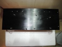
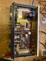
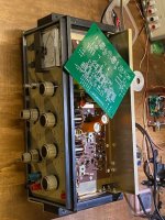
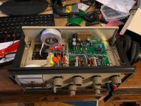
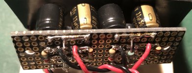
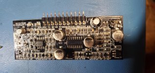
Now it happens that these day I need again tread some aluminium heatsink to hold 8 - T0264 Transistors, and also a large PCB with the size of 300x140 mm with a lot of component soldered to it.. So there are 8 Transistors that means 8 holes 8 times threading, and then also the stands for to hold the PCB fitted to the heat sink another 8. this makes 16 holes have to be drilled and 16 holes have to be threaded.

Take for one on hole a minimum time of 2.5 minutes to drill and to thread,
* any mechanic knows that this will not be enough time. * so then we have
16 x 2.5 minutes = 40 minutes, now we have two sides, left and rigth, so time doubles.. Again that would be fast, but I think 5 minutes for ome hole is average, so two pieces would take up 2.6 hours or 160 minutes. A lot of time..

This can be done faster. Go to a mechanical shop and have them done that.
You will need to draw them a layout, where the holes have to be. then may you have to wait because the shop has other customers which were first. And finally you have to pay them.

Do it by youself, get a Threading machine, for several hundred or even more Dollars. Or take this example and I can assure you that you will make one hole drilling and also threading under 2 minutes, neat and clean and of high quality.

There of course you will need a drilling machine, hand or standalone, and if possible brand new drills. HSS or better, make sure that the drill Cut Angle on top of the drill is correct for the material you are going to drill. that way you will get best results..

Till now no problem, anyone can drill a hole, but now threading, this is a thing for itself..
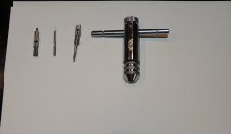
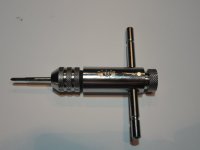
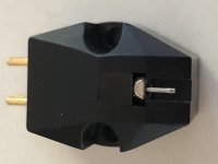
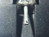
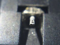
As threading will need forward and backward turning and also threading must be done on not to high speed most will use the manual way. Having a tool like to see in the picture..

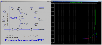
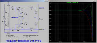
But now there is the option ot have a threading machine made DIY, which works perfect on aluminum thin Stainless Steel plates and also copper.
I made a VIDEO, just to show that this is real inexpensive and fast and can be done almost by everyone who has a hand for DIY..
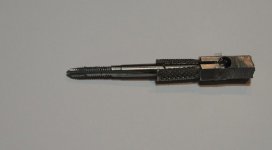
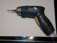
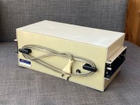
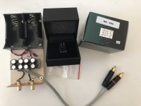
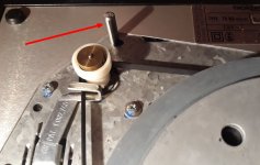
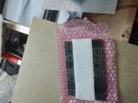
The Tool I use is this small hand drill, battery driven, to drill or to fix screws or bolts; I just modified and Steel bolt removed from MAC PRO to hold the Threadingdrill. Insert into the Hand drill and there we go.!

The rest you will understand if you look at the picture. Of course you will need some Cutting solution to drill holes or threading, but also this is inexpensive.. Lenox is the Brand Name I use, not to advertise this here, but it's rather cheap and good quality. This Heat sink time to drill and threading was less than 20 minutes. The thread are good to screw in aans out bolt at least a 100 times without losing the grip of the Bolt. So migth the one or other can make use of this.
Regards

Chris Hess

Attachments

  • 1. Threading tools.jpg
    1. Threading tools.jpg
    246.2 KB · Views: 349
  • 2. Treaddrill modified_s.jpg
    2. Treaddrill modified_s.jpg
    35.9 KB · Views: 363
  • 3. Manual Treading Tool.jpg
    3. Manual Treading Tool.jpg
    74.6 KB · Views: 344
  • 4. Workzone Threading Drill Mashine.jpg
    4. Workzone Threading Drill Mashine.jpg
    101.5 KB · Views: 342
  • 5.finsih drilled and threaded Heat Sink.jpg
    5.finsih drilled and threaded Heat Sink.jpg
    907.8 KB · Views: 320

Looking for any help finding a specific type of bluetooth receiver -

Hi, all:

I'm fiddling around with adding bluetooth to a 1990s GM Delco head unit - what I'm trying to find is a bluetooth module that allows audio to pass through while not activated but when activated, replaces the audio that would otherwise pass through. That way, if I can insert the module in the wiring from the cassette deck or am/fm to the amplifier, the sound would flow normally when the module was off but would be replaced by the bluetooth signal when the module is on. Basically, the same arrangement this jack has (Radio Shack 2740246).

My problem is that I don't know what a switch that'll do that is called, so I can't tell if items on Ebay / Amazon, etc. would fit the bill or not.

Any help greatly appreciated. 🙂

John

Custom tube torroid order calculation check please

Just looking for a critique/common sense check for the custom toroidal order I want to submit later this week. Sorry for the amount of info but it's complex hence asking for help.

Future requirement - to be able to use this transformer to test prototype modules for a later amp using tube based opamps etc. However for now this is V1:

V1 Amp requirements - this is the amp's requirements.

+320V at the B+ rail, 120mA total (per ch: 20mA max for cascode, 2x20mA for drivers)
-320V at the B- rail, 40mA total (per ch: 20mA for cascode only, drivers are to ground)
+200V at the output B+ rail, 480mA (per ch: 4x60mA)
-200V at the output B- rail, 480mA (per ch: 4z60mA)

Each supply will ultimately have a 9H choke then a maida regulator. I will find out the choke resistance but for now I'm using spec for a 9H toroidy choke (29ohm) and then putting ~30V drop for the maida. The supply is full wave rectified hence 1.414 voltage increase and I'm making an assumption of 0.60 current drop.

Thus the power supply requirement for the 320V rails at 160mA:
320 + 30 + (0.16*29) = 355V, then /1.414 = 251V voltage from the secondary.
160mA / 0.60 = 266mA required from the secondary.

Thus ~ 215*0.266 = ~ 60VA minimum

For the power supply for the 200V rails at 480mA:
200 + 30 + (0.48*29) = 244V, then /1.414 = 172V voltage from the secondary
480mA / 0.60 = 800mA required from the secondary.

Thus 172*0.8 = ~140VA minimum


Heater requirements

12.6V Heater referenced to +50V, 3.4A total from the following:
* 2x 3x300mA
* 2x 2x400mA

12.6V Heater referenced to -150V, 2.4A total from the following:
* 2x 1x300mA
* 2x 2x400mA

This will be regulated DC, again this will likely be a RC (5ohm) with a maida (10V drop configured), full wave rectified. Just taking the larger current at 3.4A:
12.6V + 10V + 3.4*5 = 40V, then /1.414 = 28.2V or 30V
3.4A / 0.60 = 5.7A

30 * 5.7 = 171VA

So anything I may have forgotten (perhaps 2-3V for the diode drop?) or observations?

I'd like to finalise the order later this week.

FS: Heathkit IG-18, EU good condition

I want to sell a Heathkit IG-18 i got for a project that I do not have time to even start.
It is good overall condition, perfectly working and as far as I can tell, in spec. Inside, everything is original, very clean and all switches are in great condition - again as far as I can tell. This is no collector's item, it is a working device with a bit of scruffs and repainted covers (not by me); only missing the black plastic side handles - see pictures (which were purely aesthetic IMHO...) and two banana post thumbcovers, otherwise absolutely complete.
The electronics inside are all OK, when I got it I checked the electrolithics and they were OK, I just replaced a small one that was going south.
Front plate is very nice, and it still has the original power cord - whoever gets this, replace the cord!
Wired originally for 220/240V.
I am also including a PCB to build the IG-18SL, a complete rebuild of the Heathkit oscillator using the HP339 schematic, pioneered by Steve Lafferty. I am also including a pic of a built board inside another IG-18. Details of the build are available on Tronola.com.

Asking 70 Euro plus shipping.

SOLD, thank you everyone. It's in a tube amp builder's home now!

Attachments

  • heath-9.jpg
    heath-9.jpg
    102.8 KB · Views: 143
  • heath-10.jpg
    heath-10.jpg
    92.3 KB · Views: 144
  • heath-12.jpg
    heath-12.jpg
    96.4 KB · Views: 142
  • heath-13.jpg
    heath-13.jpg
    97.9 KB · Views: 148
  • heath-1.jpg
    heath-1.jpg
    110.9 KB · Views: 140
  • heath-2.jpg
    heath-2.jpg
    115.3 KB · Views: 81
  • heath-3.jpg
    heath-3.jpg
    88.1 KB · Views: 77
  • heath-7.jpg
    heath-7.jpg
    117.5 KB · Views: 82
  • heath-8.jpg
    heath-8.jpg
    99.7 KB · Views: 80
  • heath-11.jpg
    heath-11.jpg
    93.5 KB · Views: 89

Cost-no-object headamp / preamp

Hello to one and all,

I am a new member and a total noob with minimal soldering skills who would like to build a headamp / preamp, preferably with 2*6SN7, 2*300B, 1 or 2*274B, as well as XLR input / output.

Is it gonna be very difficult?

What is the complete list of components out there that I need to buy? (finest quality possible)

Also any schematics available?

Cheers everyone!

Amplifier repair

Hello all,

I recently picked up a blown MTX 2300x strictly for a learning project as I have taken a recent interest in amplifier design. I am still quite new to this, so please bear with me...

The original owner was hooking up a capacitor when the amp blew.

I hooked up the amp on my bench with no input, and no speakers hooked up and read 44VDC across the left channel. It would read 44VDC for 2-3 seconds, drop to 0V for about 1 second, then continue repeating the cycle.

I took the amp apart and found one shorted fet on the left channel.

I removed the 4 fets in that group (center row, top) and tested the amp again (is this a bad idea?)

Now with the fets removed on the left channel I powered up the amp to see if there was any output on the right channel. It was very weak and severly distorted, could this be due to the fact the fets on the left channel are removed?

Also, the fan does not start for some reason, before I removed the fets the fan worked, but was super noisy. I am not sure if it is activatedy by a rise in temp. or not.

I am going to remove the rest of the fets tonight and test for shorts.

Are there any other tests I can perform on the amp before I solder in some new parts? I dont want to replace them all again. Anything else I can test while I have it apart?

Thanks for any help.
An externally hosted image should be here but it was not working when we last tested it.

FS: Hana SL with active MC preamp

USD450 Hana SL with MC headamp compatible with phono MM input.

The cart was purchased May 2020, played couple of hours every week and put on storage after a year.
Sl with shibata stylus should last 2000 hours
Review: The Shibata Syndrome – Hana SL, a killer sub-$1,000 cartridge | Part-Time Audiophile

MC headamp is based on Richard Lee's MC-pre circuit, with ZTX851/951 pair, Panasonic FM, Nichicon KZ MUSE capacitors and Takman REY resistors, much quieter than SUT.
Two D cells last for whole year in always on state.
https://www.lencoheaven.net/forum/index.php?topic=35960.0
Richard Lee’s Ultra-Low Noise MC Head Amp

Attachments

  • sl-1a.jpg
    sl-1a.jpg
    562.1 KB · Views: 197
  • sl-3.jpg
    sl-3.jpg
    357 KB · Views: 188
  • sl-5.jpg
    sl-5.jpg
    482.7 KB · Views: 183
  • sl-4.jpg
    sl-4.jpg
    538.4 KB · Views: 188
  • sl-7b.jpg
    sl-7b.jpg
    764.9 KB · Views: 193
  • sl-9b.jpg
    sl-9b.jpg
    159.6 KB · Views: 115

Heathkit Guitar amp tremolo capacitors

Hello,

I have a Heathkit guitar amp with a tremolo working intermittently. The optocoupler is working as of now, and Ive replaced all the electrolytic capacitors. I am not getting the voltages, indicated on the schematics, to the transistors, so I took out the 3 0.22uf capacitors to check them. 2 of them broke when I did, so I am going to replace them.

The ones in there are 250V. Would a 100V replacement be ok? Or 0.1uf? These are options I have on hand.

Thanks
http://ctgelectronics.weebly.com/uploads/3/1/6/6/3166248/6483742_orig.png

A strange (for me) Turnberry story, any idea ?

Dear friends,

First of all I apologize in advance for any possible forum rules violations of mine. This is my first post!

This is a strange story (maybe not so strange for people more expert than me) I would like to get Your comments about.

During the ‘strong’ phase of the pandemy one of my old AR91’s died and wanting to give myself a present in that sad situation, given the plenty of good reviews on the net, I took the risk of buying a pair of used Turnberry SEs without listening to them before.

They arrived like-new in their original packages, not even waxed, no sign of use/intrusion!

I connected to my amp and listened … terrible! A dull, boomy, muddy sound I could only slightly improve with the help of a good 5 bands parametric EQ.

I am old but my doctor says I just have a slight loss from 5 Khz. Other younger people listened to the speakers and had the same sensation. I tried different positions, rooms, amplifiers (SS, PP Tube, Class A ss) ….. no improvement!

After 2 months of readings and tests I disconnected the tweeter’s plug and paralleled the medium bass with a couple of ‘poor’ (but stylish) Grundig ‘satellites’ from the 70’s I had just restored. They have a nominal 400 to 20.000 Hz range.

The sound immediately opened, even with the limits of such drivers.

Next I connected the Tannoy’s high freq. driver with a handwired copy of the original Tannoy filter (a simple RC cell) and fed it with a 1 Khz, 1 Vpp sine signal from my generator.

I got only a very very feeble output. Same behaviour for both drivers (left and right). I also checked the Tannoy filter cap (2.2 uF film), capacity is ok, ESR near 0.

In desperation (Tannoy driver burnt?) I started paralleling the Tannoy RC cell cap with some bipolars I have, increasing the resulting value. As far as I know this should lower the cut frequency of the cell.
With 6.6 uF total capacity vs. the original 2.2 uF I mounted back the drivers in their cases.

…… The sound is, let’s say, 10 times better than before, voice is clear, highs are brilliant. Even if the general impressioni is obviously of some unbalance, I perceive the general quality of this loudspeaker. I am now starting to test different cap values to find the best compromise. My Eq will could the rest I hope.

Some of You can explain ? Burnt drivers should give, I think, more serious symptoms than low output level. The 2.2 RC cell cap seems to be the standard for Tannoy Turnberries. Both loudspeakers behave the same way. Maybe this was an experimental series of Tannoy drivers ? a market-specific configuration? what can be reasons for such a defective (for me but not only for me) behaviour ?

Thanks for Your kind suggestions and opinions

Manlio

Circular Flare in Plywood.

Having had the recent fortune to obtain a good pile of 3/4 furniture grade plywood, I began construction of MJK's 18" H frames and the two 20" square OB baffle boards that sit on top.

I'm not a very good furniture maker and can eek out a "C" grade cob-struction at best. I shoot myself in the foot at least a few times during any such project, which adds hours onto the task to correct.

This time I cut the rear chamfer flare for my 4" MarkAudio Pluvia 7 HD speakers on the wrong side of the baffle board. Cut it on both before realizing. As I was so lucky that the pile yielded enough for two H frames plus two 20 X 20" baffles, I cant just flip them and use the backside...

It's salvageable. However it occurred to me that I could turn the mis-sided flare into a short circular waveguide - I've seen them where folks mount a driver front flange against the back of the baffle, letting the driver project through the baffle and flare. This would leave the back of the driver wide open for OB purposes.

I have no idea how to do this on a 4" round hole, offset in a 20" square board. Except file and sandpaper away, until it looks about right. The only tool I have which might help is a Craftsman table router, where I suppose I could remove the fence, get a bead bit with the bearing on the end and chase the somewhat square edge of the somewhat circlular cutout. Sounds like a disaster...

Maybe I'm better off just mounting the speaker however I can; there's enough material for the screws to sink into if I dont flare the back side too wildly - or at all.

1. Would a circular flare of unknown "looks about right" shape ruin the sound of the Pluvia HD, when mounted to the back of the baffle?

2. Should I bother to flare the backside, risk losing the two pieces for mounting the PHDs? I can still cut 8" holes and run a set of Visaton BG 20s I have.

3. I have enough wood stock that I could enlarge the holes to, say, 6" and put the drivers on a suprabaffle. My mistake doubles the effort...

Thanks for any insight you'd care to share.

Guitar amp using only 6F12P (6Ф12П) valves - can it be done?

Hi everyone,

I built an AC15-style amp last year. It was my first attempt at making something with valves in it and it sounds pretty good. I have an idea for a second build, but my knowledge of some of the theory behind this stuff is still patchy at best 😀 So with that in mind, I throw this idea out there to the forum in the hope that someone might very kindly sense-check it before I start buying parts etc..

Is it possible to build a low-wattage guitar amp using only 3x 6F12P (6Ф12П) valves?

The 6F12P is a split triode/pentode valve in a single envelope, with the pentode section having a max dissipation of 5 watts @ 330ma heater current.

I'm thinking you could use 2 of the pentode sections as a push-pull output stage, with the 2 triode sections joined together to form the phase inverter (LTP). If that works, you get a PI and output stage for only 660ma heater current. I'm guessing here... but I'd hope you could get something like 7 watts output from it (cathode biased)?

The third 6F12P would be the input stage. You could use the pentode section as the first gain stage, a bit like the old EF86-based Vox circuits. The remaining triode could drive a tone-stack or maybe act as a gain boost.

Worth trying? Or doomed to failure?

Vintage 3Watt Tube

Hello Solder slingers

I have a 3 Watt single-ended power amplifier made by Packard/Bell. It was scavenged from a small console stereo. I no longer have the preamp section or the speakers. But as a stand-alone amp using EL84 tubes it can power a full range pair of speakers. I'd like to turn this into a HeadPhone amp with volume control and a single input! I know very little about amplifiers, but I thought some guidance could be found here in Tubes and Valves. I do have a schematic someplace from a long-ago curiosity search. Help, suggestions, directions?

Thanks, kingfisher

Sherwood AD-2220 CP Please Help!!

Hi guys i have some real troubling problems with my sherwood amp, other than its 100 years old and cant afford a schematic .. i realy need 2 photos / resistor codes if someone could help me out that would be soo greatly appreciated.

i need a good quality photo of the protection board ( it has a 5112100 stamp on it its small & square, fits in your palm the other is onthe left side of the power supply (right near the relay) there is a couple of little green resistors i need to see the codes for they, same with the protect board i'll note their names

i would love to hear this amplifier, the only way that will happen is if i can repair it, i have no problem fixing things but the resistors are completely fried and i cant read their bands! please help!!

the codes are (POWER/AMP BOARD) R401R & R401L (Their located near the 2 10 ohm 2 watt resistors (grey colour risen off the board)

and R329R & R329L (PROTECT BOARD)

I have replaced the 2 left and right R330 resistors with 1 watt resistors, even if someone has a service manual i would realy love if i could have some help please please helpp!!

Options for bass in dipole system

I'm looking into adding two subs, maybe sealed or H-frame OB, and maybe run the H OB further into bass, and wanted to gain insight from the experienced.

My system: two 12" Rythmik servo subs in DIY sealed boxes below 65Hz in mono, and per side: one 18" Faital 18HP1010 baffleless dipole on a swing from 65 to 275Hz, twin 8" from 275Hz to 1.8kHz (bottom 8" on U baffle to reach to 275Hz) and AMT above. Active 4-way, digital xo and room correction.

Happy with Rythmik sealed subs and thought about adding two more to get a distributed bass array. And I came across GR Research/Rythmik OB servo subs in H or W baffle, getting great comments, that can be xo up to 200 or 250Hz. Looking at their model with dual 12" per sub.

And this has me thinking about these options:
  1. add two sealed Rythmiks to the existing two and play 20-65Hz.
  2. add two GR Research H baffles to the two sealed and play all of them 20-65Hz. I wonder if mixing sealed with dipole bass, despite both being servo-driven, would be detrimental.
  3. add two GR Research H baffles and play them 20-200Hz with the two sealed reinforcing 20-65Hz. Getting DBA below 65Hz. 2x12" have less surface than a 18", probably noticeable from 65 to 100Hz or so, but the GR have servo so allegedly more controlled/articulated than the 18".
  4. add two sealed Rythmiks to the existing two and play 20-65Hz, and later add two GR Research doing 65-200Hz with a shallower H or just a panel. This might in turn drive me to replace the 18" with a 12" dipole which eventually would allow to raise the xo to the mids from 275Hz to 400Hz or so.

The room: it's the living room, with little flexibility as to placement. It's 30x16x2.4 feet high, divided into two sections (dining and living room) by a wide sliding door. Current subs and speakers shown in blue, and the listening seat.
room.jpg

The grey squares show where the two new sealed subs would go, or where the sealed subs would go should I get OB subs. OB subs could be placed somewhat away from the corners, but baffle would likely be about 30" from front wall.

What are your thoughts about OB vs sealed bass below 65Hz?
And baffleless 18" vs twin servo 12" on a baffle in 65 to 200Hz region?

Thanks in advance!

speakerparts.co - CNC flatpacks / custom + public designs

Anyone interested in a build but put off by lack of CNC or wood skills, we provide CNC flatpacks for any simple or medium complexity builds.

The website is in works (Custom CNC cut DIY speaker cabinet flatpacks baffles MDF Baltic Birch – SpeakerParts) but you can message me for ordering. Welcoming trial users. 🙂 We are in the KC area so shipping should be reasonable all over the US.

Transistor Ft as function of Vce?

To build the perfect amplifier that we all want - we need to know how transistor Ft varies with Vce. So we can optimise.

Bob Cordell's book (p22) says Ft droop at lower Vce at hi current, with a "Vce ... as little as 5V ... current ... several amperes" in an example.
The On semiconductor datasheet for the MJL4281A (fig.9) has the reverse, with better Ft at Vce=5 than Vce=10 for the entire current range shown (.1A to 10A)
A net search didn't show much accessible research. I even overworked my brain with the original Gummel_Poon paper in the Bell Systems Journal.😱 I suspect there's several different effects that interact in a complicated way. Any pointers to more information or an explanation?
Or it could just be a mistake in the datasheet.
Edit: Which is what it is.

help with jl audio e1200

When connecting the amplifier it does not turn on and consumes more than 7 amperes without load, disconnect the loads one by one and detect a possible short, all the power section transitors were disconnected, and the equipment turns on, a mosfet transistor was discovered in short j111, The detail is that when you reconnect the power transsitors and stop turning on the equipment, when making some voltage measurements it is detected that in the gate terminal of the section that is fed from the positive +35 v of the mosfet there are 15 volts, some suggestion.

Attachments

  • WhatsApp Image 2021-08-02 at 9.18.31 PM (1).jpeg
    WhatsApp Image 2021-08-02 at 9.18.31 PM (1).jpeg
    63.2 KB · Views: 78
  • WhatsApp Image 2021-08-02 at 9.18.31 PM (3).jpeg
    WhatsApp Image 2021-08-02 at 9.18.31 PM (3).jpeg
    85.8 KB · Views: 86
  • WhatsApp Image 2021-08-02 at 9.18.31 PM (2).jpeg
    WhatsApp Image 2021-08-02 at 9.18.31 PM (2).jpeg
    116 KB · Views: 74

TPA3122D2N Solderless Breadboard

So I'm working on a project that's fairly complex overall with many components and one component is a power amplifier stage after a PCM5102 DAC. I'm basically retrofitting an old radio with entirely new "guts". I'll write more about it later, it's quite an adventure, but one component is a power amp stage. I've not built an amp before but I was aiming for Class-D mainly because they run cool and so don't need a heatsink.

For this project, I'm trying to go all-through hole. The radio isn't huge so I don't need to worry about getting loads of power from the amplifier. I found the TPA3122D2N, but I'm worried it's actually not powerful enough, so I wanted to breadboard it to test it with the speakers in the radio before I build (and pay for) a complex PCB. I'm leveraging the existing transformer which provides around 13.5V DC once rectified and smoothed.

I bought all the components needed (basically the list from the TPA3122D2N datasheet) and started building. But I can't generally get the thing to make any sound. This is probably because it's on a solderless breadboard. I did get it to make sound once(!) but then I turned it off and when I powered it up again, nothing. All I get is a rhythmic clicking at about 4Hz.

My schematic is attached, although I've since switched from BTL to SE (by providing L/R on the inputs and splitting the outputs accordingly) since my input signal will be SE from the DAC.

This is tearing my hair out! Can anyone make some suggestions, or should I give up with the solderless breadboard?

Attachments

  • Schematic_Bose Upferb_2021-05-15.png
    Schematic_Bose Upferb_2021-05-15.png
    29.7 KB · Views: 469

Akai AM2450 Volume in one channel fades

recently picked up an Akai AM2450 and has issue of audio in either channel fading out and sounds distorted while it does. When this happens its only to one channel and can be either.

turning up the volume temporarily fixes it.

I thought it'd simply be dirty volume pot and or dirty contacts in the speaker relay. However the issue persists.

oh and wow what a relay! the thing should have a clear casing to show off it's internals lol

The caps look original, unless they were replaced long ago and in entirety.

The volume pot had a ton of oil residue, it has a particularly open design. but I don't think the issue is either of those components. its been cleaned.

Particularly because the issue can be one channel or the other.

all other adjustments sound and work fine; balance, bass, treble. switches sound fine too; input, Loudness, Mono / Stereo, A/B speaker.

It has watt meters, which work when speaker switch is off...however when the fade out issue happens
it can be seen in the watt meter...it slowly decreases in magnitude.

The pots for bias look rather suspect / are completely open design.

Any ideas?

SSE sounding muddy. Could I have something connected wrong?

Hi all. I built an SSE awhile back, and I'm finally getting some free time to listen to it on the regular. Right away, I've found that it doesn't sound very good. Muddy. Almost muffled sound. I've tried other amps with the same speakers and they sound clear as a bell, so I suspect maybe something is up with my SSE.

Mine is built in the standard configuration. It has motor cap and choke. Tubes are EL34, and the output transformers are Toroidy TTG-EL34SE.

To those who might be willing to help me figure this out: What information do you need from me? Would photographs help? Any other part numbers you need? I'd love to get this sorted, as I think this amp has lots of potential. So I'm happy to provide any additional info.

Thanks in advance, Tubelab gang!

The Output stage querries !!!

Gentlemen,

Iam looking to build an amplifier for myself with IPs(considering spooky, ComSuMo, Wolverine, GLA surviour) & OPs on different board so that I can interchange the IPs only incase required.

Iam looking for 2 options:

1. Lateral Mosfet stage OPS

2. BJT OPs stage

As a DIY starter want suggestion on OPs:
a. If I consider Slewmaster OPs with drivers changes to Lateral mosfets(not sure if anyone has tried this way) what could be effected in terms of sonics ?
b. Has anyone tried https://www.synaesthesia.ca/OP-stage.html ?? Or any better suggestion with L-Mosfet OPs is requested.

Thank in Advance,
Suman

Idss tests of LSK489 and LSJ689

A few months ago I ordered a few JFets from an internet site that had limited supply. I only ordered (4) LSK489 and (4) LSJ689. Results for Idss of the LSJ689 had a wider range than I expected (and the high Idss get noticably warm). There is no way to order grades like other parts such as LSK170, LSJ74, LSK389.
So if you need 2 pairs, I guess the safest thing to do is order 4 😕. I'm not sure changing ccs or source degeneration resistors is a better way to make up for good matching..
There's another supplier of Linear Systems that has many more parts in stock. Maybe better luck with them? Could others post results if you have them available?

LSK489: 3.41mA (A), 5.46mA (B), 6.04mA (B), 7.80mA (B)
LSJ689: 6.47mA (A), 7.10mA (B), 11.76mA (B-C), 14.56mA(C)

Attached picture of test setup, Vgs=0V, Vds=10V, measured using ammeter V+ to Vd for Ntype and Vd to V- for Ptype.
Also attached spice sim for all grades as reference.

Attachments

Which of these ICs can be swapped out with the OPA2134?

There is/was a shop in Idaho that was doing upgrades to the DBX 3BX series one dynamic range expander. One of the things they did was swap out ICs for a much better OPA2134. It was a drop in replacement, no mods to the surrounding circuit needed. Other than that I can’t get any other information. This is what is in the unit:

10 - LF351N
8 - LF353N
10 - RC4558P
1 - LM301N
3 - unknown, the markings have been removed.

My best guess is the RC4558P. Could it be possible to replace the LF351N and LF353N with the OPA134 and OPA2134? I really wish I could get more info on this.

Is link a schematic, but the only one I can find isnt the best quality and needs to be zoomed in on. The images I post get fairly degraded.


Thank you,
Dan

Pioneer BOFU 4 sale

found a pair of the Pioneer BOFU drivers in the office today. thought they were gone.

anyway, is anyone interested in buying these? the surrounds are good. they were installed in a pair of the hedlund cabinets & then returned to the original shipping box from parts-express.

$50 + shipping. probably via fedex or ups.

if any are interested, i'll post some pics.

thanks.

Mutual coupling question

I found this in some ElectroVoice product literature:

"When two speaker systems are placed side by side, the woofer cones “mutually couple,” causing the two systems to act as one system with twice the effective cone area at very-low frequencies, giving an additional 3-dB increase in maximum acoustic output. Mutual coupling will occur when the frequency is such that the center-to-center distance between the two woofer manifolds is less than about one-half wavelength."

I have two identical subwoofer cabinets, placed side by side in a corner of my listening room. They are crossed over actively at 90 Hz. I've been trying to get my head around the mutual coupling thing as it applies to these boxes. Here are the numbers:

Center-to-center distance = 44.7675 cm

Estimated Speed of Sound = 34500 cm per second

Frequency = Speed of Sound / Wavelength

For Wavelength = 89.535 cm, Frequency = 34500 / 89.535 = 385.3 Hz

What I get from this is that mutual coupling only occurs above 385.3 Hz. I wouldn't call these "very-low frequencies"! What am I missing here?

EDIT: I did a search here and now I'm even more confised....

I found this formula:

Fo = c/(d*sqrt👎)

Where

"c" is the speed of sound in the air in metres per second (normally 343 is used, but can vary slightly according to air temperature and humidity).

"d" is the distance in metres between the two speakers

"n" is the number of sources.

Fo = 343 / ( .447675 * 1.4142 ) = 541.77 Hz

Help?

Thanks,

dooper

Help please - Sub sounds *blah*

I've have a Stryke Audio HE-15 in a 22" cube with two 18" PR's. My box (purchased pre-made) is roughly half of the box pictured (actual interior dimensions are around 22"x22"x22") in the following link - thanks "greg", it's hard to find these specs nowadays.

link for subwoofer

I have a Mackie m2600 to power it (I bought this used). Here is a link for the specs:

link for mackie

I have the Stryke's 3ohm dual voice coils wired in a series.

My problem with this is the output.

With the mackie in bridged mono mode, I do not think I am getting adequate output. The amp shows that it is giving it all she's got (the front led's light up to the "clip" level), but the sub is barely moving...maybe 3/4 inch excursion. And the sound level is certainly lower the my SA 12 in a 1ft^3 sealed box with a 500w digital amplifier.

The mackie has the low pass filters off and the crossover at 120hz.

What's going on here? I have access to a much smaller amp (around 150w) and I only have rudimentary tools (a Radioshack db meter and multi-meter).

Am I expecting to much?

If not, what steps should I take to test the driver, passive radiators, box design, and amplifier? - I'm gonna assume that the box design is OK at least.

Any help would be much appreciated!

Thank you,
Chris

Anyone done a custom PCB for a small low fi BT/AMP before?

i've been watching a few youtube videos (like probably most of you), which were actually non audio related and noticed how many people seem to be getting PCB's and custom chips made, which made me think of has anyone done a small bt amp for a lowfi build?

i've bought a few CSR8645 Amplifier Boards and other variants of them (QCC3008) and due to the size find it difficult to firstly solder onto, but trying to cram it, plus a battery and a boost coverter all into a tiny build.

So my question would be, has anyone done a custom build, if yes, would it be hard to do for somebody who doesnt know how (but keen to learn) and how hard would it be to integrate something like a TP4056/7 1S BMS and a boost coverter (3.7 to 5v) etc?

I have a few builds which are basically 3d printed 500ml beer cans with a downward firing 2inch full range and i want to use the amp as it has the ability to be modified through the BT chip and use custom EQ settings (and it is small).

example

Csr8635 dual 5w bluetooth 4.0 /4.1 amplifier board audio bluetooth 4.1 receiver module with call function Sale - Banggood.com

Info on mercury rectifier DCG1000-01

I have some mercury rectifiers that I have not planned on using. But I am tinkering with the idea of a 'show off' amp just for demonstrating the fascinating side of tubes, and tube glow is a part of that.

One set I thought of using is a pair of Philips DCG/1000-01. But I cannot find any data on filament voltage and current.

I do find the DCG4/1000, this has 2.5V/4.8A filaments. So can I assume DCG/1000-01 is 2.5V but only 1A?

Any one here know?

As for using mercury rectifiers. I know some of the risks, probably not all, I know one must apply heater power long before HT (at least 1 minute?). Is there a tell tale way of knowing when one of these are bad, and even if they may catastrophically self destruct?

If I want to dispose of them, where do I drop them off? I guess the local dump has 'dangerous goods' section and will send them to where they belong. I dont intend on selling them, just because I dont like poison going to who knows where...
Or am I over reacting?

thnx for comments

Siemens F2A tubes

4 pieces of F2A tubes for sale $400usd OBO , one of the pair is used for a few tens of hours for an experiment. The other pair is plugged in for tests, and then stored. Selling as it is, no returns. Pm me to check shipping cost to your location. Will ship from Singapore.

Attachments

  • IMG_20210802_095622_resized_20210802_100340341.jpg
    IMG_20210802_095622_resized_20210802_100340341.jpg
    612.3 KB · Views: 229
  • IMG_20210802_095628_resized_20210802_100337694.jpg
    IMG_20210802_095628_resized_20210802_100337694.jpg
    428.2 KB · Views: 230
  • IMG_20210802_095643_resized_20210802_100338546.jpg
    IMG_20210802_095643_resized_20210802_100338546.jpg
    644.3 KB · Views: 228
  • IMG_20210802_095814_resized_20210802_100338856.jpg
    IMG_20210802_095814_resized_20210802_100338856.jpg
    495.6 KB · Views: 221
  • IMG_20210802_095835_resized_20210802_100339480.jpg
    IMG_20210802_095835_resized_20210802_100339480.jpg
    420.1 KB · Views: 217
  • IMG_20210802_095841_resized_20210802_100339825.jpg
    IMG_20210802_095841_resized_20210802_100339825.jpg
    508.9 KB · Views: 93
  • IMG_20210802_095852_resized_20210802_100340087.jpg
    IMG_20210802_095852_resized_20210802_100340087.jpg
    478.9 KB · Views: 116

WAV playing - Advices for beginner

Bit-Perfect playing WAVs - Advices for beginner

I'm just taking the first steps to get good stereo music from my WAVs through an entry-level system made up of a digital interface, a (digital) stereo amp and a pair of passive speakers running Windows 7 x64: no audio NAS, no media streaming, no music server intended.

I'm passionate and experienced about listening to music, both live and played within the walls of a room, but through my PC I have almost no experience at all and even if my PC-based system is currently an entry-level one I would like to (understand and to) get the max possible quality sound from, so I started reading and still reading articles and discussions, but now I'm a bit confused and would like to receive authoritative confirmations or even denials about some basic principles.

Running a capable software player is the Bit-Perfect playback applicable to WAV files?
If so, how do you get it?

I'm just trying 2 players that I like: Album Player (free) which I really like and JRiver Media Center (commercial) which I like enough, both with strengths and weaknesses and both with the ability to use the ASIO driver supplied with my audio interface.

I think I understand that if you use ASIO driver (or WASAPI too) for the Bit-Perfect playback then both Windows mixer and volume control are just bypassed and no longer functional, but I still can't get it: is the above true also playing WAV files?

Definitely, how to get theoretically and practically the best possible sound quality from my system playing WAV files under Windows 7?

Many thanks in advance for any appreciated addressing.

ONIX Power Amplifier Model OA701 (OA-701) Schematic wanted

This amp works fine, but there is a hot spot on the amplifier PCB. The reason are two very hot transistors from front-end in a E-line envelope like this outline:
https://www.diodes.com/assets/Datasheets/ZTX652.pdf

For check the reason in detail I want to have a service manual or at least the schematic diagram.

Under
History | ONIX - Hi-End audio products from england since 1979
there isn't to find a download portal for pdf schematics and service manuals.

Who can upload the schematic?

More URLs:
https://www.audiovintage.fr/leforum/viewtopic.php?t=37135 (images)
Onix Audio - Wikipedia

Emilar ew15-8a (altec style woofer) .?

Hey

Plan to build a old school large 2-way, perhaps petite Onken, or altec 612, or similar. Found a pair of Fostex H320 wooden horns (tips for a 1” cd going low would be nice, or if building an adapter to 1.4” is more clever, would probably work).

There are some old Emilar ew15-8a 15” woofers available, together with Emilar Ec175 and upgraded Emilar crossover of 800hz.

From some old threads, it sounds like the Emilar elements are compared favourably to Altec etc., but do any of you know? Or even have data for especially the woofers? (I read fs of 21 hz, likes large cabinets, was in a 220l box).
Maybe worth a gamble? Or better keep looking for a 414 / 416 / ? (Really hard in Sweden..)

Thanks in advance 😬

What would you do if you lived forever?

What would you do if you lived 3000+ years?

Read an interesting article: assume all medical issues are solvable and nobody dies of illness or old age problems. You keep the mind and body of, say, a 30yr old, indefinitely.
How long would you live then? The surprising answer came from life insurance actuarials: about 3000 years. That is the average life expectancy in our part of the world, based on only accidents, suicide, murders, that sort of thing.

Then I though: what would I do with so much time? Build your own home, a brick a day? Spend 30 years to learn all about amp design, design the ultimate one and build it including designing and building each part? Take up a study and spend 50 years to learn all there is to learn about, say, the Roman empire including doing an in-place decade of archeological digging?
Would you jump off the roof top due to sheer boredom after a couple of centuries?

The sky would be the limit!

Jan

Halfler P230

I have a Halfler P230 amp. Even at very low volume, my speakers sound like they have bass breakup. I tried other speakers, and they do the same thing.
I checked the large power caps (10000uf 75 volts) with a VTOM. Infinite resistance. If indeed the caps are bad, would that cause this problem??? How doe the amp even work if these caps are bad?

Kairos Three-ways

I’m considering doing a build of Jeff Bagby’s Kairos 3-ways. I have built the CJD Khanspires, a Dayton RS series 3-way, and like them. I’m now interested in building something with a bit higher end drivers and a bit more exotic cabinet construction would be fun too. These will go in a 12x12 home office, so I don’t need huge output, but…

Has anyone built these, and if so what are your thoughts? Would you recommend an alternative for full-range, high quality sound smallish room?

Test results: wow/flutter & heavier mass platter

I recently purchased a mint condition 1961 Empire 208 turntable. Everything was in excellent condition, sans the belt and rubber mounts. I replaced the belt and rubber mounts. I also re-lubed the motor thrust plate, turned the thrust plate over to the fresh side and inserted a new precision ceramic ball in the motor thrust plate. The platter spindle has a steel ball bearing which needs to be replaced, but I have not done so yet.

Using the iphone RPM app to record speed and wow/flutter (I can not vouche for the accuracy of the RPM app, but its the best I have), I recorded several measurements for speed accuracy and wow/flutter. FYI: I use a Long Dog Audio LDA Quartz Regenerator power supply which keeps a steady voltage. The Long Dog Audio unit allows the platter speed to be adjusted easily with 0.01 increments. So, I was able to lock into 33.33 RPMs and it did not fluctuate during use.

Using the stock platter (aluminum which rings like a church bell), the iphone RPM app recorded a wow & flutter measurement of 0.16 - 0.18%. This range was consistent across 3 measurements.

Then, I added a 60 pound platter from a prior DIY project to the top of the stock platter. The 60 pound platter was centered within 0.001" TIR. With the added mass, the wow & flutter measured 0.06 - 0.08% (again measured 3 times). The only variable between the measurements was the platter weight.

Also of note, with the stock platter and motor off, I spun the platter and it continues to spin for a few minutes. I used a stethoscope to listen for bearing noise. None detectable. In all my years of using a stethoscope, I always detected bearing noise until today. Quite a nice feat for a stock 1961 turntable.

Then, with the 60 pound platter added to the stock platter, I once again spun the platters and used the stethoscope. Bearing noise was clearly audible. The bearing noise was cyclical which indicates that the sleeve bearing is where the noise is occurring, not the steel thrust plate. The sleeve bearing noise was likely caused by a slight imbalance in the platters weight distribution and thus would shift the bearing laterally and create the bearing noise.

So, where does this leave us:

1. 60 lbs incremental platter mass reduced wow/flutter by 50-66%.
2. Heavy platter needs to be appropriately balanced to no longer cause the sleeve bearing noise.

The 60 lbs platter is not suitable for the current setup (see photos), as it was taken from a 17" OD Gates CB500 transcription table. So, I am considering a new high mass platter and bearing.

Meanwhile, the stock papst motor purrs like a kitten, albeit with the fan noise that is inaudible at the listening position.

More to come.

Pat

Attachments

  • Screen Shot 2021-08-03 at 1.20.07 PM.jpg
    Screen Shot 2021-08-03 at 1.20.07 PM.jpg
    70.8 KB · Views: 277
  • Screen Shot 2021-08-03 at 1.20.18 PM.jpg
    Screen Shot 2021-08-03 at 1.20.18 PM.jpg
    193.9 KB · Views: 264
Projects by fanatics, for fanatics
Get answers and advice for everyone wanting to learn the art of audio.
Join the Community
507,663
Members
7,883,181
Messages

Filter

Forum Statistics

Threads
405,981
Messages
7,883,181
Members
507,663
Latest member
The driver